/ 6/10kV
Medium Voltage XLPE Insulated Power Cable YJLV
Model: YJLV / Aluminum MV Cable
Medium voltage XLPE insulated power cable designed for utility networks, substations, and industrial power systems.
- Voltage Rating
- 6/10kV
- Number of Cores
- Array
- Cross Section
- 25–1000 mm²
- Conductor
- Aluminum
- Armoring
- Steel Tape Armored
- MOQ
- ≥ 100 m
Standards & Certifications
- IEC
- IEC 60502
Downloads
Specifications
Technical Specifications & Performance
Construction
- Model / Series
- YJLV / Aluminum MV Cable
- Voltage Rating
- 6/10kV
- Conductor Material
- Aluminum
- Conductor Class
- Class 2 Stranded
- Cross Section
- 25–1000 mm²
- Number of Cores
- Array
- Insulation
- XLPE
- Sheath
- PVC
- Armoring
- Steel Tape Armored
- MOQ
- ≥ 100 m
Performance
- Max. Conductor Temp.
- 90°C
- Min. Bending Radius
- 15 × Cable Outer Diameter
About This Product
The Universal Cable for Medium-Voltage Distribution Networks
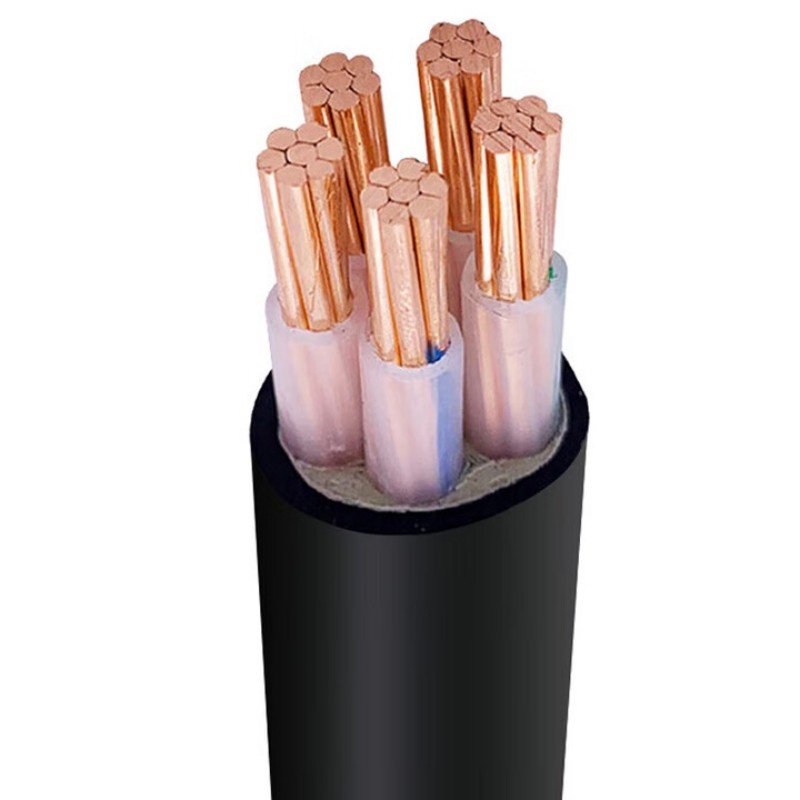
Medium Voltage XLPE Insulated Power Cable (universally known as YJLV for the aluminium-conductor variant, internationally equivalent to NA2XSY per the European VDE/CENELEC code, with YJV / N2XSY as the copper-conductor equivalents; armoured variants YJLV22 / NA2XSEBY and YJLV32 for steel-wire armouring) is the international workhorse cable for utility distribution networks at the medium-voltage class. It sits in the cable hierarchy between low-voltage NYY service drops (at 0.6/1 kV) and high-voltage transmission cable (at 66 kV and above), covering the wide voltage band from 3.6/6 kV through 26/35 kV that handles essentially all primary distribution from utility substations to local transformers worldwide.
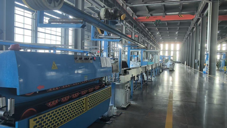
The cable construction is fundamentally different from the simpler low-voltage NYY family. The defining technology is triple extrusion — the inner semi-conducting layer, the XLPE main insulation, and the outer semi-conducting layer are extruded simultaneously through three concentric dies in a single production pass. This eliminates the voids and interface defects that would otherwise initiate partial discharge under the high voltage stress, and is what allows the cable to operate reliably for 30 to 40 years at 8.7/15 kV or higher. Above the triple-extruded core is a copper tape metallic screen (for short-circuit current carrying and earth-fault path), then for three-core cables an inner PVC sheath and rubber-compatible filler, then optional steel-tape or steel-wire armour, and a red PVC outer sheath as the standard international identification colour for medium-voltage cable.
Production follows IEC 60502-2 as the primary international reference, with parallel certifications to BS 6622 (UK 6-33 kV), BS 7835 (UK 11-33 kV LSZH), DIN VDE 0276-620 (Germany), HD 620 S1 (CENELEC harmonised European), AS/NZS 1429.1 (Australia/NZ), and additional regional standards on request. Jinda manufactures the YJLV / NA2XSY family on dedicated medium-voltage production lines with triple-extrusion heads, partial-discharge test stations, and dry-cure CV-line vulcanisation. Standard lead time is 25 to 45 days depending on voltage class and quantity; utility-scale projects ship through Tianjin, Qingdao, and Shanghai ports in container-load or break-bulk configurations.
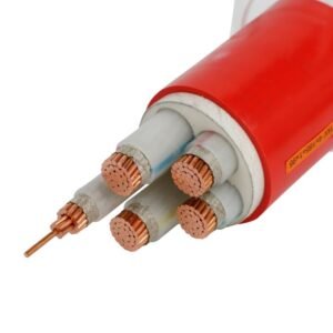
Cable Structure
Nine Layers, Triple Extrusion, Decades of Refinement
Medium-voltage cable construction is meaningfully more complex than low-voltage cable because the higher voltage stress demands careful electric-field management. The defining technology is the triple-extruded conductor screen / XLPE insulation / insulation screen sandwich — the three layers are extruded simultaneously through concentric dies in a single pass to eliminate the voids and interfaces that initiate partial discharge. The nine-layer construction below is what makes IEC 60502-2 cable rated for 30-40 year service life at voltages where simpler low-voltage construction would fail within months.
-
1
Conductor — Class 2 Stranded Compacted Aluminium (or Copper)
Hard-drawn aluminium per IEC 60228 Class 2 for YJLV, plain annealed copper per IEC 60228 Class 2 for YJV. Stranded and compacted to a circular profile (RM/CM) for sizes 25 to 800 mm², with sector-shaped (SM) construction available for three-core configurations to reduce overall cable diameter. The compacted construction eliminates interstrand air gaps that would otherwise create voltage stress concentrations under the inner semi-conducting screen.
-
2
Conductor Screen — Extruded Semi-Conducting Compound (Triple Extrusion Layer 1)
Extruded layer of semi-conducting cross-linkable compound applied directly over the conductor to smooth out the electric field at the conductor surface and eliminate stress concentrations at individual strand surfaces. Bonded tightly to the conductor and to the XLPE insulation above it — no air gaps or interfaces where partial discharge could initiate. Wall thickness typically 0.4 to 1.0 mm depending on cable voltage class.
-
3
Main Insulation — Cross-Linked Polyethylene XLPE (Triple Extrusion Layer 2)
Extruded XLPE main insulation, cross-linked to thermosetting properties via peroxide cure in a continuous-vulcanisation (CV) line. Insulation wall thickness defined precisely by IEC 60502-2 for each voltage class — 3.4 mm for 8.7/15 kV, 5.5 mm for 12/20 kV, 8.0 mm for 18/30 kV. Rated for 90°C continuous conductor temperature, 130°C emergency overload, and 250°C short-circuit (5 seconds). The thermal headroom over PVC insulation translates to 30-40 percent higher ampacity at the same cross-section.
-
4
Insulation Screen — Extruded Semi-Conducting Compound (Triple Extrusion Layer 3)
Extruded layer of semi-conducting compound on the outer surface of the XLPE insulation — mirrors the conductor screen function on the outside. Bonded firmly to the XLPE during the same triple-extrusion + CV-cure process so there’s no interface for partial discharge to initiate. For practical maintenance, the outer screen is “strippable” (peelable cleanly from the insulation) on most modern cables to allow joint and termination preparation.
-
5
Water-Blocking Layer — Semi-Conducting Swellable Tape
Semi-conducting tape with hygroscopic powder that swells on contact with moisture — blocks longitudinal water ingress if the cable sheath is damaged. Particularly important for buried cable installations where ground water could otherwise wick through the cable for kilometres after a single sheath puncture, requiring replacement of the entire cable run.
-
6
Metallic Screen — Copper Tape (CTS) or Copper Wires
Helical-wrapped copper tape (CTS, copper tape screen) typically 25 to 75 mm wide with 15 to 20 percent overlap, or for single-core cables, concentric copper wire screen with helical binder tape. Sized to carry the full earth-fault current of the network for the specified clearing time (typically 1 to 3 seconds) without overheating — the cross-sectional area is project-specific and called out in the cable schedule. This is not an EMI shield like KVVP; it’s a fault-current path designed to operate the upstream protection during an insulation failure.
-
7
Inner Sheath (Three-Core Cables) — Extruded PVC Bedding
For three-core configurations, the three screened cores are cabled together with rubber-compatible filler and a binder tape, then an extruded PVC inner sheath provides the circular bedding for any subsequent armour. Single-core cables skip this layer because there’s only one core to sheath. For unarmoured single-core, the inner sheath is also omitted and the outer sheath is applied directly over the metallic screen.
-
8
Armour (Optional) — Steel Tape (STA) / Steel Wire (SWA) / Aluminium Wire (AWA)
For armoured variants, the cable is wrapped with double steel tape (YJLV22 / NA2XSEBY — STA, the most common armouring for direct-burial three-core installations) or steel wire (YJLV32 / NA2XSERY — SWA, for vertical risers and high-mechanical-stress environments). Single-core cables for AC service use non-magnetic aluminium wire armour (AWA) to avoid the eddy current losses that would occur with steel armour around AC single-conductor magnetic fields.
-
9
Outer Sheath — PVC (Standard Red) or HDPE / LSZH (Special Variants)
Extruded PVC outer sheath per IEC 60502-2 Type ST2, with the international standard red colour for medium-voltage cable identification — distinguishes the cable from black low-voltage NYY in shared cable trenches and trays. For projects requiring tougher mechanical protection or better chemical resistance, HDPE (high-density polyethylene) outer sheath is available. For fire-safety installations in tunnels, metro stations, and public buildings, LSZH (low-smoke halogen-free) outer sheath is available per BS 7835 specification. Anti-termite and anti-rodent compounds available on quotation for tropical and rural installations.
Key Features
What Makes a Medium-Voltage Cable Different From a Low-Voltage Cable
The features below are not about marketing claims — they are the specific engineering provisions that distinguish a real IEC 60502-2 medium-voltage cable from low-voltage cable simply labelled with a higher voltage rating. Each of these is essential for 30+ year service life at 8.7/15 kV or above; missing any one of them produces a cable that may pass factory acceptance tests but fails in service from partial discharge, water treeing, or fault-current heating damage.
Triple Extrusion Eliminates Partial Discharge
The conductor screen, XLPE main insulation, and insulation screen are extruded simultaneously through three concentric dies in a single production pass — not as separate layers applied sequentially. The three layers bond together without interfaces, voids, or contamination that would otherwise initiate partial discharge under voltage stress. Partial-discharge tests at factory acceptance verify the cable has zero detectable discharge above background noise — the test that separates real MV cable from poorly-made imitations.
90°C XLPE = 30-40% Higher Ampacity vs PVC
XLPE insulation rated for 90°C continuous conductor temperature, 130°C emergency overload (typically 100 hours per year), and 250°C short-circuit for 5 seconds. The thermal headroom over the 70°C PVC insulation in low-voltage NYY translates to roughly 30-40 percent higher steady-state ampacity at the same cross-section. For utility distribution networks where conductor cost is dominant, that ampacity advantage justifies the premium for XLPE construction.
Voltage Classes 3.6/6 kV Through 26/35 kV
The full IEC 60502-2 voltage range available from a single product family: 3.6/6 kV (light industrial), 6/10 kV (urban distribution), 8.7/15 kV (the most popular global MV class), 12/20 kV (utility primary distribution), 18/30 kV (sub-transmission, wind farms), 21/35 kV and 26/35 kV (higher utility distribution). Each voltage class has specific insulation wall thickness and screen specifications per the IEC table — specify the project voltage class precisely, not a generic “MV cable”.
Copper Screen for Earth Fault, Not EMI
The copper tape or copper wire screen over the insulation is sized to carry the network earth-fault current for the specified clearing time (typically 1 to 3 seconds at 10 to 25 kA depending on the network design). This is fundamentally different from the EMI-rejection screen in control cables — the MV cable screen is a fault-current path that operates the upstream protection during an insulation failure, not a noise-rejection layer. The screen cross-sectional area is project-specific; specify the fault-current rating at order so the screen is sized correctly.
Red Sheath = International MV Identification
Standard outer sheath colour is red for medium-voltage cable across all major international markets — the universal visual identification that distinguishes MV cable from the black low-voltage NYY/NAYY that shares the same cable trenches and trays in many installations. The colour convention prevents catastrophic misconnection where a low-voltage circuit would be wired into a medium-voltage termination by mistake. Other colours (black, blue, grey) available on quotation for projects with specific identification requirements.
IEC + BS + VDE + HD + AS/NZS Multi-Market Certified
Production certified to IEC 60502-2 as primary international reference, plus BS 6622 (UK 6-33 kV), BS 7835 (UK 11-33 kV LSZH), DIN VDE 0276-620 (Germany), HD 620 S1 (CENELEC harmonised European), AS/NZS 1429.1 (Australia/NZ). KEMA, BASEC, CESI, and SGS test reports available for utility-acceptance qualification. For projects exporting across multiple regulatory regimes, dual or triple certification on a single physical cable production run is straightforward — specify all target markets at order.
How to Choose
Six Decisions Before You Place the Order
Medium-voltage cable selection is meaningfully more complex than low-voltage NYY because the voltage class, screen current rating, single-core vs three-core construction, and armouring choice all interact with each other and with the network protection scheme. Get all six decisions right at order time — specification errors on MV cable typically cost 5 to 10 times more than equivalent errors on low-voltage cable, both in material and in retrofit installation cost.
Confirm the exact voltage class for the network
IEC 60502-2 defines voltage classes with specific insulation wall thicknesses: 3.6/6 kV (Um=7.2), 6/10 kV (Um=12), 8.7/15 kV (Um=17.5 — the most common worldwide), 12/20 kV (Um=24), 18/30 kV (Um=36), 21/35 kV and 26/35 kV (Um=40.5). Specify the project nominal voltage U₀/U (phase-to-earth / phase-to-phase) precisely — do not specify generic “15 kV” or “medium voltage”. Networks above 35 kV require IEC 60840 high-voltage cable, not IEC 60502-2.
Aluminium YJLV or copper YJV
YJLV / NA2XSY (aluminium conductor) is the dominant choice for utility distribution networks — 30-40 percent cheaper per equivalent ampacity than copper, with adequate performance for fixed-installation distribution feeders. YJV / N2XSY (copper conductor) is used in industrial installations where space is constrained (copper carries more amps per cross-section), in vibration environments where aluminium fatigue is a concern, and on shorter runs where the cable cost differential matters less. Utility companies almost universally specify aluminium; industrial customers often specify copper.
Single-core vs three-core construction
Three-core (one cable containing three insulated cores) for cross-sections up to 400 mm² — one cable to pull, one set of terminations to make, simpler installation. Single-core (three separate cables pulled in trefoil formation) for cross-sections above 400 mm² where three-core construction becomes physically unwieldy, or for the highest currents above ~600 A where single-core gives better thermal performance. Single-core also dominates wind farm and solar farm collector installations where the parallel-cable configuration matches the layout.
Armouring: none / STA / SWA / AWA
Unarmoured YJLV / NA2XSY for cable-tray and conduit installations indoors. YJLV22 / NA2XSEBY (double steel tape armour) for direct-burial three-core cables — the standard for buried utility distribution. YJLV32 (steel wire armour) for vertical riser cables and harsh mechanical environments. For single-core AC cables, specify aluminium wire armour AWA instead of steel — the alternating magnetic field around a single AC conductor induces eddy current losses in steel armour that would overheat the cable; non-magnetic aluminium armour avoids this problem.
Specify the metallic screen cross-section
The copper tape or wire screen must carry the network earth-fault current for the protection clearing time without overheating. Specify both the fault current (typically 10 to 25 kA depending on network design) and the clearing time (typically 1 to 3 seconds based on the upstream protection). The required screen cross-section is calculated from these — typical values are 16, 25, 35, or 50 mm² equivalent copper. Under-specified screen damages from a single earth fault; over-specified screen wastes copper and increases cable diameter unnecessarily.
Target-market certification and fire performance
For most international markets, IEC 60502-2 certification is the universal acceptance reference. For UK projects, add BS 6622 (general MV) or BS 7835 (LSZH variant for transit and public buildings). For German and Northern European projects, add DIN VDE 0276-620. For Australian and NZ projects, AS/NZS 1429.1 with RCM mark. For tunnels, metro stations, and public buildings under fire-safety codes, specify LSZH outer sheath per BS 7835. For European CPR compliance, specify the required CPR class (typically Eca for utility, Dca or higher for public buildings).
Applications
Where Medium-Voltage Distribution Actually Happens
YJLV / NA2XSY appears in every utility distribution network, every large industrial plant, and increasingly in renewable energy collector networks worldwide. The four scenarios below cover the dominant high-volume applications driving global MV cable demand. Each scenario calls for slightly different voltage class, armouring, and screen configuration — specify the application context at order so we deliver the right cable spec for the installation, not a generic 8.7/15 kV product.
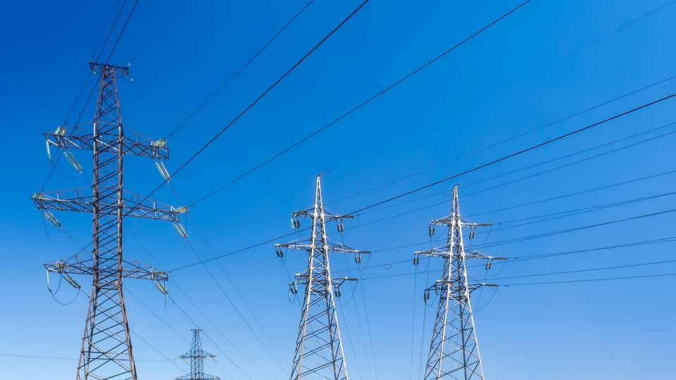
Urban Utility Distribution Networks
Primary distribution from substation 11/22/33 kV switchgear out to local distribution transformers. Typically YJLV22 three-core 3×95 to 3×240 mm² aluminium at 8.7/15 kV or 12/20 kV, direct-buried in concrete-encased ducts or in trenches with sand bedding. The dominant cable on urban distribution networks worldwide — billions of metres in service across European, North American, Asian, African, and Latin American utility networks.

Wind Farm Collector Networks
Inter-turbine cabling from each wind turbine MV transformer back through the collector network to the project substation. Typically single-core YJLV with AWA aluminium-wire armour at 18/30 kV or 21/35 kV, sized from 95 mm² (closest turbines) up to 630 mm² (collector trunk feeders into the substation). Direct-buried for the entire collector network with cathodic protection considerations and water-blocking tape specifications.
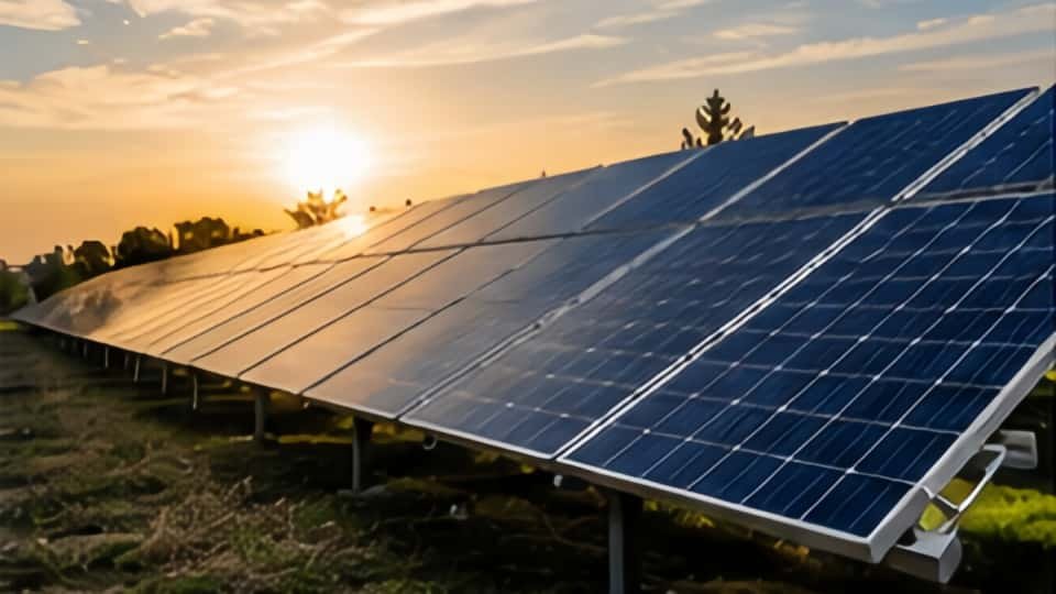
Solar Farm Collector Networks
Inverter station MV outputs to the project substation collector. Typically YJLV22 three-core 3×120 to 3×300 mm² aluminium at 12/20 kV or 18/30 kV, direct-buried between inverter stations and the substation. Lower current per cable than wind farms (solar inverter sizes typically 1-5 MW vs wind turbine 3-15 MW) but more cables per project due to distributed inverter architecture.
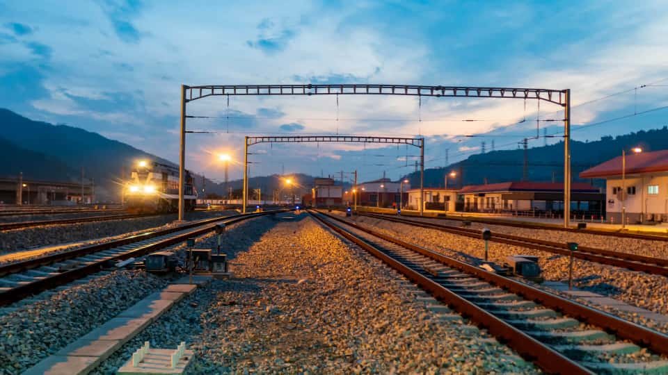
Industrial & Transit MV Supply
Industrial plant primary supply from utility incoming substation to plant MV switchgear (steel mills, refineries, chemical plants, large data centres); metro and railway traction power feeders at 15 kV or 25 kV AC; airport substation interconnects; large data centre and hospital primary supply where loads exceed the practical LV cable limit. Typically copper-conductor YJV / YJV22 for industrial installations where ampacity per cross-section matters; LSZH outer sheath for metro and railway under fire-safety codes.
Not appropriate for: Low-voltage distribution at 0.6/1 kV (use NYY / NAYY or N2XY instead — MV cable is significantly more expensive and the extra performance is wasted). High-voltage transmission above 35 kV (use IEC 60840 HV cable instead — YJLV is rated only up to 26/35 kV). Submersible or continuous-water-immersion installations without water-blocked variant (specify the longitudinal water-blocked construction). Continuous flexing in cable carriers (use dedicated reeling cable). Direct burial without armouring (use the YJLV22 or YJLV32 armoured variants). Mobile mining installations (use the MYJV mining cable family). Single-core AC cables with steel armour (always specify aluminium wire armour AWA to avoid eddy current losses).
Technical Data
YJLV 3-Core 8.7/15 kV Standard Sizes
Reference values for 3-core YJLV (Al/XLPE/CTS/PVC, 8.7/15 kV) per IEC 60502-2. The 8.7/15 kV class is the most popular medium-voltage rating worldwide and covers the bulk of utility distribution applications. Ampacity values are per IEC 60287 installation method — direct buried in soil, 90°C conductor temperature, 20°C ground temperature, 1.0 K·m/W soil thermal resistivity, three-cables-in-trefoil grouping. Apply derating factors per IEC 60287 for installation in conduit, grouped circuits, non-standard soil resistivity, or different ground temperatures. Other voltage classes (3.6/6, 6/10, 12/20, 18/30, 26/35 kV), single-core variants, and copper-conductor YJV equivalents available on request — specify the project voltage class precisely at order.
| Cores & Size | Conductor Construction | Approx. Cable OD | DC Resistance (max, 20°C) | Ampacity (buried, 90°C cond.) | Approx. Weight |
|---|---|---|---|---|---|
| 3×25 mm² | Stranded compacted (CM) | ~ 38 mm | 1.20 Ω/km | 100 A | ~ 1,400 kg/km |
| 3×35 mm² | Stranded compacted (CM) | ~ 41 mm | 0.868 Ω/km | 120 A | ~ 1,700 kg/km |
| 3×50 mm² | Sector compacted (SM) | ~ 44 mm | 0.641 Ω/km | 145 A | ~ 2,050 kg/km |
| 3×70 mm² | Sector compacted (SM) | ~ 48 mm | 0.443 Ω/km | 180 A | ~ 2,500 kg/km |
| 3×95 mm² | Sector compacted (SM) | ~ 52 mm | 0.320 Ω/km | 215 A | ~ 3,050 kg/km |
| 3×120 mm² | Sector compacted (SM) | ~ 55 mm | 0.253 Ω/km | 245 A | ~ 3,600 kg/km |
| 3×150 mm² | Sector compacted (SM) | ~ 59 mm | 0.206 Ω/km | 275 A | ~ 4,200 kg/km |
| 3×185 mm² | Sector compacted (SM) | ~ 63 mm | 0.164 Ω/km | 310 A | ~ 4,950 kg/km |
| 3×240 mm² | Sector compacted (SM) | ~ 69 mm | 0.125 Ω/km | 360 A | ~ 6,100 kg/km |
| 3×300 mm² | Sector compacted (SM) | ~ 75 mm | 0.100 Ω/km | 410 A | ~ 7,300 kg/km |
| 3×400 mm² | Sector compacted (SM) | ~ 82 mm | 0.0778 Ω/km | 465 A | ~ 9,000 kg/km |
DC resistance per IEC 60228 hard-drawn aluminium Class 2, 20°C. Ampacity per IEC 60287 direct-buried installation in trefoil, 90°C conductor temperature, 20°C ground, 1.0 K·m/W soil thermal resistivity. For installation in air on cable tray, ampacity is approximately 10-15 percent higher due to better convective cooling. For grouped installation in multiple parallel circuits, apply derating per IEC 60287 grouping factors. For copper-conductor YJV equivalent, ampacity is approximately 25-30 percent higher at the same cross-section due to lower conductor resistance.
Insulation voltage: 8.7/15 kV per IEC 60502-2 (U₀/U — 8.7 kV phase-to-earth, 15 kV phase-to-phase; Um=17.5 kV). Insulation wall thickness: 3.4 mm nominal per IEC 60502-2 Table 4. Operating temperature: 90°C continuous conductor / 130°C emergency (max 100 hours per year) / 250°C short-circuit (5 seconds). Minimum bending radius: 15× OD for single-core / 12× OD for three-core (per IEC 60502-2). Standard outer sheath red PVC for global MV identification. CPR classification typically Eca for standard PVC sheath, Dca or higher for LSZH variant per BS 7835.
Comparison
YJLV vs Its Closest Alternatives in the MV Cable Family
The medium-voltage cable family has several closely-related variants and one important legacy alternative (paper-insulated lead-covered cable, PILC, still in service on older utility networks). The table below compares the five most commonly evaluated specifications when planning a new MV installation. The defining choice is usually aluminium vs copper for conductor, three-core vs single-core for construction, and armoured vs unarmoured for installation environment.
| Attribute | YJLV (this product) | YJV (copper) | YJLV22 (armoured) | PILC (legacy paper) |
|---|---|---|---|---|
| Standard | IEC 60502-2 | IEC 60502-2 | IEC 60502-2 | Legacy (no current IEC) |
| International equiv. | NA2XSY / NA2XSEY | N2XSY / N2XSEY | NA2XSEBY / NA2XSBY | PILC, deprecated |
| Conductor | Aluminium (Class 2 strand) | Copper (Class 2 strand) | Aluminium (Class 2 strand) | Copper (Class 2 strand) |
| Insulation | XLPE (cross-linked PE) | XLPE (cross-linked PE) | XLPE (cross-linked PE) | Impregnated paper |
| Metallic screen | Copper tape (CTS) | Copper tape (CTS) | Copper tape (CTS) | Lead sheath |
| Armour | None | None | Double steel tape (STA) | Steel tape over lead |
| Voltage rating range | 3.6/6 to 26/35 kV | 3.6/6 to 26/35 kV | 3.6/6 to 26/35 kV | 3.6/6 to 18/30 kV |
| Conductor temp (continuous) | 90°C | 90°C | 90°C | 65-80°C |
| Ampacity at 3×95 mm² | ~ 215 A (buried) | ~ 275 A (buried) | ~ 215 A (buried) | ~ 180 A (buried) |
| Direct burial | Use armoured variant | Use armoured variant | Yes | Yes |
| Cost (relative to YJLV) | 1.00 (baseline) | 1.40 to 1.60 (copper premium) | 1.15 to 1.30 (armour) | 2.0 to 3.0 (specialty) |
When to choose YJLV (this product)
Utility distribution networks, wind farm and solar farm collector cables, large industrial plant primary feeders, and any MV application where the 30-40 percent aluminium-vs-copper cost saving on the conductor matters at project scale. The dominant choice on global utility networks for the medium-voltage class. For unarmoured runs in cable tray or conduit; for direct-burial installations, step up to YJLV22 with steel tape armour.
When to choose an alternative
For industrial installations with space constraints, vibration concerns, or shorter cable runs where conductor cost matters less, step up to YJV / N2XSY copper conductor. For direct-burial installations, specify YJLV22 / NA2XSEBY with steel tape armour or YJLV32 with steel wire armour. For single-core AC installations, specify the variant with aluminium wire armour (AWA), not steel. For metro, railway, and public-building installations under fire-safety codes, specify the BS 7835 LSZH variant. For low-voltage distribution at 0.6/1 kV, use NYY / NAYY / N2XY instead — MV cable is significantly more expensive and overkill for LV applications. For high-voltage transmission above 35 kV, use IEC 60840 HV cable.
Frequently Asked Questions
Common Questions From Utility Engineers, EPC Contractors, and Project Buyers
What does YJLV stand for?
The YJLV cable code encodes the construction: Y = XLPE insulation, J = cross-linked (Jiaolian), L = aluminium conductor (Lu), V = PVC outer sheath. Common variants extend the code: YJV drops the L for copper-conductor variant. YJLV22 adds 22 for double steel-tape armour. YJLV32 adds 32 for steel-wire armour. Internationally, the European equivalents follow the VDE/CENELEC convention: NA2XSY = N (normal) + A (aluminium) + 2X (XLPE) + S (copper screen) + Y (PVC sheath); NA2XSEY adds E for concentric earth wire screen; NA2XSEBY is the three-core armoured variant. Both code systems describe the same physical cable construction.
Is YJLV the same cable as NA2XSY?
Functionally equivalent at the construction level. YJLV per the Chinese / IEC code and NA2XSY per the European VDE/CENELEC code describe the same physical cable: aluminium conductor + triple-extruded XLPE insulation with semi-conducting screens + copper tape metallic screen + PVC outer sheath at IEC 60502-2 voltage classes. Most production lines run the cable to multiple certifications simultaneously — the dimensional and electrical parameters are identical, the test methods are aligned, and the cable can be marked with both code systems on the same physical product. For projects accepting either Chinese / IEC or VDE marking, specify both certifications at order so the cable can be deployed regardless of which authority inspects the installation.
Why is the metallic screen copper tape and not copper braid?
This is one of the most common misconceptions about MV cable. The copper screen in YJLV is fundamentally different in function from the copper braid in control cable like KVVP. The KVVP braid screen is for EMI / RFI rejection — intercepting electromagnetic interference at signal frequencies (kHz to MHz). The YJLV copper tape screen is for short-circuit fault-current carrying — providing a low-impedance earth path to operate the upstream protection (typically a 10-25 kA fault for 1-3 seconds during an insulation failure). Copper tape gives 100% coverage and the cross-section needed to carry fault current without overheating; copper braid wouldn’t survive the thermal load even at 85% coverage. Copper wire screen (concentric stranding) is also used for some single-core variants where the wire construction better suits the cable geometry.
Why must single-core MV cable use aluminium wire armour instead of steel?
AC current in a single conductor creates an alternating magnetic field around the cable. If this field passes through ferromagnetic material (steel armour), it induces eddy currents in the steel that dissipate as heat — the cable runs hot and the ampacity must be derated significantly to compensate. For multi-core cables, the magnetic fields from the three phase conductors cancel out vector-sum at the armour radius and steel armour works fine. For single-core AC cables, there’s no field cancellation, so the armour must be non-magnetic — aluminium wire armour (AWA) or non-magnetic stainless steel wire. Specifying steel armour on a single-core MV cable is one of the most expensive mistakes possible in MV cable engineering; verify the armour spec carefully at order time for any single-core AC installation.
What is triple extrusion and why does it matter?
Triple extrusion means the inner semi-conducting screen, the XLPE main insulation, and the outer semi-conducting screen are extruded simultaneously through three concentric dies in a single production pass — not as three separate layers applied sequentially. The three layers bond together as a continuous matrix without interfaces, voids, contamination, or interlayer separation that would otherwise concentrate electric field stress and initiate partial discharge. Sequentially-applied screens (older or cheaper manufacturing) have inevitable interface defects that grow into partial discharge sites under voltage stress and eventually fail the insulation. For 8.7/15 kV and higher voltage classes, triple extrusion is essential for 30+ year service life; non-triple-extruded MV cable may pass factory tests but typically fails in service within months to years.
What is the typical lead time and MOQ?
Medium-voltage cable production runs slower than low-voltage NYY because of the triple-extrusion + CV-cure process, the partial-discharge testing at acceptance, and the typically larger cable diameters. Standard YJLV configurations at 8.7/15 kV in common cross-sections (3×95 to 3×240 mm²) typically ship in 25–45 days from order. Higher voltage classes (18/30 kV+) and larger cross-sections take 35-60 days. Armoured variants add 7-10 days for the armouring pass. Multi-market certification (combining IEC + BS + VDE) adds 5-10 days for documentation processing and witness testing. MOQ is normally 1,000 m per cable specification due to the long machine setup time for MV production; smaller trial orders accepted with surcharge. For utility-scale projects ordering 20+ km in a single voltage class and cross-section, dedicated production runs deliver the best unit pricing and quality consistency.
Installation & Handling Tips
Six Practices That Separate 30-Year MV Cable From 5-Year Failures
MV cable installation is meaningfully more technical than low-voltage NYY because the higher voltage stress makes every termination defect, every contamination point, and every cable handling error potentially catastrophic. The six practices below cover the field-level details that consistently separate properly-installed MV cable with full 30-40 year service life from installations that fail prematurely from partial discharge, water ingress, or termination breakdown. These practices apply on top of strict adherence to manufacturer installation manuals and qualified MV jointer training.
Use only certified jointers for terminations
MV cable terminations and joints require specialised tools, training, and quality control beyond what general electrical contractors typically have. Use only jointers with manufacturer certification for the specific termination kit and cable type, working in clean conditions (covered work area, no dust, no humidity), with proper stress-cone preparation and semi-conducting screen termination. Most MV cable failures in the field trace back to defective terminations or joints, not to the cable itself.
Test partial discharge AND insulation resistance before energising
Pre-energisation testing for MV cable includes both insulation resistance (megger at 5 kV DC, expected > 1000 MΩ) and partial discharge measurement at AC voltage above the rated U₀. The PD test is specific to MV cable and detects insulation defects that megger testing alone misses. Document the PD test results in the project handover. Cables with detectable PD above background noise have insulation defects that will fail within months to years; replace before commissioning rather than energising a known defect.
Bond the metallic screen at one or both ends per the network design
For short cable runs (under a few hundred metres), bond the copper screen to earth at both cable ends — provides the lowest-impedance fault current path. For long single-core cable runs, use cross-bonding (screen continuity at intermediate joints with phase rotation) to control the standing voltage that would otherwise develop on the screen from the AC magnetic field. The bonding scheme is project-specific and should be designed in advance by the network engineer — do not leave it to installation discretion.
Maintain minimum bending radius during pulling
MV cable minimum bending radius is 15× OD for single-core and 12× OD for three-core (per IEC 60502-2). Tighter bends during cable pulling damage the XLPE insulation and the semi-conducting screen interfaces invisibly from outside but cause partial discharge initiation over months in service. Use proper cable rollers at corners during pulling, never manual force around tight bends. For very large cables (300 mm²+), use cable-pulling equipment with calibrated tension monitoring — over-tension stretches the conductor and damages the insulation.
Route single-core circuits in trefoil formation
For three single-core cables forming a three-phase circuit, route them in equilateral trefoil formation (the three cables touching at the centre of a triangle) rather than flat side-by-side spacing. Trefoil minimises the AC inductance, reduces the cable losses, balances the impedance between phases, and keeps the magnetic field cancellation effective at the cable group radius. Flat formation works but requires phase rotation along the run and produces higher losses. Strap the trefoil bundle at regular intervals (typically 1-2 m) to maintain the formation under thermal cycling.
Seal cable ends to prevent water ingress during construction
Water ingress is the primary long-term failure mechanism for MV cable. The water-blocking semi-conducting tape inside the cable is the last line of defence, not a substitute for proper end sealing. During construction, always cap cable ends with heat-shrink end caps immediately after cutting and before backfilling trenches. For cable runs awaiting termination, apply waterproof end caps and elevate the cable ends above ground level. Moisture trapped inside the cable during construction sits there for years and slowly degrades the XLPE insulation from the inside, causing water treeing and eventual breakdown.
Safety note: Medium-voltage cable installation must comply with the applicable network operator standards (typically national utility specifications), national wiring codes, and IEEE / IEC installation guidelines. The cable’s voltage rating (8.7/15 kV, 18/30 kV, etc.) is immediately lethal at any unprotected conductor exposure — never approach an MV cable assumed to be de-energised without verified isolation, earthing, and lockout procedures per the network operator’s safety rules. Only personnel with formal MV authorisation should handle live or recently de-energised MV cable. For energisation, complete the partial discharge and insulation resistance acceptance tests, verify all terminations and joints, confirm the earthing scheme, and follow the network operator’s commissioning protocol. Documentation of all tests and verifications becomes the baseline for future maintenance.
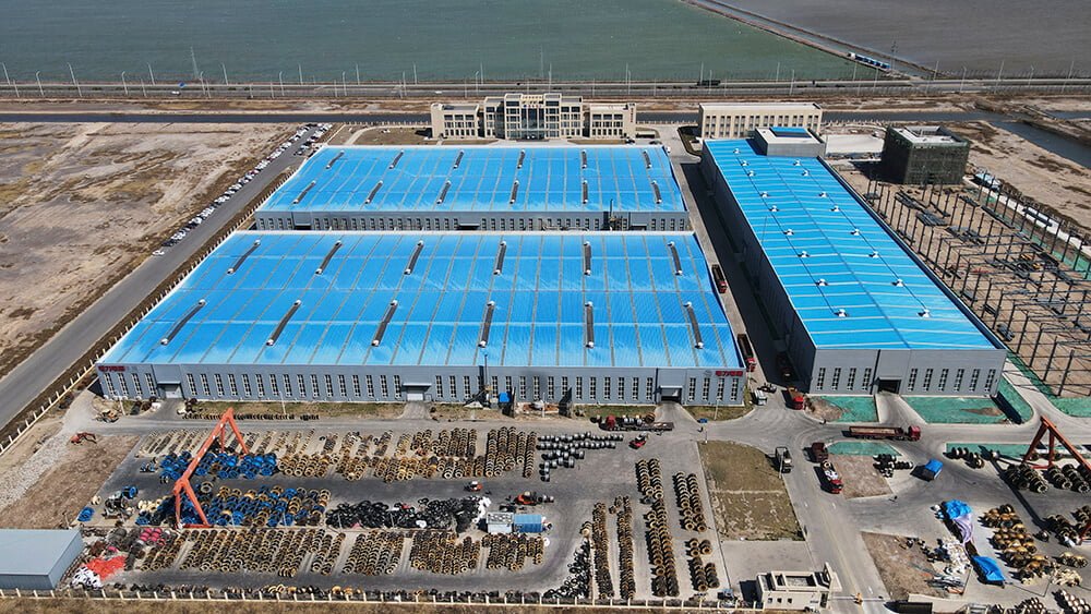
Manufacturing Capability
Why Source From Jinda Cable
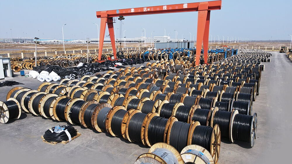
Behind every drum we ship sits a 38-year track record, five production bases under one MES system, and a documentation discipline that gets cables through customs without delays.

-
Every cable tested twice before shipping
Since 1987, our two-stage QC has been refined to a science: routine test on the production line, then full electrical and mechanical re-test before packing. Across 50+ export markets, our return rate stays under 0.3%.
-
Five production bases, 470,000 m², synced via MES
Tianjin, Liaoning, Heilongjiang, Shandong, and Xian — each base runs under one unified MES system. Same recipe, same protocols, same traceability, regardless of which plant ships your order.
-
3,000+ SKUs, custom configurations welcome
Standard sizes ship from inventory. Special voltage grades, color-coding, drum lengths, or armor configurations are routine — submit your spec and our team will quote the lead time honestly.
-
Trusted by EPC contractors in 50+ countries
We supply utilities, mining operators, port authorities, and large industrial OEMs across Europe, the Americas, Southeast Asia, the Middle East, and Africa.
-
Full paperwork shipped with every order
Every shipment includes factory test report, certificate of origin (COO), packing list, and bill of lading (B/L). Customer-nominated witness testing can be arranged before shipment.
Our Track Record
98.7%
On-time shipment rate (last 24 months)
< 0.3%
Return rate across export markets
25 days
Typical sea freight Tianjin → Rotterdam
100%
Shipments with routine test report attached
Logistics & Delivery
Packaging, Shipping & Documentation
What we handle on our side from production floor to the port of loading. Product-specific installation guidance is supplied with the datasheet that accompanies each order.
Packaging
- Wooden or steel drums per IEC 62004
- Coil packaging available for small cross-sections
- Standard drum lengths plus custom lengths on request
- Each drum labeled with type, voltage, cross-section, length, batch
- Waterproof wrapping for export shipments
- Cable ends sealed against moisture ingress
- Private-label / OEM packaging available under NDA
Shipping
- FCL / LCL sea freight, air freight on request
- Trade terms: EXW, FOB, CFR, CIF, DDP
- Ports of loading: Tianjin / Qingdao / Shanghai
- Typical sea freight to Rotterdam: 25 days
- Lead time confirmed at order acknowledgement
- Container loading photos sent before sailing
Documentation
- Factory routine test report (per applicable standard)
- Commercial invoice and packing list
- Certificate of origin (CO) — China Council, FORM A, FORM E available
- Bill of lading (B/L) — original or telex release
- Third-party inspection by SGS / BV / TÜV on request
- Customer-nominated witness testing arranged before shipment
Get in Touch
Request a Quote for
Medium Voltage XLPE Insulated Power Cable YJLV
What You'll Receive
- Technical quotation with itemized FOB / CIF pricing
- Sample factory test report from a previous shipment
- Realistic lead time including raw-material procurement
- Direct contact with the assigned sales engineer


Email
info@jindacablegroup.comResponse Time
Within 1 business day
Related Products