/ 450/750V
Shielded Control Cable
Model: KVVP / Shielded Instrument Cable
Shielded control cable designed to minimize signal interference in sensitive control and instrumentation applications.
- Voltage Rating
- 450/750V
- Number of Cores
- Array
- Cross Section
- 0.75–10 mm²
- Conductor
- Copper
- Armoring
- Steel Tape Armored
- MOQ
- ≥ 100 m
Standards & Certifications
- GB/T
- GB/T 9330
Downloads
Specifications
Technical Specifications & Performance
Construction
- Model / Series
- KVVP / Shielded Instrument Cable
- Voltage Rating
- 450/750V
- Conductor Material
- Copper
- Conductor Class
- Class 2 Stranded
- Cross Section
- 0.75–10 mm²
- Number of Cores
- Array
- Insulation
- PVC
- Sheath
- PVC
- Armoring
- Steel Tape Armored
- MOQ
- ≥ 100 m
Performance
- Max. Conductor Temp.
- 70°C
- Min. Bending Radius
- 10 × Cable Outer Diameter
About This Product
The Signal-Integrity Workhorse of Industrial Automation
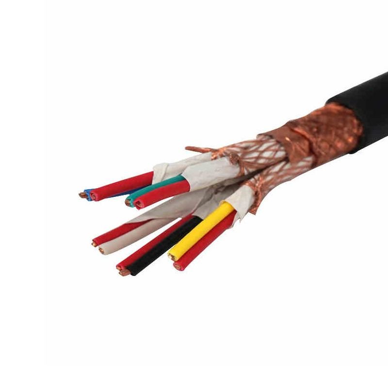
Shielded Control Cable (model designation KVVP per the Chinese national standard GB/T 9330 — K=control, V=PVC insulation, V=PVC sheath, P=shielded; with KVVRP for the flexible Class 5 variant, KYJVP for the XLPE-insulated variant, and internationally known as LiYCY per DIN VDE 0812 or YSLCY per DIN VDE 0250-602) is the universal multi-core signal cable for industrial control and instrumentation circuits. Where power cables move energy, this cable moves information — switching states, sensor readings, control commands, drive feedback, protection relay signals — through electromagnetically noisy environments without losing signal integrity.
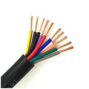
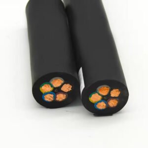
The defining feature is the tinned copper wire braid shield wrapped around all the conductors as a single overall screen, typically at 85 percent or higher coverage density. The shield captures induced electromagnetic interference (EMI) from nearby power cables, variable-frequency drives, switching power supplies, motors, and radio transmitters, and conducts it to ground rather than letting it couple into the signal conductors. Without shielding, control signals in a typical motor control center get corrupted within metres of running parallel to power cables; with proper shielding and earthing, the same circuits run reliably through the worst electromagnetic environments. Core counts run from 2 to 61 cores in a single cable — the defining difference from power cable, where 5 cores is large and 7+ is unusual.
Production follows GB/T 9330-2020 (the current Chinese national standard) plus IEC 60227 for international harmonisation. Export to European markets follows DIN VDE 0812 (LiYCY) or DIN VDE 0250-602 (YSLCY) — the same physical cable can be produced under multiple certifications for OEM customers serving global markets. Jinda manufactures the KVVP / LiYCY family at our Henan and Tianjin bases on dedicated control-cable production lines, with separate runs for screened and unscreened variants to prevent cross-contamination of the braid lines. Standard lead time is 18 to 28 days; supplied in 500 m or 1,000 m drums, with custom cut lengths available for OEM cabinet builders.
Cable Structure
Five Layers Engineered for Signal Integrity in Noisy Environments
Shielded control cable construction is fundamentally different from power cable. The defining requirement is not current capacity but signal integrity through electromagnetic interference — which drives the multi-core layered construction, the tinned-copper braid shield, the careful core identification scheme, and the rubber-compatible separator chemistry. Each layer plays a specific role in delivering clean signals from the field device to the control room.
-
1
Conductors — Class 2 Rigid (KVVP) or Class 5 Flexible (KVVRP)
Plain annealed copper per IEC 60228. KVVP uses Class 2 stranded copper (typically 7-strand for small cross-sections, 19-strand for 4-10 mm²) — rigid construction for fixed-installation control wiring in cable trays, conduits, and cabinets. KVVRP uses Class 5 fine-strand copper for cable trays with occasional re-routing or vibration. LiYCY and YSLCY always use Class 5 flexible — the European market expects flexibility as standard.
-
2
Insulation — PVC (KVVP) or XLPE (KYJVP)
Each core individually insulated. PVC insulation for the standard KVVP family — 70°C continuous service, low cost, mature manufacturing. XLPE insulation for KYJVP variants — 90°C continuous service, better insulation resistance, slimmer cable OD at the same voltage rating. Core identification follows GB/T 9330 (numbered or colour-coded per project requirement) or DIN 47100 for LiYCY (specific colour sequence with no repetition up to 36 cores, then numbered).
-
3
Core Lay-Up & Separator
Cores twisted into pairs (for LiYCY-TP twisted-pair variant) or into layers (standard KVVP) with a defined lay length tuned for flexibility and cross-talk suppression. PET (polyester) separator tape wraps over the cabled cores — provides mechanical separation between the cores and the shield, prevents the shield braid from biting into the core insulation during cable flexing.
-
4
Shield — Tinned Copper Wire Braid (TCWB) 85% Coverage
The defining feature of the P variant. Tinned copper wire braided helically over the separator tape at typically 85 percent geometric coverage density — the industry-standard minimum for effective EMI/RFI shielding at frequencies up to several MHz. Higher coverage (90-95%) available on request for installations near high-power VFDs or RF transmitters. The tinning prevents copper sulfide corrosion of the braid wires, which would degrade shield continuity over years of service. Alternative shield constructions: copper tape (P2 variant, 100% coverage, better at high frequencies but less flexible), or aluminium-foil + drain wire (lighter and cheaper, lower frequency range).
-
5
Outer Sheath — PVC (Standard) or LSZH (WDZ Variant)
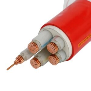
Extruded PVC outer sheath for the standard KVVP / LiYCY product — tough, oil-resistant, abrasion-resistant, flame-retardant per IEC 60332-1-2. Standard sheath colour is grey (the industrial-control standard colour, easily distinguished from black power cable in cable trays); other colours available on request. For installations requiring low-smoke halogen-free properties (data centres, metro stations, hospitals), specify the WDZ-KVVP variant with LSZH sheath. For steel-tape armored protection in direct-burial or harsh mechanical environments, specify KVVP2-22 (copper tape shield + steel tape armor + PVC outer sheath).
Key Features
What "Shielded Control Cable" Actually Has to Deliver
A shielded control cable in service is judged on signal integrity through electromagnetic environments — not voltage rating, not current capacity. The six features below are what GB/T 9330 and DIN VDE 0812 collectively guarantee, and what separates a real industrial control cable from cheap unshielded wire-bundle constructions that get sold as the same thing.
85% Tinned Copper Braid Shielding
The defining feature: tinned copper wire braid wrapped helically over the cabled cores at 85 percent geometric coverage density — the industry-standard minimum for effective EMI/RFI suppression up to several MHz. Higher densities (90-95%) available on request for severe noise environments (heavy VFD installations, large motors, radio transmission sites). The tinning prevents long-term braid corrosion in humid environments.
2 to 61 Cores in a Single Cable
Control cables routinely carry 24, 37, or even 61 individual conductors in a single jacketed cable — far more cores than typical 4-core or 5-core power cable. This is the defining selection feature for industrial control wiring: a PLC I/O panel with 24 digital inputs and 12 digital outputs needs a 37-core cable (24+12+1 PE) running back to the field, not 37 individual single-conductor cables. Saves cable tray space, installation time, and material cost.
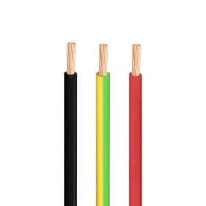
Clear Core Identification (Numbered or DIN 47100)
High-count multi-core cables need unambiguous core identification at termination time. GB/T 9330 standard: black-with-white-numbers (e.g., “1”, “2”, “3” through “37” printed on each core insulation) plus green-yellow earth. DIN 47100 standard (LiYCY): defined colour sequence with no colour repetition up to 36 cores, then numbered. Misidentified cores at the panel are the most common control cable installation defect — clear ID at the cable level prevents this.
450/750V Insulation, 24V to 230V Operating
KVVP and KYJVP rated 450/750V per GB/T 9330; LiYCY rated 300/500V per DIN VDE 0812. Actual operating circuits typically run at 24V DC (PLC I/O signals), 110V or 230V AC (control circuits, relay coils), or 4-20 mA (analog instrumentation) — the high insulation rating gives generous safety margin and tolerates control circuits that briefly transit through power-conductor voltages during fault conditions or maintenance.
Flame Retardant, Multiple Performance Grades
Standard KVVP per IEC 60332-1-2 (single-cable flame test). For cable-tray installations with multiple cables bundled, specify the ZR-KVVP flame-retardant variant per GB/T 19666 / IEC 60332-3-22 (Category A bundled-cable test). For data centres, hospitals, and underground stations, specify the WDZ-KVVP low-smoke halogen-free variant per GB/T 19666 + IEC 60754 + IEC 61034. Specify the required fire-performance class at order — the production line setup varies.
CCC, VDE, BS, CE Multi-Market Certified
KVVP per GB/T 9330-2020 with CCC certification for the Chinese domestic market. LiYCY per DIN VDE 0812 for the German and European market. YSLCY per DIN VDE 0250-602 for the broader European industrial automation market. BS 5308 for UK and Commonwealth instrumentation applications. CE marking under the Low Voltage Directive available on request alongside the standard certifications. For OEMs supplying global markets, dual or triple certification on a single cable is the norm.
How to Choose
Six Decisions Before You Place the Order
Control cable selection is dominated by core count, insulation choice, shielding density, and target-market certification. Get the core count right with a couple of spare conductors for future expansion (running a new multi-core cable is expensive; adding spare cores at original-order time is nearly free). Specify shielding only where it’s actually needed — over-specified shielded cable in low-EMI environments is wasted money.
Confirm you actually need shielding
Shielding adds cost (typically 15 to 30 percent over unshielded KVV/KVVR) and installation complexity (the shield must be earthed correctly at one end to be effective). Specify the shielded P variant only when the cable will run near power cables, motors, variable-frequency drives, RF transmitters, or other EMI sources — or when carrying low-level signals (4-20 mA analog, RTD temperature sensors, PLC digital I/O) that are vulnerable to induced noise. For purely 24V or 230V digital control circuits inside a clean control room, unshielded KVV may be sufficient.
Pick the right insulation: PVC or XLPE
PVC (KVVP, KVVRP) is the universal default — 70°C continuous service, lower cost, mature manufacturing, easier to strip and terminate. Sufficient for the vast majority of indoor industrial automation, machine tool, and process control applications. XLPE (KYJVP) is the upgrade for higher-temperature service — 90°C continuous, slimmer cable OD at the same voltage rating, better insulation resistance. Specify XLPE for cable runs through high-temperature areas (near furnaces, boiler rooms, glass manufacture, steel mills) or for cables that may briefly transit through 90°C environments during process upsets.
Size the core count with spare capacity
Add 15 to 25 percent spare cores beyond the immediate requirement. A 24-input PLC needs 24+E (typically a 27 or 30-core cable); spec the 37-core cable instead and you get 13 spare conductors for future expansion or replacing damaged conductors. Standard core counts: 2, 3, 4, 5, 7, 8, 10, 12, 14, 16, 19, 24, 27, 30, 37, 44, 48, 52, 61. Custom counts available but add cost; specifying a standard count is much cheaper. The cost difference between a 24-core and 37-core cable is typically only 25-35 percent on a per-metre basis but the spare cores save 5-10 times that cost on future repairs.
Pick the cross-section: 0.75 / 1.0 / 1.5 / 2.5 mm²
0.5-0.75 mm² for analog signal transmission (4-20 mA loops, RTD sensors, thermocouples, low-current digital I/O). 1.0-1.5 mm² for typical PLC digital I/O and 24V control circuits — the highest-volume sizes for industrial automation. 2.5 mm² for higher-current control circuits, relay coil supplies, longer cable runs requiring lower voltage drop. 4-10 mm² for low-frequency switching circuits and small motor control where the cable is doing power-cable-like work in a control cable configuration. Mixed cross-sections in a single cable are possible but add cost — specify one cross-section for all cores when possible.
Choose the right shield: braid vs tape vs foil
Tinned copper wire braid (standard P, 85% coverage) — the universal default. Flexible, effective up to several MHz, robust. Copper tape (P2, 100% coverage) — better high-frequency shielding, less flexible, used for VFD output cables and high-EMI environments. Aluminium-foil + drain wire (lighter, cheaper) — basic shielding for low-frequency installations and cost-sensitive bulk projects. Combined foil + braid (premium) — best-in-class shielding for the most demanding applications, used in semiconductor fabs and broadcast facilities.
Decide on fire performance & certification
Standard KVVP per IEC 60332-1-2 single-cable test — sufficient for most installations. ZR-KVVP (flame retardant Category A) for cable-tray bundled installations per GB/T 19666 / IEC 60332-3-22. WDZ-KVVP (low-smoke halogen-free) for data centres, hospitals, metro stations, and any installation where smoke and toxic gas during fire is a concern — mandatory under most modern building codes for public-access spaces. For export to Europe, specify CPR Eca or higher classification per EN 50575. For UK projects, BS 5308 instrumentation cable certification is the relevant reference.
Applications
Anywhere Signals Have to Travel Through Electrical Noise
Shielded control cable is the universal signal-integrity solution across industrial automation, building services, and infrastructure projects. The four scenarios below cover the dominant demand drivers; the underlying cable construction is the same across them, only the cross-section, core count, and certification regime varies by project. Annual demand for control cable across all industries combined exceeds the demand for any single category of power cable.
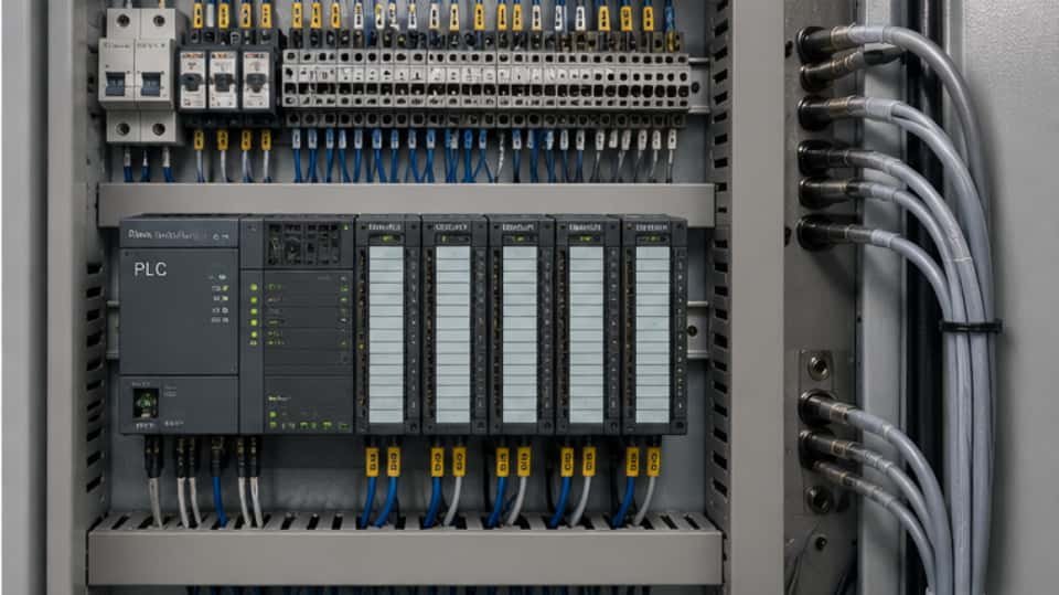
Industrial Automation & PLC Systems
Factory automation panels, PLC I/O cabling, variable-frequency drive control signals, conveyor system controls, machine tool electrical cabinets, robotic cell controls. Typically 7-37 cores 0.75-1.5 mm² for I/O panels; 4-core 1.5-2.5 mm² for VFD signal cables. Shielding is non-negotiable here — VFDs are aggressive EMI sources that overwhelm unshielded signal cables within metres.

Process Plant Instrumentation
Chemical plants, oil & gas refineries, power generation stations, water treatment, food & beverage processing. 4-20 mA analog loops, RTD and thermocouple temperature sensors, pressure transmitter signals, flow meter cabling. Typically 2-pair to 24-pair twisted-pair LiYCY-TP or BS 5308 individual + overall shielded variants. Long cable runs (often 200-500 m) through electrically noisy plant areas mandate proper shielding.
Substation Protection & Switchgear Control
Electrical substation protection relay wiring, circuit-breaker control cables, transformer monitoring, switchyard SCADA cabling, RTU connections. Typically 4-37 cores 1.5-2.5 mm² KVVP or KVVP2-22 (armored for buried cable runs between switchgear buildings). The high-voltage switchyard environment generates aggressive transient EMI — shielding plus proper earthing at one end is essential for protection-relay signal integrity.

Building Automation, Transit & Lifts
HVAC building automation systems, BMS sensor and actuator wiring, fire alarm and access control panels, metro and railway signalling systems, elevator and escalator control cables, traffic signal controllers, airport baggage handling controls. WDZ-KVVP low-smoke halogen-free variant is mandatory for transit and public-access installations under most modern building codes.
Not appropriate for: Power distribution (use YJV, WDZ-YJY, or YJV22 armored power cable). High-speed industrial Ethernet beyond Cat 5e/6 requirements (use dedicated PROFINET / EtherCAT industrial Ethernet cable). Outdoor permanent installation with UV exposure (use UV-stabilised outdoor variants or run inside conduit). Direct burial without armor (use KVVP2-22 armored variant). Mobile/flexing reeling applications (use dedicated reeling cable with strain-relief construction). Mining underground (use MCP / MYPT mining trailing cable with MT 818 compliance). Coal mine intrinsic-safety circuits (use dedicated MHYV / MHYV22 explosion-proof communications cable).
Technical Data
KVVP 1.5 mm² Standard Core Counts & Cable Dimensions
Reference values for KVVP 1.5 mm² control cable per GB/T 9330-2020 at 450/750V with tinned copper braid shield (85% coverage). The 1.5 mm² cross-section covers the bulk of PLC I/O and digital control wiring demand. Other cross-sections (0.5, 0.75, 1.0, 2.5, 4, 6, 10 mm²) and core counts up to 100+ are quoted alongside on request. LiYCY equivalents in DIN 47100 colour coding are available at 300/500V on the same physical cable construction.
| Core Count | Strand Construction | Approx. Cable OD | Shield Wire Count (TCWB) | DC Resistance (per core) | Approx. Weight |
|---|---|---|---|---|---|
| 2 × 1.5 mm² | 7 / 0.52 mm | ~ 7.8 mm | ~ 16 × 0.20 mm | 12.1 Ω/km | ~ 105 kg/km |
| 3 × 1.5 mm² | 7 / 0.52 mm | ~ 8.4 mm | ~ 16 × 0.20 mm | 12.1 Ω/km | ~ 130 kg/km |
| 4 × 1.5 mm² | 7 / 0.52 mm | ~ 9.0 mm | ~ 16 × 0.20 mm | 12.1 Ω/km | ~ 160 kg/km |
| 5 × 1.5 mm² | 7 / 0.52 mm | ~ 9.8 mm | ~ 24 × 0.20 mm | 12.1 Ω/km | ~ 195 kg/km |
| 7 × 1.5 mm² | 7 / 0.52 mm | ~ 10.6 mm | ~ 24 × 0.20 mm | 12.1 Ω/km | ~ 245 kg/km |
| 8 × 1.5 mm² | 7 / 0.52 mm | ~ 11.5 mm | ~ 24 × 0.20 mm | 12.1 Ω/km | ~ 280 kg/km |
| 10 × 1.5 mm² | 7 / 0.52 mm | ~ 12.4 mm | ~ 24 × 0.20 mm | 12.1 Ω/km | ~ 335 kg/km |
| 12 × 1.5 mm² | 7 / 0.52 mm | ~ 13.2 mm | ~ 24 × 0.20 mm | 12.1 Ω/km | ~ 390 kg/km |
| 14 × 1.5 mm² | 7 / 0.52 mm | ~ 14.0 mm | ~ 24 × 0.20 mm | 12.1 Ω/km | ~ 445 kg/km |
| 16 × 1.5 mm² | 7 / 0.52 mm | ~ 14.8 mm | ~ 24 × 0.20 mm | 12.1 Ω/km | ~ 500 kg/km |
| 19 × 1.5 mm² | 7 / 0.52 mm | ~ 15.6 mm | ~ 24 × 0.20 mm | 12.1 Ω/km | ~ 580 kg/km |
| 24 × 1.5 mm² | 7 / 0.52 mm | ~ 17.0 mm | ~ 24 × 0.20 mm | 12.1 Ω/km | ~ 715 kg/km |
| 30 × 1.5 mm² | 7 / 0.52 mm | ~ 18.6 mm | ~ 32 × 0.20 mm | 12.1 Ω/km | ~ 880 kg/km |
| 37 × 1.5 mm² | 7 / 0.52 mm | ~ 19.8 mm | ~ 32 × 0.20 mm | 12.1 Ω/km | ~ 1,065 kg/km |
| 44 × 1.5 mm² | 7 / 0.52 mm | ~ 21.5 mm | ~ 32 × 0.20 mm | 12.1 Ω/km | ~ 1,250 kg/km |
| 52 × 1.5 mm² | 7 / 0.52 mm | ~ 23.0 mm | ~ 32 × 0.20 mm | 12.1 Ω/km | ~ 1,460 kg/km |
| 61 × 1.5 mm² | 7 / 0.52 mm | ~ 24.5 mm | ~ 32 × 0.20 mm | 12.1 Ω/km | ~ 1,705 kg/km |
DC resistance per IEC 60228 Class 2 stranded annealed bare copper, 20°C. Tinned copper braid shield wire count and diameter shown are typical — actual braid construction varies with cable OD to maintain ≥ 85 percent geometric coverage. For 0.75 mm² cores, resistance is 26.0 Ω/km; for 2.5 mm², 7.98 Ω/km. For Class 5 flexible variants (KVVRP, LiYCY), resistance values are approximately 5 to 8 percent higher than Class 2 due to the air gaps in fine-strand construction.
Insulation voltage: 450/750V (KVVP per GB/T 9330) or 300/500V (LiYCY per DIN VDE 0812). Operating temperature: PVC variants −15°C to +70°C, XLPE variants −25°C to +90°C, LSZH variants −15°C to +70°C. Minimum bending radius: 6× OD for KVVRP flexible / 12× OD for KVVP rigid (per GB/T 9330) / 6× OD for LiYCY (per VDE 0812). Standard sheath colour grey for industrial control identification. Flame test: IEC 60332-1-2 standard / IEC 60332-3-22 Cat. A for ZR variant / IEC 60754 + IEC 61034 for WDZ LSZH variant.
Comparison
The Control Cable Family Tree — Which Variant for Which Job
The GB/T 9330 control cable family has a systematic naming convention: K (control) + insulation code + sheath code + optional modifiers for shielding (P), armor (22 / 23), flexibility (R), and high temperature (YJ for XLPE). Plus the parallel European LiYCY / YSLCY family for export markets. The table below shows the five most commonly compared variants — pick the one that matches your installation environment.
| Attribute | KVVP (this product) | KVV (unshielded) | KYJVP (XLPE shielded) | KVVP2-22 (armored) |
|---|---|---|---|---|
| Standard | GB/T 9330-2020 | GB/T 9330-2020 | GB/T 9330-2020 | GB/T 9330-2020 |
| International equiv. | LiYCY / YSLCY | YSLY / KVV (unsh.) | No direct EU equiv. | No direct EU equiv. |
| Conductor | Class 2 rigid copper | Class 2 rigid copper | Class 2 rigid copper | Class 2 rigid copper |
| Insulation | PVC (70°C) | PVC (70°C) | XLPE (90°C) | PVC (70°C) |
| Shielding | TCWB 85% braid | None | TCWB 85% braid | Copper tape 100% |
| Armor | None | None | None | Steel tape (double) |
| EMI resistance | Excellent up to MHz range | Poor — no shield | Excellent + heat tolerant | Excellent + mechanical |
| Installation | Cable tray, conduit, panel | Cable tray, conduit, panel | High-temp areas, near furnaces | Direct burial, harsh |
| Voltage rating | 450/750 V | 450/750 V | 450/750 V | 450/750 V |
| Cost (relative to KVVP) | 1.00 (baseline) | 0.75 to 0.85 | 1.15 to 1.25 | 1.30 to 1.50 |
When to choose KVVP (this product)
Standard indoor industrial automation control wiring at 450/750V where EMI rejection is needed — PLC I/O panels near VFDs, instrumentation circuits near power cables, substation protection wiring, machine tool controls. The universal default for shielded control cable applications. For European export markets, the equivalent LiYCY (per VDE 0812) or YSLCY (per VDE 0250-602) is functionally the same cable with different certification marking.
When to choose an alternative
For control cabinets and panels in clean low-EMI environments where shielding is overkill, KVV (unshielded) is 15-25 percent cheaper. For high-temperature installations near furnaces or boilers, step up to KYJVP with XLPE insulation. For direct-burial cable runs between buildings or in mechanically demanding environments, specify KVVP2-22 with copper-tape shield plus steel-tape armor. For data centres and metro stations, specify WDZ-KVVP low-smoke halogen-free variant. For mining underground, use the dedicated MHYV / MHYV22 intrinsically-safe communications cable family.
Frequently Asked Questions
Common Questions From Control System Engineers and Panel Builders
Why is the cable code KVVP — what does each letter mean?
The GB/T 9330 naming convention encodes the cable construction: K = control cable (Kongzhi in Chinese), V = PVC insulation, V = PVC sheath, P = shielded (Pingbi in Chinese). Common variants extend the code: KVVR adds R for flexible Class 5 conductor, KVVP adds P for shielded, KVVRP combines both flexible and shielded, KYJVP replaces V (PVC insulation) with YJ (cross-linked XLPE), KVVP2 uses 2 to indicate copper tape shield instead of braid, KVVP2-22 adds -22 for double steel tape armor. Once you know the code, you can read off the construction directly without consulting a datasheet.
Is KVVP the same as LiYCY or YSLCY?
Very similar in construction but with technical differences. KVVP follows GB/T 9330 with Class 2 rigid copper conductor and 450/750V rating. LiYCY follows DIN VDE 0812 with Class 5 flexible conductor and 300/500V rating; the code reads Li (flexible) + Y (PVC) + C (copper braid screen) + Y (PVC sheath). YSLCY per VDE 0250-602 is the control-cable variant of LiYCY. For Chinese domestic projects use KVVP; for European OEM applications use LiYCY or YSLCY; for projects requiring multi-market acceptance, we produce dual-certified cable carrying both GB/T 9330 and VDE 0812 marking on a single physical product.
How should I earth the shield at the cable terminations?
For most analog instrumentation circuits, earth the shield at the control room end only — not at the field-device end. Earthing both ends creates a “ground loop” that can carry circulating currents at mains frequency, defeating the shielding purpose and potentially injecting more noise than the shield removes. For digital control circuits and PLC I/O at higher frequencies, earthing both ends through a low-impedance connection can be appropriate; check the equipment manual. The shield must always be earthed somewhere — an unconnected floating shield does nothing. Use proper 360-degree EMC cable glands at the panel entry for highest-frequency installations.
How many spare cores should I specify?
The standard industry rule is 15 to 25 percent spare cores beyond the immediate requirement. For a 24-input PLC needing 24+1 PE cores, specify the next standard count above (27 or 30 cores) which adds 2-5 spare conductors. The cost differential at original order is typically 10-20 percent for the next standard size up; pulling a new multi-core cable for an expansion later costs 5-10 times the cable cost in labour and downtime. Standard core counts go 2, 3, 4, 5, 7, 8, 10, 12, 14, 16, 19, 24, 27, 30, 37, 44, 48, 52, 61 — pick the next standard count above your immediate need.
Can I use KVVP for variable-frequency drive (VFD) output cables?
KVVP is for control signals into and out of VFDs, not for the high-current power output from VFD to motor. The VFD-to-motor power circuit needs a dedicated VFD cable with copper tape shield (the high switching dV/dt requires copper tape rather than braid for proper high-frequency shielding), symmetrical three-phase + earth construction, and EMC-compliant cable gland systems. For the VFD signal cables (start/stop, speed reference, fault monitoring) running into the VFD control terminals, KVVP is the correct choice — the 4-core or 8-core 1.5 mm² KVVP is the dominant specification for VFD signal cabling in industrial automation panels.
What is the typical lead time and MOQ?
Standard KVVP configurations in common core counts (4, 7, 12, 24, 37 cores) at 1.0 and 1.5 mm² typically ship in 18–28 days from order — the multi-core cabling and braid shielding lines run slower than single-conductor production. Custom core counts above 37 cores or unusual cross-section combinations take 30-45 days. LiYCY with DIN VDE 0812 certification adds 5 to 7 days for the documentation pass. MOQ is normally 500 m per cross-section + core count combination; smaller trial orders (down to 100 m) accepted with a setup fee. For container-load orders mixing core counts and cross-sections, unit-price reduction is typically 10 to 15 percent vs LCL pricing.
Installation & Handling Tips
Six Practices for Control Cable That Actually Reject EMI
Shielded control cable that’s improperly terminated rejects no more EMI than unshielded cable — you pay the shielding premium and get none of the benefit. The six practices below cover the installation details that consistently separate working control systems from intermittent signal-noise problems, drawn from automation-integrator field experience rather than published standards.
Earth the shield at one end only for analog circuits
For 4-20 mA, RTD, thermocouple, and other low-frequency analog signals, earth the cable shield at the control room end only — never both ends. Earthing both ends creates a ground loop that circulates mains-frequency current through the shield and injects noise into the signal conductors via mutual coupling. The shield must always be earthed somewhere — a floating shield does nothing. For digital and high-frequency signals, both-end earthing through proper EMC glands is the correct approach.
Maintain shield continuity through the entire run
If you have to splice or junction a shielded cable, the shield must be carried through the splice with the same coverage density as the cable itself — otherwise the splice becomes an EMI “antenna” that injects noise into the cable downstream. Use proper shielded junction boxes with 360-degree EMC glands at entry and exit. The most common installation defect is “pigtail” shield connections at panel entries, where the shield is wrapped into a small wire that’s screwed to a terminal — this works for low-frequency installations only.
Separate from power cables in cable trays
Even shielded control cables benefit from physical separation from power cables in cable trays — the shield reduces but does not eliminate induced noise. Industry standard practice: control cables in their own dedicated cable tray, or separated by at least 200 mm from power cables in shared trays, with at least 50 mm vertical separation. If they must cross, do so at 90 degrees to minimise inductive coupling. The cable tray itself should be metal and properly earthed — concrete or plastic trays defeat the EMC benefits.
Maintain minimum bending radius during pulling
KVVP minimum bending radius is 12× OD per GB/T 9330 (or 6× OD for the flexible KVVRP and LiYCY variants). Tighter bends during cable pulling permanently damage the braid shield — individual braid wires fracture, gaps open up in shield coverage, and the cable’s EMC performance drops drastically. The damage is invisible from outside but shows up as intermittent signal noise weeks or months later. Use proper cable rollers at corners during installation, not manual pulling around tight bends.
Label both ends with cable ID and core function
Multi-core control cables routinely have 24, 37, or 61 individual conductors — field troubleshooting becomes nearly impossible without clear labelling. Industry practice: heat-shrink cable ID labels at both ends of every cable run; individual core ferrule sleeves printed with the I/O function (e.g., “PT-101 +” for pressure transmitter loop power positive); cable schedule documentation maintained in the project handover package. The labelling effort during installation pays back many times over in maintenance and modification work later.
Test insulation resistance before energising
Test insulation resistance (megger test at 500V DC) between every core and earth, and between adjacent cores, before energising the cable. Expected reading is > 100 MΩ for new cable; readings below 10 MΩ indicate water ingress, damaged insulation, or installation faults that will cause signal problems in service. Document the megger test results in the project handover — the baseline values are useful for comparison during future maintenance to detect insulation degradation. Repeat the test after one year of service for high-criticality installations.
Safety note: Although control cables typically carry low-voltage signals (24V DC PLC I/O, 4-20 mA loops), the insulation rating is 450/750V which means the cable can be safely used for 230V AC control circuits and motor starter coils. Verify the cable type rating matches the actual circuit voltage at design time; using lower-rated cable for higher-voltage circuits violates national wiring codes. Install per the applicable wiring code (GB 50217 in China, IEC 60364 internationally, BS 7671 in the UK, NFPA 70 in the US). For instrumentation cables in hazardous areas, additional intrinsic-safety certification requirements apply (IECEx, ATEX, FM).
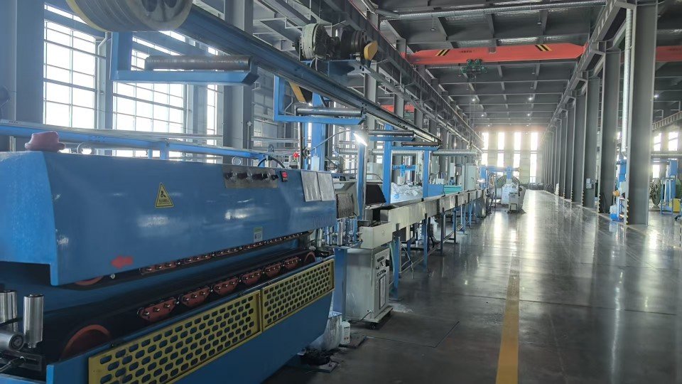
Manufacturing Capability
Why Source From Jinda Cable
Behind every drum we ship sits a 38-year track record, five production bases under one MES system, and a documentation discipline that gets cables through customs without delays.

-
Every cable tested twice before shipping
Since 1987, our two-stage QC has been refined to a science: routine test on the production line, then full electrical and mechanical re-test before packing. Across 50+ export markets, our return rate stays under 0.3%.
-
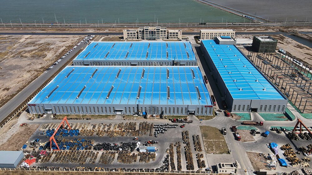
Five production bases, 470,000 m², synced via MES
Tianjin, Liaoning, Heilongjiang, Shandong, and Xian — each base runs under one unified MES system. Same recipe, same protocols, same traceability, regardless of which plant ships your order.
-
3,000+ SKUs, custom configurations welcome
Standard sizes ship from inventory. Special voltage grades, color-coding, drum lengths, or armor configurations are routine — submit your spec and our team will quote the lead time honestly.
-
Trusted by EPC contractors in 50+ countries
We supply utilities, mining operators, port authorities, and large industrial OEMs across Europe, the Americas, Southeast Asia, the Middle East, and Africa.
-
Full paperwork shipped with every order
Every shipment includes factory test report, certificate of origin (COO), packing list, and bill of lading (B/L). Customer-nominated witness testing can be arranged before shipment.
Our Track Record
98.7%
On-time shipment rate (last 24 months)
< 0.3%
Return rate across export markets
25 days
Typical sea freight Tianjin → Rotterdam
100%
Shipments with routine test report attached
Logistics & Delivery
Packaging, Shipping & Documentation
What we handle on our side from production floor to the port of loading. Product-specific installation guidance is supplied with the datasheet that accompanies each order.
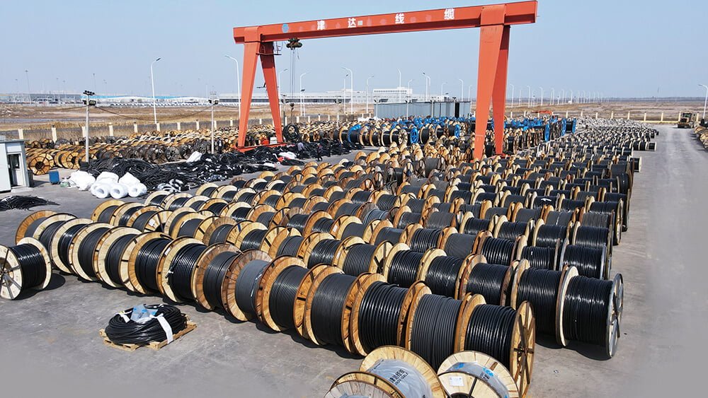
Packaging
- Wooden or steel drums per IEC 62004
- Coil packaging available for small cross-sections
- Standard drum lengths plus custom lengths on request
- Each drum labeled with type, voltage, cross-section, length, batch
- Waterproof wrapping for export shipments
- Cable ends sealed against moisture ingress
- Private-label / OEM packaging available under NDA
Shipping
- FCL / LCL sea freight, air freight on request
- Trade terms: EXW, FOB, CFR, CIF, DDP
- Ports of loading: Tianjin / Qingdao / Shanghai
- Typical sea freight to Rotterdam: 25 days
- Lead time confirmed at order acknowledgement
- Container loading photos sent before sailing
Documentation
- Factory routine test report (per applicable standard)
- Commercial invoice and packing list
- Certificate of origin (CO) — China Council, FORM A, FORM E available
- Bill of lading (B/L) — original or telex release
- Third-party inspection by SGS / BV / TÜV on request
- Customer-nominated witness testing arranged before shipment
Get in Touch
Request a Quote for
Shielded Control Cable
What You'll Receive
- Technical quotation with itemized FOB / CIF pricing
- Sample factory test report from a previous shipment
- Realistic lead time including raw-material procurement
- Direct contact with the assigned sales engineer


Email
info@jindacablegroup.comResponse Time
Within 1 business day
Related Products