/ 0.6/1kV
XLPE Steel Tape Armored Power Cable
Model: YJV22 / N2XBY
XLPE insulated steel tape armored power cable suitable for underground power distribution requiring additional mechanical protection.
- Voltage Rating
- 0.6/1kV
- Number of Cores
- Array
- Cross Section
- 1.5–630 mm²
- Conductor
- Copper Clad Aluminum
- Armoring
- Steel Tape Armored
- MOQ
- ≥ 100 m
Standards & Certifications
- GB/T
- GB/T 12706
- IEC
- IEC 60502
Downloads
Specifications
Technical Specifications & Performance
Construction
- Model / Series
- YJV22 / N2XBY
- Voltage Rating
- 0.6/1kV
- Conductor Material
- Copper Clad Aluminum
- Conductor Class
- Class 2 Stranded
- Cross Section
- 1.5–630 mm²
- Number of Cores
- Array
- Insulation
- XLPE
- Sheath
- PVC
- Armoring
- Steel Tape Armored
- MOQ
- ≥ 100 m
Performance
- Max. Conductor Temp.
- 90°C
- Min. Bending Radius
- 15 × Cable Outer Diameter
About This Product
The Most Widely Installed Armoured Cable in Underground Power Distribution
XLPE Steel Tape Armoured Power Cable (model designation YJV22 for the copper-conductor variant, YJLV22 for aluminium; internationally equivalent to N2XBY per the European VDE/IEC code for LV constructions, N2XSBY / NA2XSBY for MV constructions with copper screen; and BS 5467 for the LV UK-market cable) is the global standard for underground power distribution requiring mechanical protection. By volume shipped per year, it is the highest-tonnage armoured cable specification on the planet — more YJV22 / YJLV22 is installed globally in any given year than all other armoured cable types combined. The double-steel-tape construction provides reliable mechanical protection for direct-buried cable runs in soft-to-medium soil at a lower cost and weight than steel wire armoured cable (YJV32 / SWA).
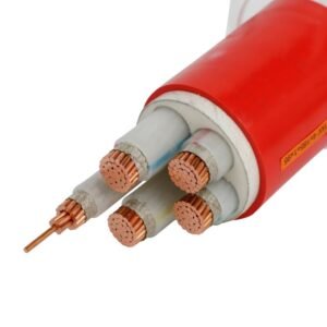
The defining armour element is the double galvanised steel tape applied helically over the PVC inner sheath with a minimum 15 percent overlap between successive tape wraps — the second tape layer is wound in the opposite direction to the first, producing a cross-helical double-tape structure that closes the gaps where any single-tape wrap leaves the inner sheath exposed at the gap between consecutive turns. The double-tape construction provides good compressive and lateral crush resistance adequate for direct burial in soft soil, cable trenches with sand bedding, and mechanical-impact environments. What it does not provide is meaningful tensile strength — the overlapping tape layers separate under longitudinal tension, making the steel tape construction the wrong specification for vertical shafts, submarine crossings, and sloped terrain where the cable hangs under its own weight.
Production follows IEC 60502-1 (LV) and IEC 60502-2 (MV) as primary international references, plus BS 5467 (UK 0.6/1 kV), BS 6622 and BS 7835 (UK MV), DIN VDE 0276-603 (German LV), DIN VDE 0276-620 (German MV), HD 603 S1 / HD 620 S1 (CENELEC harmonised), AS/NZS 5000.1 / AS/NZS 1429.1 (Australia/NZ), and SASO 1694 (Saudi Arabia and Gulf). Standard lead time is 18 to 35 days; container-load orders for utility-scale and infrastructure projects ship through Tianjin, Qingdao, and Shanghai ports.
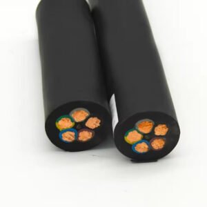
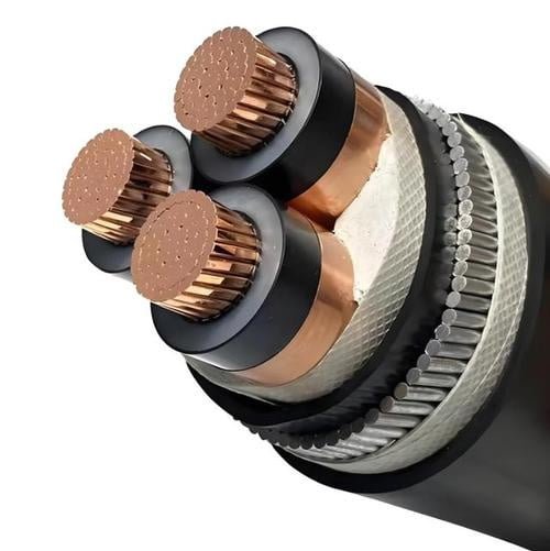
Cable Structure
Double Cross-Helical Steel Tape: Maximum Coverage, Minimum Weight
STA cable construction is lighter and simpler than SWA, using flat steel tape rather than round steel wires. The two tape layers wound in opposite directions at ≥15% overlap ensure 100% coverage of the inner sheath surface with no gaps, at a material cost well below that of the steel wire armour. The construction optimises for crush resistance (the tape area distributes compressive loads) rather than tensile strength (tapes separate under longitudinal pull). Understanding this distinction is the key to specifying STA vs SWA correctly.
-
1
Conductor — Class 2 Copper or Aluminium
Plain annealed copper per IEC 60228 Class 2 (YJV22) or hard-drawn aluminium Class 2 (YJLV22). Stranded compacted circular (CM) for 16 to 300 mm²; shaped sector (SM) for three-core 150 mm² and above. Solid Class 1 conductors available for small cross-sections (16 and 25 mm²) on request. Aluminium YJLV22 is the default choice for utility distribution network feeders where the conductor cost saving of 30-40 percent over copper outweighs the larger cross-section required for the same ampacity.
-
2
Insulation System — XLPE (LV) or Triple-Extruded XLPE (MV)
For LV 0.6/1 kV: single-layer XLPE insulation per IEC 60502-1, wall thickness 0.7 mm (1.5 mm²) to 2.8 mm (1000 mm²), rated 90°C continuous. For MV 3.6/6 kV and above: triple-extruded conductor screen + XLPE + insulation screen simultaneously in a single CV-cure production pass — the same process as unarmoured YJLV. Both configurations rated 90°C continuous, 130°C emergency, 250°C short-circuit (5 seconds). The 90°C XLPE rating gives 30-40 percent higher ampacity than 70°C PVC-insulated NYY at the same cross-section.
-
3
Metallic Screen (MV Only) — Copper Tape
For medium-voltage variants: helical copper tape screen over the insulation screen, sized to carry the project earth-fault current for the specified clearing time. This is a fault-current path for network protection operation, not an EMI screen. The copper screen cross-section must be specified at order based on the network’s fault-current level and protection clearing time. LV YJV22 has no metallic screen — the steel tape armour itself provides the earth-fault path at LV.
-
4
Inner Sheath — Extruded PVC Bedding
Insulated (and screened for MV) cores cabled together with polypropylene filler rods, bound with tape, then bedded with an extruded PVC inner sheath. The inner sheath provides a smooth cylindrical surface for the steel tape armour to wrap over, prevents the tape edges from cutting into the core insulation, and provides the bedding that distributes compressive loads from the steel tape to the cable core evenly. Wall thickness typically 0.8 to 1.4 mm depending on cable diameter.
-
5
Steel Tape Armour — Double Galvanised Steel Tape, Cross-Helical
Two layers of galvanised steel tape applied helically over the inner sheath, with the second layer wound in the opposite direction to the first, at a minimum 15 percent overlap per IEC 60502. Tape width typically 20-50 mm, thickness 0.2-0.5 mm depending on cable diameter, with longitudinal tension intentionally low — the tape wraps lie loosely enough to separate under longitudinal tension but tightly enough to prevent radial deformation under compressive load. The double cross-helical geometry ensures complete coverage of the inner sheath surface with no single-turn gaps. The galvanising (minimum zinc coating per IEC 60502) provides corrosion protection rated for 40+ years in buried service in most soil types without additional corrosion protection.
-
6
Outer Sheath — PVC Type ST2 (Black LV / Red MV) or LSZH
Extruded PVC outer sheath per IEC 60502 Type ST2 over the steel tape armour: black for LV 0.6/1 kV (universal LV power cable colour), red for MV cables (international MV identification colour). LSZH (low-smoke halogen-free) outer sheath available per BS 7835 or equivalent for tunnels, metro stations, and public buildings under fire-safety codes. Anti-termite and anti-rodent compounds available on quotation. Sheath wall thickness 1.2 to 2.3 mm depending on cable outer diameter per IEC 60502 specification.
Key Features
Cost-Effective Mechanical Protection for Standard Underground Distribution
STA cable is the dominant armoured cable choice worldwide because it delivers the mechanical protection that direct-burial underground power distribution actually needs — compressive crush resistance in stable soil, protection against accidental digging damage, and a low-resistance earth-fault path via the armour — at the lowest armoured-cable unit cost. The six features below are what IEC 60502 and BS 5467 collectively guarantee for the STA construction.
Direct Burial in Stable Soil Without Conduit
The double steel tape armour satisfies the mechanical-protection requirement for direct burial in stable, soft-to-medium soil per IEC 60364-5-52 and BS 7671. No concrete encasement or plastic conduit is required — just sand bedding, the cable, warning tape above, and backfill. Eliminating the conduit cost and installation complexity is the economic argument that makes STA the default choice for the majority of underground distribution projects: typical conduit costs 30-50 percent of cable cost, so the armour more than pays for itself.
10-20% Lower Cost Than SWA at the Same Rating
Steel tape uses less steel per metre than steel wire armour — the tape is thinner and the flat cross-section contains less material per unit coverage than a round wire construction. Combined with a faster armouring line speed for tape vs wire, the STA construction consistently costs 10-20 percent less per metre than SWA at the same cable specification. For utility-scale projects ordering tens of kilometres, this is real money. Over-specifying SWA where STA would do is one of the most common unnecessary cost escalations in underground distribution projects.
Lighter and Easier to Handle Than SWA
A 4-core 95 mm² YJV22 typically weighs 5 to 8 percent less per metre than the equivalent YJV32 — the round wire armour adds more steel mass. On large cable runs, the weight difference matters to drum handling, cable-pulling crew sizing, and cable-tray load calculations. The STA bending radius (12× OD during installation) is also tighter than SWA (15× OD), allowing installation through tighter cable duct bends and around closer cable tray corners.
90°C XLPE = 30-40% More Ampacity Than PVC-Armoured
The XLPE insulation inside the STA construction is rated 90°C continuous, 130°C emergency, and 250°C short-circuit (5 seconds) — exactly the same thermal rating as any other XLPE cable. Where older STA cables used PVC insulation (70°C limit), modern YJV22 / YJLV22 with XLPE delivers 30-40 percent higher ampacity at the same cross-section. For replacement of ageing PVC-insulated armoured cable (WAVECON, old NYY22), the XLPE upgrade allows the same physical cable size to carry significantly more current.
LV and MV in One Product Family
The same STA armour construction applies at 0.6/1 kV (IEC 60502-1, YJV22) and at 3.6/6 kV through 26/35 kV (IEC 60502-2, YJV22 with MV insulation). Projects spanning LV and MV distribution use a single product family with consistent construction, specification, and manufacturer documentation. For MV, the triple-extruded XLPE core with copper tape screen is identical to the unarmoured YJLV / N2XSBY — only the STA and outer sheath are added over the completed MV core.
Multi-Market Certified: IEC + BS + VDE + AS/NZS + SASO
Production certified to IEC 60502-1/2, plus BS 5467 (UK LV STA), BS 6622 and BS 7835 (UK MV STA, including LSZH), DIN VDE 0276-603/620 (Germany), HD 603 S1 / HD 620 S1 (CENELEC harmonised European), AS/NZS 5000.1 / AS/NZS 1429.1 (Australia/NZ), SASO 1694 (Saudi Arabia and Gulf). BASEC, KEMA, and SGS test reports available. For the UK construction market specifically, BS 5467 BASEC-certified STA cable is the standard acceptance reference for NICEIC, JIB, and Part P-approved installations.
How to Choose
Six Decisions Before You Place the Order
STA cable selection starts with the straightforward confirmation that steel tape is the right armour type for the installation — far less complex than SWA selection. The remaining decisions follow the same pattern as for any armoured XLPE power cable: voltage class, conductor material, core count, cross-section, and certification. Most underground distribution projects default to STA and only upgrade to SWA when a specific installation challenge demands the higher tensile strength. Walk through these six decisions before placing the order to avoid the most common specification errors.
Confirm STA is right (not SWA, not unarmoured)
Specify STA (YJV22) for: direct burial in soft to medium soil, cable trenches with sand bedding, cable duct and conduit installation requiring the armour as the earth-fault path, cable trays in mechanically harsh areas, and any installation without significant tensile loading. Upgrade to SWA (YJV32) for: vertical risers over 5-10 metres, submarine crossings, rocky soil, or overhead self-supporting spans. Downgrade to unarmoured (YJV/YJLV) for: indoor cable tray and conduit where no direct-burial or mechanical-impact risk exists. Using SWA where STA would do costs 10-20 percent more without benefit; using unarmoured cable where STA is required violates wiring codes.
Select LV (0.6/1 kV) or MV (3.6/6 kV through 26/35 kV)
LV 0.6/1 kV per IEC 60502-1 for all standard building services, industrial plant power distribution, and site distribution at 400V three-phase or 230V single-phase. MV per IEC 60502-2 for utility primary distribution, industrial primary supply, and renewable energy collector networks. For MV, specify the exact project voltage class (U₀/U) precisely — the insulation wall thickness and test voltage differ between classes (3.4 mm at 8.7/15 kV; 5.5 mm at 12/20 kV; 8.0 mm at 18/30 kV). Using the wrong voltage class is a safety failure, not just a specification error.
Copper YJV22 or aluminium YJLV22
Copper YJV22 for industrial plant power, commercial building services, and any application where higher ampacity per cross-section, compact physical size, or vibration tolerance (aluminium fatigues more easily) is important. Copper also simplifies termination. Aluminium YJLV22 for utility distribution network feeders, long cable runs at MV where the conductor-cost saving (30-40 percent lower than copper at equivalent ampacity) is meaningful at project scale. For replacement of older copper-conductor armoured cable, copper is the natural like-for-like choice; for new utility distribution projects, aluminium is the default.
Core count and cross-section
2-core for single-phase. 3-core for three-phase balanced load. 4-core (3+N or 3+E) for three-phase + neutral or three-phase + earth — the most common utility distribution configuration. 5-core (3+N+E) for three-phase + neutral + earth under TN-S earthing systems. 3+1 reduced-neutral (e.g., 3×95+1×50 mm²) for long utility feeders where neutral current is substantially lower than phase current. For cross-section sizing, use IEC 60364-5-52 (LV) or IEC 60287 (MV) with derating factors for installation method — STA cable has a small additional thermal resistance from the steel tape and outer sheath; apply a 3-5 percent derating on top of unarmoured ampacity tables.
Verify armour can carry the earth-fault current (LV)
For LV YJV22 installations where the steel tape armour is used as the circuit protective conductor (CPC) — the standard approach in most BS 7671 and IEC 60364 installations — verify that the armour’s cross-sectional area satisfies the earth-fault current and disconnection-time requirements per BS 7671 Table 54.7 or IEC 60364-5-54. For larger cable cross-sections with high prospective fault currents, the armour area is typically adequate; for smaller cables and long circuits with slow protection, a supplementary earth conductor inside the cable may be needed. Specify this at order time if relevant.
Target-market certification and fire performance
For most global markets, IEC 60502-1/2 certification covers the product. For UK projects, add BS 5467 (LV) or BS 6622 (MV) — and for UK tunnels and public buildings, add BS 7835 LSZH sheath. For Australian and NZ projects, AS/NZS 5000.1 / AS/NZS 1429.1 with RCM mark. For Middle East projects, SASO 1694. For German and Northern European projects, DIN VDE 0276-603 (LV) or DIN VDE 0276-620 (MV). For European CPR compliance, specify Eca (standard PVC sheath) or Dca / Cca (LSZH sheath or additional flame-retardant treatment) as required by the building classification.
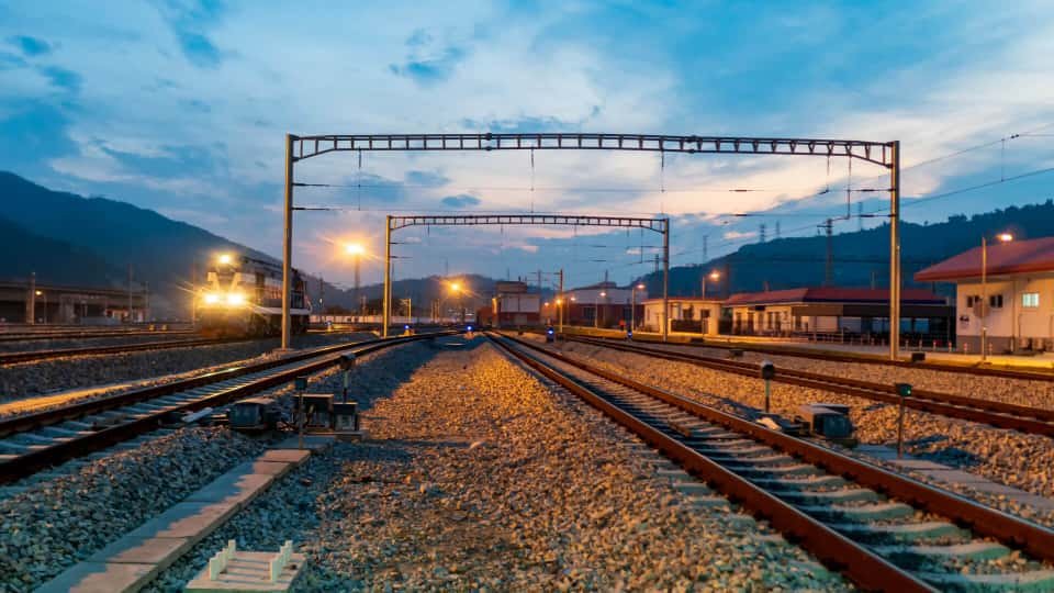
Applications
The Standard Underground Power Cable for Infrastructure and Industrial Projects
YJV22 / YJLV22 appears in essentially every underground power distribution infrastructure project globally: urban utility networks, industrial plant wiring, commercial and residential site distribution, and renewable energy plant electrical systems. The four scenarios below cover the highest-volume applications. The cross-section, core count, and voltage class vary by project; the STA construction is the common specification thread across all of them.
Urban & Suburban Underground Distribution
LV network feeders from substation to local transformer pillars and service cutouts, MV primary distribution from 11/22/33 kV substation to local distribution transformers, campus electrical supply between buildings at universities and industrial parks. Typically YJLV22 aluminium 4-core or 3+1 configuration at LV, YJLV22 three-core at MV, direct-buried in concrete-encased ducts or in open trenches with sand bedding. This is the single largest application category globally by cable metres shipped per year.

Industrial Plant Power Distribution
Factory main distribution board to motor control centres, outdoor plant cable trenches between buildings, cable routes through mechanical plant rooms where cables are exposed to physical damage, large pump and compressor feeder cables in water treatment and process plants, underground cables across yard areas at ports and logistics facilities. Typically copper YJV22 for the mechanical damage tolerance and earth-fault path. STA replaces cable trays in outdoor areas where cable duct work is impractical or expensive.
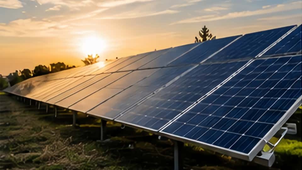
Renewable Energy Plant Distribution
Solar farm DC collection (DC STA cable), solar and wind farm AC collection between inverter stations and the substation (MV YJLV22 at 12/20 or 18/30 kV), storage facility power interconnects, geothermal plant electrical distribution. The flat terrain characteristic of most renewable energy plants makes STA the natural specification — no vertical risers or rocky ground to demand SWA. Typically YJLV22 aluminium three-core or single-core at MV for the large power flows involved.

Large Building & Infrastructure Services
Shopping centre and data centre main distribution from incoming substation to building distribution boards, hospital primary supply feeders (particularly through plant rooms), airport terminal power distribution, car park and external lighting distribution where cables are vulnerable to vehicle damage, underground cable routes in pedestrian areas and car parks. LV copper YJV22 4-core at 16-240 mm² covers the dominant building services feeder range. LSZH outer sheath specified for hospital and public building routes under modern fire codes.
Not appropriate for: Vertical risers or mine shafts (use SWA / YJV32 with tensile strength). Submarine crossings (use SWA or dedicated submarine cable). Rocky or stony direct burial where stone edges would puncture the tape (use SWA). Indoor cable tray installation without mechanical-damage risk (use unarmoured YJV / YJLV / N2XY to save cost). Continuous flexing (use rubber-insulated YCW or flexible cable). Mining underground mobile equipment (use MYJV / MYJV22 mining-specific cable). High voltages above 35 kV (use IEC 60840 HV cable). Single-core AC cable at medium voltage requiring armour: use aluminium wire armour (AWA) — never steel tape or steel wire on single-core AC cable, due to eddy current losses in the ferromagnetic steel.
Technical Data
YJV22 4-Core 0.6/1 kV Standard Sizes
Reference values for 4-core YJV22 (Cu/XLPE/PVC/STA/PVC, 0.6/1 kV) per IEC 60502-1. Ampacity per IEC 60364-5-52 installation method D (direct buried in soil, 20°C ground temperature, 1.0 K·m/W soil thermal resistivity, 90°C conductor temperature). Direct-buried ampacity is approximately 10-15 percent higher than free-air installation because the soil provides better thermal coupling than air. Apply the appropriate derating factors for grouped cable circuits and non-standard soil thermal resistivity. For MV YJV22 / YJLV22 at 3.6/6 kV through 26/35 kV, reference the YJLV medium-voltage data table for the base values and apply a 3-5 percent STA derating factor. Aluminium YJLV22 variant available at approximately 79 percent of copper ampacity at the same cross-section.
| Cores & Size | Conductor Construction | Approx. Cable OD | DC Resistance (per core) | Ampacity (buried, 90°C cond.) | Approx. Weight |
|---|---|---|---|---|---|
| 4×16 mm² | Compacted circular (CM) | ~ 25 mm | 1.15 Ω/km | 95 A | ~ 1,450 kg/km |
| 4×25 mm² | Compacted circular (CM) | ~ 28 mm | 0.727 Ω/km | 120 A | ~ 1,900 kg/km |
| 4×35 mm² | Compacted circular (CM) | ~ 30 mm | 0.524 Ω/km | 150 A | ~ 2,400 kg/km |
| 4×50 mm² | Sector compacted (SM) | ~ 33 mm | 0.387 Ω/km | 185 A | ~ 3,050 kg/km |
| 4×70 mm² | Sector compacted (SM) | ~ 37 mm | 0.268 Ω/km | 235 A | ~ 4,000 kg/km |
| 4×95 mm² | Sector compacted (SM) | ~ 41 mm | 0.193 Ω/km | 280 A | ~ 5,200 kg/km |
| 4×120 mm² | Sector compacted (SM) | ~ 45 mm | 0.153 Ω/km | 325 A | ~ 6,500 kg/km |
| 4×150 mm² | Sector compacted (SM) | ~ 49 mm | 0.124 Ω/km | 375 A | ~ 7,900 kg/km |
| 4×185 mm² | Sector compacted (SM) | ~ 54 mm | 0.0991 Ω/km | 430 A | ~ 9,700 kg/km |
| 4×240 mm² | Sector compacted (SM) | ~ 60 mm | 0.0754 Ω/km | 505 A | ~ 12,300 kg/km |
| 4×300 mm² | Sector compacted (SM) | ~ 66 mm | 0.0601 Ω/km | 580 A | ~ 15,200 kg/km |
| 3×95+1×50 mm² | SM | ~ 43 mm | 0.193 / 0.387 Ω/km | 288 A | ~ 5,900 kg/km |
| 3×120+1×70 mm² | SM | ~ 48 mm | 0.153 / 0.268 Ω/km | 335 A | ~ 7,500 kg/km |
| 3×150+1×70 mm² | SM | ~ 52 mm | 0.124 / 0.268 Ω/km | 385 A | ~ 9,000 kg/km |
| 3×185+1×95 mm² | SM | ~ 57 mm | 0.0991/ 0.193 Ω/km | 440 A | ~ 11,200 kg/km |
| 3×240+1×120 mm² | SM | ~ 64 mm | 0.0754/ 0.153 Ω/km | 525 A | ~ 14,400 kg/km |
DC resistance per IEC 60228 plain annealed copper Class 2, 20°C. Ampacity per IEC 60364-5-52 installation method D (single cable direct buried, 20°C ground, 1.0 K·m/W, 90°C conductor). For installation in air on cable tray (method E), ampacity is approximately 10-15 percent lower than buried. For grouped cables in the same trench, apply grouping derating factors per IEC 60287. The STA armour adds approximately 3-5 percent additional thermal resistance vs unarmoured YJV at the same core cross-section — apply this derating when using unarmoured cable ampacity tables as a base reference. Aluminium YJLV22 carries approximately 79 percent of copper YJV22 ampacity at the same cross-section, making YJLV22 at one cross-section step up the economic choice for most utility distribution applications.
Insulation voltage: 0.6/1 kV per IEC 60502-1 (this table); MV 3.6/6 kV through 26/35 kV per IEC 60502-2 on request. Operating temperature: 90°C continuous / 130°C emergency / 250°C short-circuit (5s). Minimum bending radius: 12× OD during installation (tighter than 15× OD for SWA). Outer sheath black (LV) or red (MV). Flame test: IEC 60332-1-2 standard; CPR Eca for standard PVC sheath; Dca or higher for LSZH sheath or flame-retardant treatment. Steel tape armour galvanised per IEC 60502; BS 1052 galvanised steel tape per BS 5467 for UK-market cable.
Comparison
STA vs SWA vs Unarmoured vs PVC-Armoured: Picking the Right Cable
Five closely-related underground power cables cover the overwhelming majority of the market. The selection logic is simple once you understand the key differentiators: armour type (none / STA / SWA), insulation material (PVC vs XLPE), and conductor material (copper vs aluminium). The table below shows the decisive parameters; the right choice for any project can be read off in one pass.
| Attribute | YJV22 (STA, this product) | YJV32 (SWA) | YJV (unarmoured) | YJLV22 (STA, aluminium) |
|---|---|---|---|---|
| Standard (LV) | IEC 60502-1 / BS 5467 | IEC 60502-1 / BS 5467 | IEC 60502-1 | IEC 60502-1 / BS 5467 |
| Standard (MV) | IEC 60502-2 / BS 6622 | IEC 60502-2 / BS 6622 | IEC 60502-2 | IEC 60502-2 / BS 6622 |
| Armour type | Double galv. steel tape | Single-layer helical steel wire | None | Double galv. steel tape |
| Conductor material | Copper | Copper | Copper or aluminium | Aluminium |
| Insulation | XLPE (90°C) | XLPE (90°C) | XLPE (90°C) | XLPE (90°C) |
| Tensile strength | Low (tapes separate) | High (wires hang in shafts) | None | Low |
| Crush resistance | Good (tape area) | Very good (wire geometry) | None | Good |
| Direct burial (soft soil) | Yes | Yes | Requires conduit | Yes |
| Direct burial (rocky soil) | Marginal | Yes | No | Marginal |
| Vertical riser > 10 m | Not recommended | Yes | No | Not recommended |
| Min. bending radius | 12× OD | 15× OD | varies | 12× OD |
| Cost (relative to YJV22) | 1.00 (baseline) | 1.10 to 1.20 (more steel) | 0.75 to 0.85 (no armour) | 0.65 to 0.75 (Al conductor) |
When to choose YJV22 (this product)
The default choice for the vast majority of underground power distribution projects: direct burial in stable soil, cable trenches, cable ducts, industrial plant cable runs in mechanically harsh areas, building services feeders through at-risk locations. Copper conductor YJV22 for industrial and building services; aluminium YJLV22 for utility distribution feeders. The STA construction eliminates conduit cost for buried runs while costing 10-20 percent less than SWA at the same specification.
When to choose an alternative
For vertical shafts, submarine crossings, rocky soil, or overhead spans with tensile loading, step up to SWA / YJV32. For indoor cable tray and conduit installation without mechanical impact risk, save 15-25 percent with unarmoured YJV / YJLV. For utility distribution where conductor cost is dominant, specify aluminium YJLV22 (30-40 percent cheaper at equivalent ampacity). For fire-sensitive installations in tunnels or public buildings, specify the LSZH outer sheath variant per BS 7835. For high voltages above 35 kV, use IEC 60840 HV cable. For single-core AC circuits needing armour, use aluminium wire armour (AWA) — never steel tape on single-core AC cable.
Frequently Asked Questions
Common Questions From Electrical Engineers, Contractors, and Project Buyers
Why is the bending radius of YJV22 tighter than YJV32?
Steel tape bends more easily than the equivalent round wire armour because the tape can shift circumferentially as the cable bends — the inner tape edge compresses and the outer edge extends, accommodating the bend without fracturing. The minimum bending radius per IEC 60502 is 12× OD for STA (YJV22) vs 15× OD for SWA (YJV32), giving STA a meaningfully tighter radius. In practice, the tighter bending radius allows STA cable to navigate through duct bends and into cable duct boxes that SWA cable would not fit. For conduit and duct installations with space constraints, STA’s tighter bending radius is a genuine installation advantage over SWA.
Can the steel tape armour be used as the circuit earth?
Yes — using the steel tape armour as the circuit protective conductor (CPC) is standard practice in most IEC 60364 and BS 7671 installations with YJV22 STA cable. The armour provides a low-resistance metallic path between the cable terminations and satisfies the requirements for a protective conductor provided the armour cross-section is adequate for the circuit’s prospective earth-fault current and disconnection time. Per BS 7671 Table 54.7 and IEC 60364-5-54, the armour cross-section must be at least equal to the minimum protective conductor cross-section for the circuit’s phase conductor size. For large-cross-section cables, the armour is almost always adequate; for smaller cables (< 25 mm²) with slow protection, verify the calculation. A separate supplementary earth inside the cable can be specified if the armour calculation fails.
Is YJV22 the same as BS 5467 cable?
Functionally equivalent at the construction level. YJV22 per IEC 60502-1 and BS 5467 Cu/XLPE/STA/PVC at 0.6/1 kV both describe copper-conductor, XLPE-insulated, double-steel-tape-armoured, PVC-sheathed power cable. The two standards are harmonised with near-identical dimensional and electrical specifications. Most production runs satisfy both certifications simultaneously. Specify both IEC 60502-1 and BS 5467 at order for projects requiring dual acceptance by different authorities. For the UK market specifically, BASEC-certified BS 5467 cable is the standard contractual acceptance reference for electrical installation contractors and distribution network operators (DNOs).
What burial depth is required for YJV22 without additional protection?
National wiring codes specify minimum cover depths: typically 600 mm in areas without vehicular traffic, 900 mm under roads with vehicular traffic, and 450 mm in areas with only pedestrian traffic per BS 7671 Table 52.2. Warning tape at 100-150 mm above the cable during backfill is good practice. For additional protection against excavator damage in high-risk areas (main roads, areas with frequent ground disturbance), concrete tiles or split plastic conduit above the cable provides an additional warning layer. No conduit is required for the cable itself — the STA construction satisfies the mechanical protection requirement for direct burial at the specified depths. In soft-rock or mixed soil, a 100 mm sand bedding layer below the cable prevents puncture from angular stones or compaction-induced loads.
Why should I choose XLPE (YJV22) over PVC-insulated armoured cable?
Three decisive reasons. Ampacity: XLPE-insulated YJV22 operates at 90°C conductor temperature vs 70°C for PVC-insulated cable, delivering 30-40 percent higher sustained ampacity at the same cross-section. For a new installation, this means specifying a smaller cross-section XLPE cable for the same load, saving conductor cost and installation weight. Short-circuit capacity: XLPE withstands 250°C for 5 seconds vs 160°C for PVC — XLPE tolerates more severe fault events without insulation damage. Service life: XLPE doesn’t plasticise and lose mechanical properties at high temperatures the way PVC does; XLPE-insulated cables typically last 40-50 years in buried service vs 25-35 years for PVC-insulated. The cost premium for XLPE over PVC insulation is typically only 5-10 percent — it is almost always the better value for any new installation.
What is the typical lead time and MOQ?
LV YJV22 in common cross-sections (4-core 25-240 mm²) typically ships in 18–30 days from order — these run on continuous XLPE extrusion and steel-tape armouring lines with stable raw material inventory. MV YJV22 / YJLV22 at 3.6/6 kV and above takes 28-45 days due to the slower triple-extrusion + CV-cure MV core production before the armouring pass. LSZH outer sheath variant adds 5-7 days. Multi-market certification (IEC + BS + VDE) adds 3-5 days for documentation and witness testing. MOQ is 1,000 m for LV and 500 m for MV per cross-section and core-count combination. For utility-scale and infrastructure projects ordering 20 km+, dedicated production runs deliver the best unit pricing and quality consistency — container-load shipments through Tianjin, Qingdao, or Shanghai ports.
Installation & Handling Tips
Six Practices for STA Cable That Maximise Service Life and Safety
STA cable installation is more straightforward than SWA — the tape construction terminates more simply than wire armour, and the tighter bending radius makes routing easier. But several specific practices consistently determine whether the armour does its protective job for the full 40-year service life, or whether installation shortcuts create the failure modes the armour was intended to prevent.
Use proper STA cable glands at every termination
STA cable requires armour cable glands (not standard PVC glands) that grip the steel tape layer and provide both a mechanical strain relief and an earth-bonding connection. The gland must make 360-degree contact with the steel tape layer to provide a low-resistance earth path — pigtail connections from individual tape strips to a lug have high contact resistance and poor mechanical retention. Specify the gland size for the cable OD (STA cable is slightly smaller OD than SWA at the same cross-section) and the material (brass standard; stainless for corrosive environments).
Prepare the trench correctly before cable laying
For direct-burial applications, the trench preparation determines whether the cable survives ground movement and compaction over decades. Minimum 100 mm sand or fine-soil bedding below the cable; minimum 150-300 mm sand or fine-soil above before backfilling with native soil. Remove any large stones, glass, or other angular material from the cable zone — STA provides good protection against distributed compressive loads but can be punctured by a single angular stone edge at concentrated point load. Warning tape or concrete tiles at 100-150 mm above the cable depth; cable route marker posts at changes of direction.
Maintain 12× OD minimum bending radius
STA cable minimum bending radius is 12× OD per IEC 60502 (smaller than the 15× OD of SWA, because the tape construction bends more readily than round wire). Bending tighter than 12× OD permanently kinks the steel tape layers and splits the tape edge, leaving a crack in the armour that provides no mechanical protection at that point and a potential corrosion initiation site. The kink is invisible from outside but creates a failure location under concentrated compressive load. The tighter STA bending radius (vs SWA) allows routing through tighter duct bends and into junction boxes where SWA would not fit.
Lay in a snake (S-curve) to allow thermal expansion
Cable expands and contracts with temperature — particularly significant for XLPE cable which operates over a wide temperature range from cold ground (−5°C) to full load (90°C conductor). Laying the cable in a gentle S-curve (snaking) allows 2-3 percent excess cable length in the trench to accommodate thermal movement without pulling the cable straight and tensioning the terminations. For straight-run cable in conduit, leave a small service loop at each joint box. Pulling the cable perfectly straight and tight at ambient temperature means it will be under tension at operating temperature, potentially pulling conductor lugs out of terminations.
Megger test before energising
Insulation resistance test (megger) at 1 kV DC between every conductor and earth (armour), and between adjacent conductors, before energising any buried cable installation. Expected reading for new LV YJV22 is > 1000 MΩ per km; readings below 100 MΩ indicate water ingress, insulation damage, or a termination fault — investigate and repair before applying mains voltage. Document the test results in the project handover. For MV installations, conduct both megger testing and partial-discharge testing as described in the YJLV medium-voltage cable product page.
Cap cable ends immediately after cutting
The steel tape armour is not watertight — moisture enters easily through the inter-tape gaps. Apply heat-shrink end caps or self-amalgamating tape to cable ends immediately after cutting, before moving the cut cable to the installation location. For cable lengths in open trenches awaiting connection, seal both ends before any rain event. For cable pulled into conduit or duct before final termination, seal the exposed end at the duct entry point. Moisture wicking into the cable during the construction period sits inside for years and slowly degrades the XLPE insulation, reducing insulation resistance and ultimately causing premature breakdown.
Safety note: Underground armoured cable installation must comply with the applicable national wiring code (BS 7671 in the UK, IEC 60364 internationally, AS/NZS 3000 in Australia/NZ). The steel tape armour must be earthed at all terminations per the wiring code — an unearthed armour is a safety hazard and a code violation. For LV installations using the armour as the CPC, verify the armour cross-section satisfies BS 7671 Table 54.7 or IEC 60364-5-54 for the circuit’s prospective earth-fault current. Use cable detection equipment before any excavation near existing buried cables. For MV installations, refer to the medium-voltage product page safety notes in addition to these STA-specific practices.
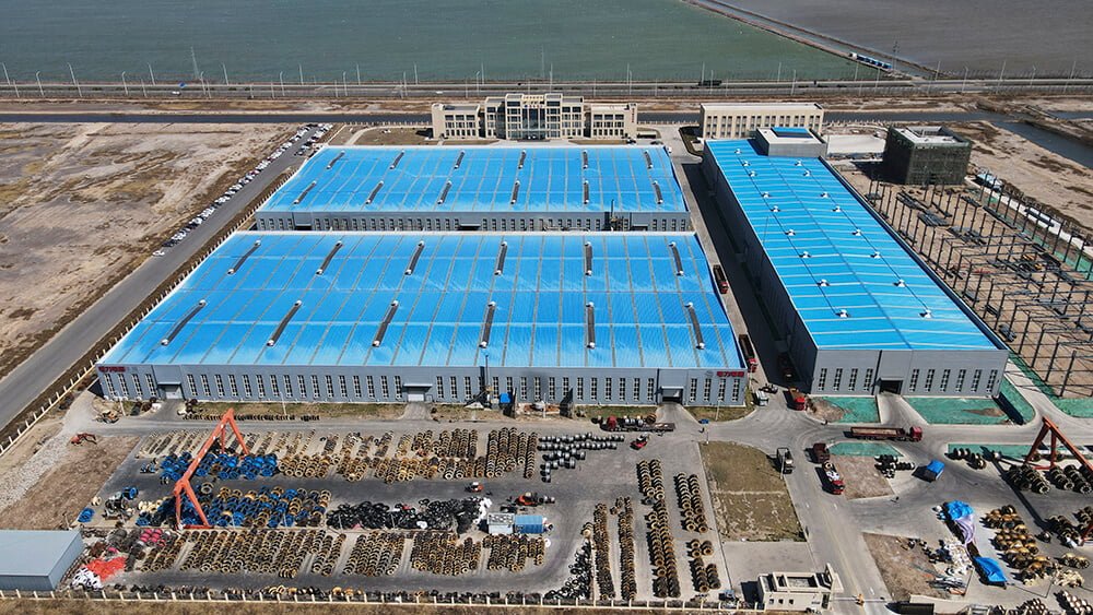
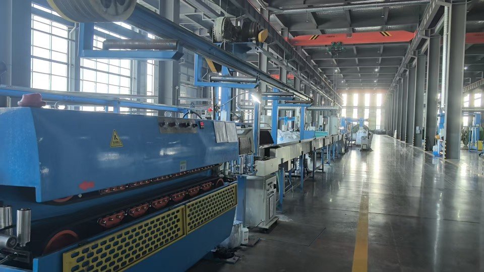
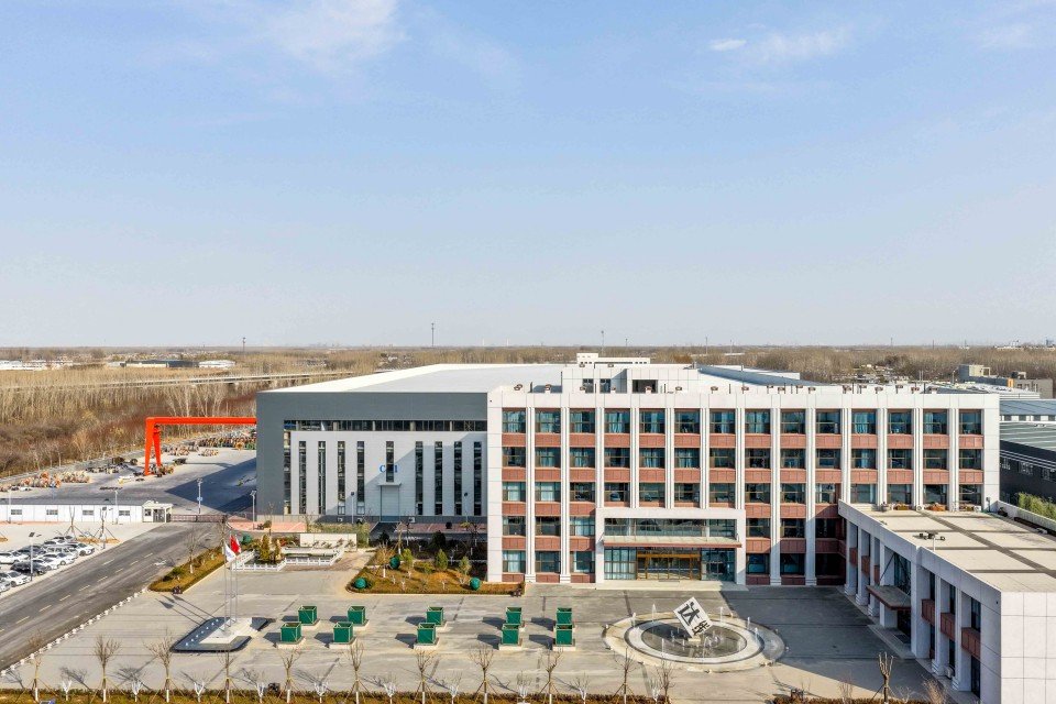
Manufacturing Capability
Why Source From Jinda Cable
Behind every drum we ship sits a 38-year track record, five production bases under one MES system, and a documentation discipline that gets cables through customs without delays.
-
Every cable tested twice before shipping
Since 1987, our two-stage QC has been refined to a science: routine test on the production line, then full electrical and mechanical re-test before packing. Across 50+ export markets, our return rate stays under 0.3%.
-
Five production bases, 470,000 m², synced via MES
Tianjin, Liaoning, Heilongjiang, Shandong, and Xian — each base runs under one unified MES system. Same recipe, same protocols, same traceability, regardless of which plant ships your order.
-
3,000+ SKUs, custom configurations welcome
Standard sizes ship from inventory. Special voltage grades, color-coding, drum lengths, or armor configurations are routine — submit your spec and our team will quote the lead time honestly.
-
Trusted by EPC contractors in 50+ countries
We supply utilities, mining operators, port authorities, and large industrial OEMs across Europe, the Americas, Southeast Asia, the Middle East, and Africa.
-
Full paperwork shipped with every order
Every shipment includes factory test report, certificate of origin (COO), packing list, and bill of lading (B/L). Customer-nominated witness testing can be arranged before shipment.
Our Track Record
98.7%
On-time shipment rate (last 24 months)
< 0.3%
Return rate across export markets
25 days
Typical sea freight Tianjin → Rotterdam
100%
Shipments with routine test report attached
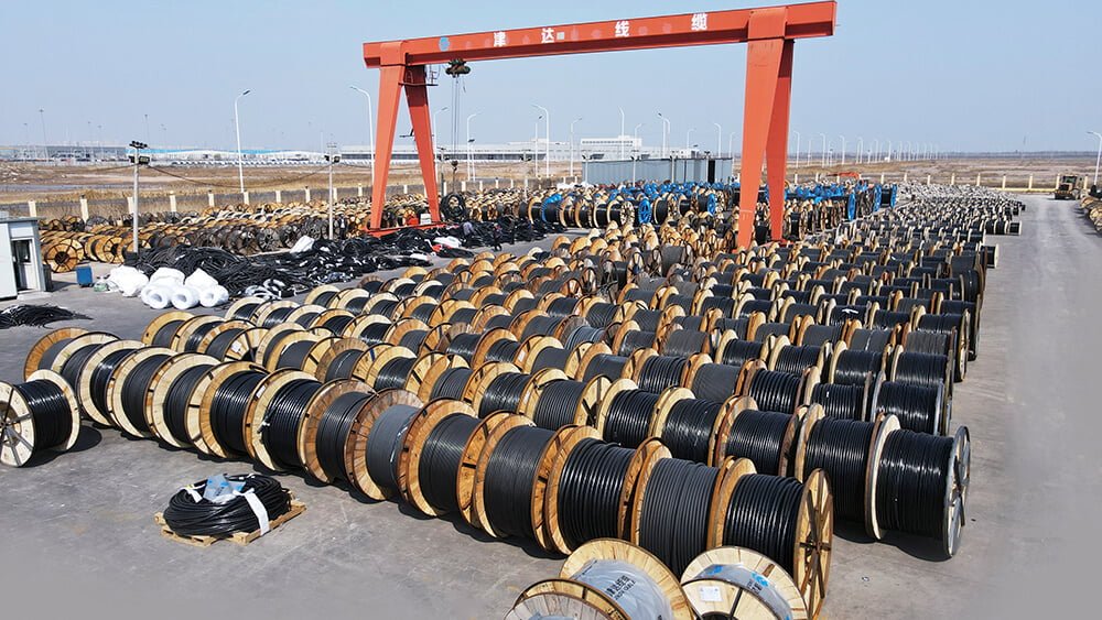
Logistics & Delivery
Packaging, Shipping & Documentation
What we handle on our side from production floor to the port of loading. Product-specific installation guidance is supplied with the datasheet that accompanies each order.
Packaging
- Wooden or steel drums per IEC 62004
- Coil packaging available for small cross-sections
- Standard drum lengths plus custom lengths on request
- Each drum labeled with type, voltage, cross-section, length, batch
- Waterproof wrapping for export shipments
- Cable ends sealed against moisture ingress
- Private-label / OEM packaging available under NDA
Shipping
- FCL / LCL sea freight, air freight on request
- Trade terms: EXW, FOB, CFR, CIF, DDP
- Ports of loading: Tianjin / Qingdao / Shanghai
- Typical sea freight to Rotterdam: 25 days
- Lead time confirmed at order acknowledgement
- Container loading photos sent before sailing
Documentation
- Factory routine test report (per applicable standard)
- Commercial invoice and packing list
- Certificate of origin (CO) — China Council, FORM A, FORM E available
- Bill of lading (B/L) — original or telex release
- Third-party inspection by SGS / BV / TÜV on request
- Customer-nominated witness testing arranged before shipment
Get in Touch
Request a Quote for
XLPE Steel Tape Armored Power Cable
What You'll Receive
- Technical quotation with itemized FOB / CIF pricing
- Sample factory test report from a previous shipment
- Realistic lead time including raw-material procurement
- Direct contact with the assigned sales engineer


Email
info@jindacablegroup.comResponse Time
Within 1 business day
Related Products