/ 0.6/1kV
XLPE Steel Wire Armored Power Cable
Model: YJV32 / SWA XLPE Cable
XLPE insulated steel wire armored power cable designed for heavy-duty power transmission in harsh installation environments.
- Voltage Rating
- 0.6/1kV
- Number of Cores
- Array
- Cross Section
- 10–630 mm²
- Conductor
- Copper Clad Aluminum
- Armoring
- Steel Wire Armored
- MOQ
- ≥ 100 m
Standards & Certifications
- GB/T
- GB/T 12706
- IEC
- IEC 60502
Downloads
Specifications
Technical Specifications & Performance
Construction
- Model / Series
- YJV32 / SWA XLPE Cable
- Voltage Rating
- 0.6/1kV
- Conductor Material
- Copper Clad Aluminum
- Conductor Class
- Class 2 Stranded
- Cross Section
- 10–630 mm²
- Number of Cores
- Array
- Insulation
- XLPE
- Sheath
- PVC
- Armoring
- Steel Wire Armored
- MOQ
- ≥ 100 m
Performance
- Max. Conductor Temp.
- 90°C
- Min. Bending Radius
- 15 × Cable Outer Diameter
About This Product
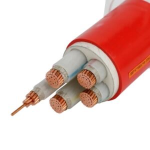
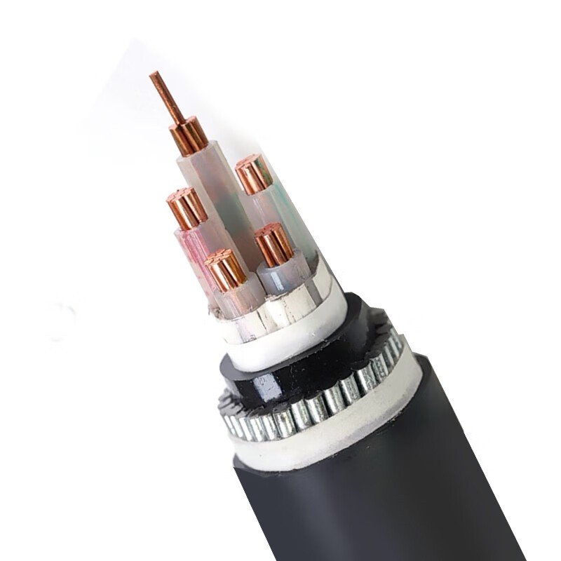
When Steel Tape Armour Is Not Enough: The SWA Solution
XLPE Steel Wire Armoured Power Cable (model designation YJV32 for the copper-conductor variant, YJLV32 for aluminium conductor; internationally equivalent to N2XSERY / NA2XSERY per the European VDE/IEC code for medium-voltage constructions, and BS 5467 for the low-voltage UK-market cable) is the highest-mechanical-protection tier of the XLPE power cable family. Where steel tape armoured (STA) cable — designated YJV22 / YJLV22 — is adequate for direct burial in stable, soft soil with compressive loads only, steel wire armoured (SWA) cable is specified when the installation imposes tensile forces, twisting, or repeated mechanical flexing on the cable: vertical risers in mine shafts, submarine crossings, rocky or stony direct burial, overhead self-supporting spans, and sloped terrain installations.
The defining structural feature is the layer of helically-applied galvanised steel wires (G1A grade per IEC 60502, wire diameter typically 0.8 to 2.5 mm depending on cable outer diameter) that replaces the two-layer overlapping steel tape of the STA construction. A single layer of round steel wires wrapped helically over the inner sheath provides both compressive and tensile strength — the wire construction resists pulling-out, can hang under its own weight in vertical shafts up to several hundred metres, and tolerates the twisting forces that would delaminate steel tape. The XLPE insulation underneath provides the same 90°C continuous / 250°C short-circuit thermal performance as all XLPE power cable; the SWA construction is an armour upgrade, not an insulation upgrade.
The cable is available at both low voltage (0.6/1 kV per IEC 60502-1) and medium voltage (3.6/6 kV through 26/35 kV per IEC 60502-2) with the same SWA construction. At medium voltage, the triple-extruded semi-conducting screen layers and copper tape metallic screen are added inside the armour in the same position as for the unarmoured YJLV / NA2XSY. Production follows IEC 60502-1 and IEC 60502-2 as primary references, plus BS 5467 (UK 0.6/1 kV), BS 6622 (UK MV SWA), DIN VDE 0276-620 (Germany), and AS/NZS 5000.1 / AS/NZS 1429.1 (Australia/NZ). Standard lead time is 20 to 40 days; supplied on heavy-duty wooden drums sized for the cable weight.
Cable Structure
Steel Wire Armour: What Makes It Different From Steel Tape
Both SWA and STA cables use steel for mechanical protection, but the wire construction and tape construction have fundamentally different strength profiles. Steel tape (STA, suffix 22) provides good compressive and lateral crush resistance but poor tensile strength — the overlapping tape layers open under longitudinal tension and provide little protection against twisting. Steel wire (SWA, suffix 32) provides high tensile strength, crush resistance, and tolerance for twisting forces. The choice between 22 and 32 comes down to whether the installation includes significant tensile or torsional loading on the cable.
-
1
Conductor — Class 2 Copper or Aluminium
Plain annealed copper per IEC 60228 Class 2 (YJV32) or hard-drawn aluminium Class 2 (YJLV32). Stranded and compacted circular (CM) for 16 to 300 mm²; shaped sector conductors (SM) for three-core 150 mm² and above to reduce cable overall diameter. Compact stranding eliminates interstrand air gaps that would otherwise concentrate voltage stress at the conductor screen interface.
-
2
Insulation System — XLPE with Semi-Conducting Screens (MV) or Plain XLPE (LV)
For LV 0.6/1 kV: single extruded XLPE layer, no semi-conducting screens required. Insulation wall 0.7 mm (1.5 mm²) to 2.8 mm (1000 mm²) per IEC 60502-1. For MV 3.6/6 kV and above: triple-extruded conductor screen + XLPE + insulation screen in a single production pass per the same process as the unarmoured YJLV — the SWA construction is applied on top of the completed triple-extruded core. Both configurations rated 90°C continuous, 130°C emergency, 250°C short-circuit for 5 seconds.
-
3
Metallic Screen (MV Only) — Copper Tape
For medium-voltage variants: helical copper tape screen sized to carry the project earth-fault current for the specified clearing time, applied over the insulation screen. Same function as in the unarmoured YJLV — a fault-current path, not an EMI screen. For LV YJV32, there is no metallic screen because the lower voltage class doesn’t require the electric-field management function that the screen provides in MV construction.
-
4
Inner Sheath — Extruded PVC Bedding
For multi-core cables, the insulated and screened cores are cabled together with polypropylene filler rods, bound with a tape, and then an extruded PVC bedding layer is applied over the assembly. The PVC inner sheath provides a smooth cylindrical surface for the steel wire armour to wrap over, prevents the steel wires from biting into the core insulation, and provides the compressive bedding that allows the wire armour to tighten uniformly under tensile load without damaging the cable core.
-
5
Steel Wire Armour — Helical Galvanised Steel Wires (G1A)
Single layer of galvanised round steel wires (G1A grade, minimum zinc coating per IEC 60502) applied helically over the inner sheath. Wire diameter selected to match the cable’s outer diameter for uniform coverage: 0.8 mm wires for smaller cables (OD 12-20 mm), 1.25 mm for medium cables (OD 20-35 mm), 1.6 mm for larger cables (OD 35-55 mm), 2.0 or 2.5 mm for the largest cables (OD 55+ mm). The wire lay angle is precisely calculated so the wire layer provides both longitudinal tensile strength (carrying the cable’s hanging weight in vertical shafts) and radial crush resistance. The galvanising provides corrosion protection in buried and underwater environments with indefinite buried life in most soil types without additional corrosion protection.
-
6
Outer Sheath — PVC Type ST2 (Black LV / Red MV) or LSZH
Extruded PVC outer sheath per IEC 60502 Type ST2 over the steel wire armour: black for LV 0.6/1 kV cables (the standard LV power cable colour), red for MV cables (the international MV identification colour, same convention as unarmoured YJLV). LSZH (low-smoke halogen-free) outer sheath available per BS 5467 or BS 7835 for installations in tunnels, metro stations, or public buildings under fire-safety codes. Anti-termite and anti-rodent PVC compounds available on quotation for tropical and rural installations.
Key Features
Why Steel Wire, Not Steel Tape: The Features That Matter
Both SWA and STA cables look similar in cross-section drawings, but their mechanical performance profiles are completely different. These six features explain when and why the steel wire construction is the required specification — and why substituting STA cable in an SWA-specified installation is an engineering error, not a cost optimisation.
High Tensile Strength for Vertical Installations
The helical wire construction provides the cable with significant tensile strength — the armour wires carry the cable’s weight load in vertical shafts, mine risers, and suspended spans. Typical safe working loads are 15 to 30 percent of the cable’s calculated breaking load. For a 4-core 95 mm² YJV32, the armour can support a hanging length of 300 to 500 metres under the cable’s own weight before reaching safe working load limits. Steel tape armour (YJV22) provides essentially no tensile strength — the tape layers separate under longitudinal tension within the first few metres of vertical drop.
Crush Resistance ≥ 1200 N/cm for Buried Use
The wire layer provides radial compressive strength comparable to double steel tape armour — typically 1200 N/cm or higher in the IEC 60502 crush test. For direct burial in rocky or stony soil, the round wire geometry distributes point loads across multiple wires simultaneously, preventing the localised deformation that flat tape armour suffers when a sharp stone edge contacts it. Suitable for direct burial without the concrete-duct protection that steel tape armour often requires in rocky ground.
Twisting Tolerance for Offshore and Marine Use
Helical wire armour tolerates rotational forces that would buckle or delaminate steel tape. Critical for submarine cables laid from cable barges (which introduce twisting during deployment), for cable risers on floating platforms that rotate with wave and wind loading, and for any installation where the cable runs over a sheave or drum during installation or operation. The wire-against-wire contact in the armour layer allows limited inter-wire movement that accommodates torsional forces without structural failure.
LV and MV in the Same Construction Family
The same SWA construction applies at both 0.6/1 kV (IEC 60502-1) and 3.6/6 kV through 26/35 kV (IEC 60502-2). For LV projects with SWA in the specification, supply YJV32 / YJLV32 at 0.6/1 kV rated under BS 5467 or IEC 60502-1. For MV projects, the same designation extends to the voltage class; the triple-extruded XLPE core and copper screen are added internally while the external SWA construction remains the same. This allows projects that span LV and MV distribution to use a single cable family with consistent specification and manufacturer documentation.
Earthing Path via Armour Connection
The galvanised steel wire armour provides a low-resistance earth continuity conductor when bonded to earth at cable terminations. For LV installations, the steel wire armour is typically used as the circuit earth, eliminating the need for a separate earth conductor in many installations. Per BS 7671 and IEC 60364, the armour cross-sectional area must be verified against the circuit’s prospective earth-fault current and disconnection time — for large cable cross-sections, the armour earth path is often adequate; for smaller cables, a supplementary earth conductor may be required.
IEC + BS + VDE + AS/NZS Multi-Market Certified
Production certified to IEC 60502-1 (LV) and IEC 60502-2 (MV) as primary international references, plus BS 5467 (UK LV SWA), BS 6622 (UK MV SWA), DIN VDE 0276-620 (Germany), AS/NZS 5000.1 (Australia/NZ LV), and AS/NZS 1429.1 (Australia/NZ MV). BASEC, KEMA, and SGS test reports available for project acceptance. Dual or triple certification on a single production run is standard practice for projects exporting across multiple regulatory regimes.
How to Choose
Six Decisions Before You Place the Order
SWA cable selection begins with confirming that steel wire rather than steel tape is actually required — the cost premium over STA is real, and over-specifying SWA where STA would work wastes project budget. Once the SWA construction is confirmed, the remaining decisions are the same as for any XLPE power cable: voltage class, conductor material, core count, cross-section, and certification. Walk through these six decisions before placing the order.
Confirm SWA is needed over STA
Specify SWA (32) when the installation includes: vertical or near-vertical runs of more than 5-10 metres where the cable hangs under its own weight; submarine or underwater crossing where the cable is laid from a barge and subject to twisting; direct burial in rocky, stony, or contaminated soil where flat tape would be punctured by sharp stones; overhead self-supporting spans; or any project specification that explicitly calls for “steel wire armoured” or “SWA.” For horizontal direct burial in stable, soft soil with no tensile risk, STA (22) is lighter, easier to terminate, and 10-20 percent cheaper.
Select LV (0.6/1 kV) or MV (3.6/6 kV through 26/35 kV)
LV 0.6/1 kV per IEC 60502-1 for distribution feeders, plant power circuits, building services main cables, and any circuit at 400V three-phase or 230V single-phase. MV 3.6/6 kV through 26/35 kV per IEC 60502-2 for utility primary distribution feeders, industrial primary supply, wind and solar farm collector cables. For MV, confirm the exact project voltage class (U₀/U) rather than specifying a nominal voltage — the insulation wall thickness differs between voltage classes and the cables are not interchangeable.
Copper YJV32 or aluminium YJLV32
Copper YJV32 for industrial plant power, building services, and applications where higher ampacity per cross-section is needed or where aluminium termination adds unacceptable complexity. Aluminium YJLV32 for utility MV distribution feeders and long cable runs where the 30-40 percent conductor-cost saving is significant at project scale. Aluminium SWA cables require aluminium-rated lugs and antioxidant compound at terminations — verify these are included in the project material list.
Core count and cross-section
Core count: 2-core for single-phase, 3-core or 3+E (3+1) for three-phase without separate earth or with reduced neutral, 4-core for three-phase + neutral or three-phase + earth, 5-core for three-phase + neutral + earth. For MV, 3-core is standard; single-core used for large cross-sections above 400 mm². Cross-section: size for ampacity per IEC 60364-5-52 (LV) or IEC 60287 (MV) with appropriate derating for installation method. SWA cable has slightly lower ampacity than unarmoured equivalent due to the additional thermal resistance of the armour and outer sheath — typically 3-5 percent lower; apply this derating when sizing.
Confirm maximum allowable pulling tension
For vertical or high-tension installations, calculate the cable’s maximum installed weight (total length × cable weight per metre), compare it to the armour’s rated safe working load (typically 30 to 50 percent of the catalogue breaking load for sustained hanging loads), and confirm the installation is within the safe envelope. For very long vertical runs (mine shafts deeper than 300-500 m), mid-span grip clamps or cleats must be designed to support the cable weight at intermediate levels. Specify the installation details at order so the armour wire diameter can be confirmed against the tensile requirement.
Target-market certification and fire performance
For most global markets, IEC 60502-1/2 certification covers the product. For UK projects, add BS 5467 (LV SWA) or BS 6622 (MV SWA). For Australian and NZ projects, AS/NZS 5000.1 (LV) or AS/NZS 1429.1 (MV) with RCM mark. For tunnel, metro, and public-building installations, specify LSZH outer sheath per BS 5467 LSZH variant or equivalent. The LSZH sheath adds 5-10 percent to cable unit price; verify whether it’s required by the project fire-safety specification before ordering.
Applications
Where Tensile Strength and Mechanical Toughness Are Non-Negotiable
SWA cable is specified whenever the installation environment imposes tensile, torsional, or point-impact loads that steel tape armour cannot handle reliably. The four scenarios below cover the dominant SWA applications globally — each one would be a failure risk with STA cable, and each one requires SWA to achieve the intended service life safely. Within each scenario, the cross-section, core count, and voltage class vary by project; the SWA construction is the common thread.
Mine Shaft & Vertical Riser Cables
Power supply down mine shafts, in vertical cable risers in tall industrial structures, and in deep boreholes. Typically copper YJV32 3-core or 4-core 35-185 mm² at 0.6/1 kV or 8.7/15 kV, with the armour providing the structural tensile load-carrying function. Cable cleats or grip clamps at intermediate levels for shaft depths exceeding the cable’s safe hanging weight. SWA is mandatory for any mine shaft power cable under most mining safety codes worldwide.
Submarine & River Crossings
River crossings, harbour crossing cables, short submarine links between islands or mainland and offshore platforms, and inter-dock power distribution along dock edges. Typically YJLV32 or YJV32 3-core 95-300 mm² at 8.7/15 kV or 18/30 kV. The armour provides mechanical protection against anchor damage, dragging by boats, and the torsional forces during cable-barge laying. For deep-water submarine crossings beyond a few kilometres, dedicated submarine cable with lead sheath is typically used instead.
Rocky & Difficult Terrain Direct Burial
Direct burial in stony or rocky ground where flat steel tape would be deformed or punctured by sharp stone edges, mountainous terrain with large boulders, sloped ground where the cable is under tension from gravity, and excavated-rock cable tunnels where the cable rests against irregular rock surfaces. Typically YJLV32 or YJV32 3-core 95-240 mm² at the project voltage class. The round wire geometry spreads point loads across multiple wires rather than concentrating stress on a single tape edge contact point.
Port, Industrial & Building Infrastructure
Shore power supply cables at ports and harbours subject to tidal water contact, offshore platform power feeders and topsides cable risers, industrial plant main supply cables in areas with forklift and vehicle traffic (the SWA provides crush and impact protection), large building primary supply risers up cable shafts in high-rise structures, and metro / railway tunnel power feeders where the cable is installed in conditions precluding standard tray or conduit. LV and MV both specified depending on network voltage.
Not appropriate for: Horizontal direct burial in soft, stable soil with no tensile risk (use lighter and cheaper STA / YJV22 instead). Continuous mechanical flexing (use dedicated flexible rubber cable YC / YCW or mining trailing cable MCP / MYPT instead). Coal mine underground mobile equipment (use MYJV / MYJV22 / MYJV32 mining cable compliant with MT 818). Very high-voltage transmission above 35 kV (use IEC 60840 HV cable). Single-core AC circuits must use non-magnetic aluminium wire armour rather than galvanised steel wire, to avoid eddy current losses — specify AWA explicitly for single-core AC if ordering the single-core variant.
Technical Data
YJV32 4-Core 0.6/1 kV Standard Sizes
Reference values for 4-core YJV32 (Cu/XLPE/PVC/SWA/PVC, 0.6/1 kV) per IEC 60502-1 with galvanised steel wire armour. Ampacity per IEC 60364-5-52 installation method E (in air on cable tray, 30°C ambient, 90°C conductor temperature). The SWA construction adds slight thermal resistance vs unarmoured cable — apply a 3 to 5 percent derating factor over equivalent unarmoured YJV ampacity when sizing. For direct-buried installation (method D), ampacity is approximately 10-15 percent higher than air installation. For MV variants (YJV32 / YJLV32 at 3.6/6 kV through 26/35 kV), use the YJLV data table from the medium-voltage product page as the base reference and apply the 3-5 percent SWA derating factor.
| Cores & Size | SWA Wire Dia. | Approx. Cable OD | DC Resistance (per core) | Ampacity (air, 30°C) | Approx. Weight |
|---|---|---|---|---|---|
| 4×16 mm² | 0.8 mm | ~ 28 mm | 1.15 Ω/km | 80 A | ~ 1,600 kg/km |
| 4×25 mm² | 0.8 mm | ~ 31 mm | 0.727 Ω/km | 106 A | ~ 2,100 kg/km |
| 4×35 mm² | 1.25 mm | ~ 34 mm | 0.524 Ω/km | 131 A | ~ 2,700 kg/km |
| 4×50 mm² | 1.25 mm | ~ 38 mm | 0.387 Ω/km | 160 A | ~ 3,500 kg/km |
| 4×70 mm² | 1.25 mm | ~ 42 mm | 0.268 Ω/km | 203 A | ~ 4,550 kg/km |
| 4×95 mm² | 1.6 mm | ~ 47 mm | 0.193 Ω/km | 246 A | ~ 6,000 kg/km |
| 4×120 mm² | 1.6 mm | ~ 51 mm | 0.153 Ω/km | 286 A | ~ 7,350 kg/km |
| 4×150 mm² | 1.6 mm | ~ 56 mm | 0.124 Ω/km | 327 A | ~ 8,950 kg/km |
| 4×185 mm² | 2.0 mm | ~ 61 mm | 0.0991 Ω/km | 374 A | ~ 11,000 kg/km |
| 4×240 mm² | 2.0 mm | ~ 68 mm | 0.0754 Ω/km | 440 A | ~ 14,000 kg/km |
| 4×300 mm² | 2.0 mm | ~ 74 mm | 0.0601 Ω/km | 508 A | ~ 17,200 kg/km |
| 3×95+1×50 mm² | 1.6 mm | ~ 50 mm | 0.193 / 0.387 Ω/km | 254 A | ~ 7,200 kg/km |
| 3×120+1×70 mm² | 1.6 mm | ~ 55 mm | 0.153 / 0.268 Ω/km | 296 A | ~ 8,800 kg/km |
| 3×185+1×95 mm² | 2.0 mm | ~ 65 mm | 0.0991 / 0.193 Ω/km | 389 A | ~ 13,200 kg/km |
| 3×240+1×120 mm² | 2.0 mm | ~ 72 mm | 0.0754 / 0.153 Ω/km | 456 A | ~ 16,600 kg/km |
DC resistance per IEC 60228 plain annealed copper Class 2, 20°C. Ampacity per IEC 60364-5-52 installation method E (single cable in air on cable tray, 30°C ambient, 90°C conductor). The 3+1 core (reduced neutral) constructions listed are typical utility configurations where the neutral carries only the unbalanced phase current and can be sized smaller than the phase conductors. SWA wire diameters shown are typical; actual diameter selected from the standard series (0.8, 1.25, 1.6, 2.0, 2.5 mm) to match cable OD for proper armour coverage per IEC 60502. Aluminium-conductor YJLV32 variant available at approximately 63 percent of copper ampacity at the same cross-section.
Insulation voltage: 0.6/1 kV per IEC 60502-1 (this table); MV variants 3.6/6 kV to 26/35 kV per IEC 60502-2 on request. Operating temperature: 90°C continuous / 130°C emergency / 250°C short-circuit (5s). Minimum bending radius: 15× OD during installation / 12× OD fixed. Outer sheath black (LV) or red (MV). Flame test: IEC 60332-1-2 standard / IEC 60332-3-22 Cat. A for flame-retardant variant / BS 4066-3 for BS 5467 variants. Steel wire armour G1A grade per IEC 60502; also available BS 1052 galvanised round steel wire per BS 5467.
Comparison
SWA vs STA vs Unarmoured: Choosing the Right Mechanical Protection
The XLPE power cable family has three levels of mechanical protection: none (YJV), steel tape armoured (YJV22 / STA), and steel wire armoured (YJV32 / SWA). Each fills a different installation niche. The most common specification error is over-specifying SWA where STA would do, or under-specifying SWA where a vertical or rocky installation requires real tensile strength. The table below shows the key differences.
| Attribute | YJV32 (SWA, this product) | YJV22 (STA, steel tape) | YJV (unarmoured) | YJLV32 (SWA, aluminium) |
|---|---|---|---|---|
| Standard (LV) | IEC 60502-1 / BS 5467 | IEC 60502-1 | IEC 60502-1 / IEC 60502-2 | IEC 60502-1 / BS 5467 |
| Standard (MV) | IEC 60502-2 / BS 6622 | IEC 60502-2 | IEC 60502-2 | IEC 60502-2 / BS 6622 |
| Armour type | Helical galv. steel wire | Double steel tape (overlap) | None | Helical galv. steel wire |
| Tensile strength | High — hangs in shafts | Low — tape separates | None | High — hangs in shafts |
| Crush resistance | Very good (wire geometry) | Good (tape overlap) | None (conduit required) | Very good (wire geometry) |
| Twisting/torsion tolerance | Good (wire-to-wire slip) | Poor (tape delaminates) | n/a | Good |
| Direct burial (soft soil) | Yes | Yes | Requires conduit | Yes |
| Direct burial (rocky soil) | Yes (wire spreads load) | Marginal (tape edge puncture risk) | No | Yes |
| Vertical riser > 10 m | Yes (armour load-bears) | Not recommended | No | Yes |
| Submarine crossing | Yes | Not recommended | No | Yes |
| Conductor material | Copper | Copper | Copper or aluminium | Aluminium |
| Cost (relative to YJV32) | 1.00 (baseline) | 0.85 to 0.92 (lighter) | 0.70 to 0.80 (no armour) | 0.65 to 0.75 (Al conductor) |
When to choose YJV32 / YJLV32 (this product)
Vertical risers in mine shafts, boreholes, and tall industrial structures; submarine and river crossings; direct burial in rocky or stony soil; sloped terrain with gravitational tension; overhead self-supporting spans; offshore platform power feeders; and any installation where the project specification explicitly calls for “steel wire armoured” or “SWA.” For aluminium conductor at MV, specify YJLV32 and save 25-35 percent on conductor cost.
When to choose an alternative
For horizontal direct burial in soft, stable soil with no tensile loading, YJV22 / YJLV22 (STA) is 8-15 percent cheaper and easier to terminate. For indoor cable trays and conduit installations with no mechanical risk, unarmoured YJV / YJLV is the most economical choice. For a single-core AC cable that needs armour, use aluminium wire armour (AWA variant, non-magnetic) rather than steel wire to avoid eddy current losses. For mining mobile trailing equipment underground, use MYJV32 mining-specific cable. For heavily-flexing applications, use rubber-jacketed YCW or dedicated flexible cables rather than armoured XLPE.
Frequently Asked Questions
Common Questions From Engineers, EPC Contractors, and Project Buyers
What is the difference between YJV32 (SWA) and YJV22 (STA)?
Both provide mechanical protection but with completely different strength profiles. YJV22 (STA, suffix 22) uses two overlapping steel tape layers — provides good compressive crush resistance but almost no tensile strength (the tape layers separate under longitudinal tension). YJV32 (SWA, suffix 32) uses a single layer of helically-applied round galvanised steel wires — provides both compressive crush resistance and high tensile strength (the wire layer can carry the cable’s hanging weight in vertical installations). Choose STA for horizontal direct burial in stable soil; choose SWA for vertical risers, submarine crossings, rocky soil, or any installation with tensile loading.
How is the armour earthed at cable terminations?
The steel wire armour is earthed at both cable ends using armour clamps or cable gland earth lugs. The armour termination uses a 360-degree grip gland — the gland body contacts the steel wire armour layer circumferentially when the gland nut is tightened, providing a low-resistance earth connection. The armour earth is then bonded to the equipment earth bus via an earth tail from the gland body or a separate armour clamp. For LV YJV32, the armour is typically used as the circuit protective conductor (CPC) per BS 7671 or IEC 60364, eliminating the need for a separate earth conductor in many installations. Verify the armour cross-section is adequate for the circuit’s earth-fault current and disconnection time per BS 7671 Table 54.7 or IEC 60364-5-54.
Is YJV32 the same as BS 5467 cable?
Functionally equivalent at the construction level. YJV32 per IEC 60502-1 and BS 5467 Cu/XLPE/SWA/PVC both describe the same product: copper conductor, XLPE insulation, galvanised steel wire armour, PVC outer sheath at 0.6/1 kV. The IEC 60502-1 and BS 5467 specifications are closely harmonised, with minor dimensional differences at some cross-sections. Most production runs can satisfy both certifications simultaneously — specify both IEC 60502-1 and BS 5467 at order for projects requiring dual acceptance. For UK projects specifically, BS 5467 certification with BASEC test report is the standard utility and contractor acceptance reference.
How deep can YJV32 be buried directly without a conduit?
IEC 60364-5-52 and national wiring codes specify minimum burial depths by cable type and traffic area: typically 600 mm minimum for LV YJV32 in areas without vehicular traffic, 900 mm under roads and areas with vehicular traffic, and 1200 mm under heavy traffic areas per BS 7671 Table 52.2. The SWA construction satisfies the mechanical protection requirement for direct burial at these depths without conduit in most soil types — eliminating the conduit cost and installation complexity for the cable trench. In extremely rocky ground, a sand bed or split conduit at the trench base reduces armour abrasion from sharp rock edges. Warning tape or tiles above the cable at 100-150 mm depth is good practice to warn future excavators.
How much weight can the armour support in a vertical shaft?
The safe hanging length depends on the cable weight per metre and the armour breaking load. For a typical 4-core 95 mm² YJV32 weighing approximately 6 kg/m, the armour provides a breaking load of around 40-60 kN; at a safety factor of 4×, the safe working load (SWL) is 10-15 kN, allowing a free-hanging length of roughly 150-250 m. For longer vertical runs, cleats or grip clamps at intermediate levels support the cable weight. Specify the shaft depth and cable weight at order so the armour wire diameter can be confirmed adequate for the tensile requirement — the standard wire diameter series (0.8, 1.25, 1.6, 2.0, 2.5 mm) provides a range of armour strengths to suit different shaft depths and cable sizes.
What is the typical lead time and MOQ?
LV YJV32 in common cross-sections (4-core 25-185 mm²) typically ships in 20–30 days from order — the unarmoured XLPE core runs on standard production lines and the armouring pass adds 3-5 days. MV YJV32 / YJLV32 at 8.7/15 kV and above takes 30-50 days due to the slower triple-extrusion + CV-cure MV core production plus the armouring pass. Custom wire diameters or special sheath compounds add 5-7 days. BS 5467 and BS 6622 certification documentation adds 3-5 days for witness testing. MOQ is 1,000 m for LV YJV32; 500 m for MV YJV32 at common voltage classes and cross-sections. For infrastructure and utility-scale projects ordering 20 km+, dedicated production runs deliver best unit pricing and quality consistency — inquire for project pricing.
Installation & Handling Tips
Six Practices for SWA Cable That Protect Both the Cable and the Installer
SWA cable installation is more demanding than unarmoured cable because the steel wire layer requires specific gland techniques to terminate correctly, and the higher cable weight demands proper handling equipment. The six practices below cover the installation details that consistently determine whether the armour protection actually performs as designed, or whether poor termination practice creates the failure points that the armour was intended to prevent.
Use 360-degree EMC armour glands
SWA cable termination requires proper armour cable glands that grip the steel wire layer circumferentially. The gland body has an internal cone that compresses against the wire layer when the gland nut is tightened — this provides both the mechanical cable anchor (preventing cable pull-out) and the earth-bonding connection for the armour. Do not use standard PVC glands on SWA cable, and do not pigtail the armour wires into a lug — the pigtail connection has high contact resistance and poor mechanical retention. Specify the gland size for the cable OD and the material (brass for standard use, stainless for marine or corrosive environments).
Use a pulling grip, not conductor-end pulling
For long cable pulls, use a wire-mesh pulling sock or Kellems grip that grips the outer sheath and transfers the pulling force to the steel wire armour — the armour carries the tensile load during installation, not the conductors. Never pull SWA cable by attaching a pulling line to the conductor ends or to a rope eye joined to the cable core — the tensile force is absorbed by the conductor, stretching it and damaging the XLPE insulation at the conductor-to-insulation interface. For vertical shaft installation, use a grip clamp at the top of the shaft to support the cable weight as each drum length is fed down.
Maintain minimum bending radius during installation
SWA cable minimum bending radius is 15× OD during installation (active pulling, per IEC 60502). Tighter bends kink the steel wires and break them at the contact point with the bend, leaving permanent weak spots in the armour coverage. The armour damage is invisible from outside but leaves the cable mechanically unprotected at the bend. Particularly important at building entry points, cable duct bends, and change-of-direction in cable trenches — use proper cable rollers and large-radius bends, never force the cable around a tight corner by hand.
Install cleats and supports to prevent cable damage
For cable tray and ladder installations, use armour-compatible cable cleats at the intervals specified by IEC 61914 (cable cleats standard) for the cable weight, short-circuit electromagnetic forces, and cleat spacing. For vertical installations, use grip clamps or mid-span support clamps at regular intervals to prevent the cable from hanging under its own weight from a single termination point. For direct-buried installations, lay the cable in a properly prepared trench with sand or fine-soil bedding, route the cable in a gentle S-curve (snake) to allow for thermal expansion, and use warning tiles or tape above the cable depth to prevent future excavator damage.
Test insulation resistance before energising
Before energising any SWA cable installation: megger-test insulation resistance at 1 kV DC (LV) or 5 kV DC (MV) between every conductor-pair and between each conductor and the armour earth. Expected reading for new cable at 0.6/1 kV is > 1000 MΩ per km; for MV > 1000 MΩ per km at voltage above rated U₀. Readings below 100 MΩ indicate water ingress, insulation damage, or installation faults. Document the megger test results in the project handover — they become the baseline for future maintenance comparisons. For MV cable, also conduct the partial-discharge test as described in the YJLV product page.
Seal cable ends immediately after cutting
The steel wire armour is not watertight — moisture enters the cable easily through the inter-wire spaces when the cable end is left open. Apply heat-shrink end caps or self-amalgamating tape to cable ends immediately after cutting, before moving the cable to the installation location. For SWA cable installed in buried trenches, seal both ends before backfilling regardless of whether final terminations are immediately made — moisture wicking through the insulation during the construction period can degrade the XLPE and reduce service life significantly. This is particularly important in coastal areas with high humidity and in areas with high groundwater table.
Safety note: SWA cable installation must comply with the applicable national wiring code (BS 7671 in the UK, IEC 60364 internationally, AS/NZS 3000 in Australia/NZ). The steel wire armour must be earthed at all cable terminations — an unearthed armour is a safety hazard and a code violation. For LV installations using the armour as the circuit protective conductor, verify the armour cross-sectional area satisfies the requirements of BS 7671 Table 54.7 or IEC 60364-5-54 for the circuit’s prospective earth-fault current and disconnection time. For MV installations, follow all the safety precautions described in the YJLV medium-voltage cable product page in addition to these SWA-specific practices.
Manufacturing Capability
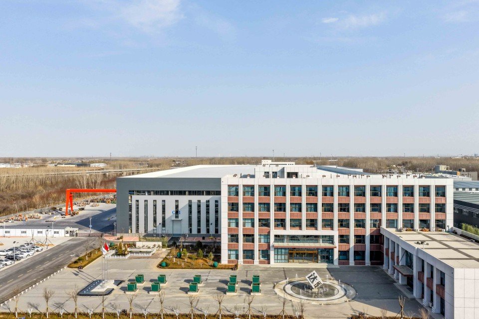
Why Source From Jinda Cable
Behind every drum we ship sits a 38-year track record, five production bases under one MES system, and a documentation discipline that gets cables through customs without delays.
-
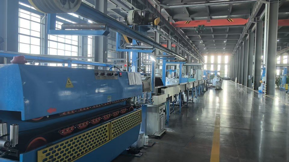
Every cable tested twice before shipping
Since 1987, our two-stage QC has been refined to a science: routine test on the production line, then full electrical and mechanical re-test before packing. Across 50+ export markets, our return rate stays under 0.3%.
-
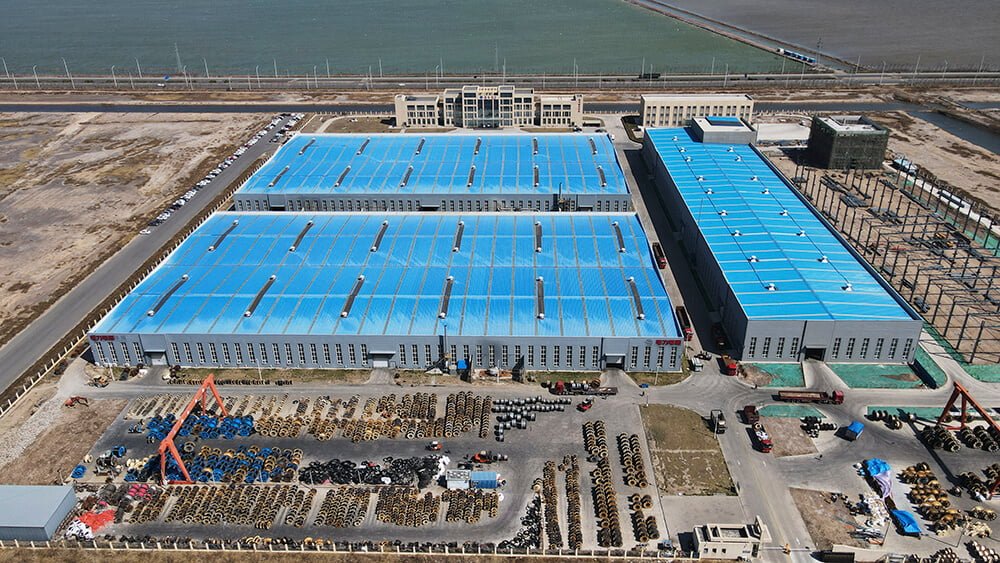
Five production bases, 470,000 m², synced via MES
Tianjin, Liaoning, Heilongjiang, Shandong, and Xian — each base runs under one unified MES system. Same recipe, same protocols, same traceability, regardless of which plant ships your order.
-
3,000+ SKUs, custom configurations welcome
Standard sizes ship from inventory. Special voltage grades, color-coding, drum lengths, or armor configurations are routine — submit your spec and our team will quote the lead time honestly.
-
Trusted by EPC contractors in 50+ countries
We supply utilities, mining operators, port authorities, and large industrial OEMs across Europe, the Americas, Southeast Asia, the Middle East, and Africa.
-
Full paperwork shipped with every order
Every shipment includes factory test report, certificate of origin (COO), packing list, and bill of lading (B/L). Customer-nominated witness testing can be arranged before shipment.
Our Track Record
98.7%
On-time shipment rate (last 24 months)
< 0.3%
Return rate across export markets
25 days
Typical sea freight Tianjin → Rotterdam
100%
Shipments with routine test report attached
Logistics & Delivery
Packaging, Shipping & Documentation
What we handle on our side from production floor to the port of loading. Product-specific installation guidance is supplied with the datasheet that accompanies each order.
Packaging
- Wooden or steel drums per IEC 62004
- Coil packaging available for small cross-sections
- Standard drum lengths plus custom lengths on request
- Each drum labeled with type, voltage, cross-section, length, batch
- Waterproof wrapping for export shipments
- Cable ends sealed against moisture ingress
- Private-label / OEM packaging available under NDA
Shipping
- FCL / LCL sea freight, air freight on request
- Trade terms: EXW, FOB, CFR, CIF, DDP
- Ports of loading: Tianjin / Qingdao / Shanghai
- Typical sea freight to Rotterdam: 25 days
- Lead time confirmed at order acknowledgement
- Container loading photos sent before sailing
Documentation
- Factory routine test report (per applicable standard)
- Commercial invoice and packing list
- Certificate of origin (CO) — China Council, FORM A, FORM E available
- Bill of lading (B/L) — original or telex release
- Third-party inspection by SGS / BV / TÜV on request
- Customer-nominated witness testing arranged before shipment
Get in Touch
Request a Quote for
XLPE Steel Wire Armored Power Cable
What You'll Receive
- Technical quotation with itemized FOB / CIF pricing
- Sample factory test report from a previous shipment
- Realistic lead time including raw-material procurement
- Direct contact with the assigned sales engineer


Email
info@jindacablegroup.comResponse Time
Within 1 business day
Related Products