A loose reading of “XLPE” can turn into the wrong cable on a purchase order, especially when voltage class, conductor temperature, flame behavior, and installation environment are treated as interchangeable details. On the plant floor, that mistake shows up as overheated feeders, failed commissioning tests, shortened service life, or a shutdown nobody budgeted for. The practical fix starts with understanding what XLPE actually means before comparing datasheets or chasing the lowest cable price.
XLPE stands for cross-linked polyethylene, a polyethylene-based insulation whose polymer chains are chemically or physically linked so they resist softening at higher temperatures. In cable buying, that usually means higher conductor temperature capability, better dielectric stability, and broader use across low-, medium-, and high-voltage power systems than ordinary PE insulation.
The acronym is simple; the engineering consequences are not. Cross-linking changes how the insulation behaves under heat, fault current, moisture exposure, bending, and long service duty, which is why XLPE appears in everything from 0.6/1 kV building feeders to engineered medium- and high-voltage projects built around IEC, ICEA, IEEE, or UL requirements.

What cross-linking changes
Cross-linking changes polyethylene from a material that mainly depends on chain entanglement into a chemically connected network. That is why XLPE can hold shape, electrical properties, and mechanical strength at temperatures where ordinary polyethylene would soften too much for dependable cable service. The advantage is not just “better plastic”; it is controlled chemistry plus controlled cable manufacturing.
Polyethylene itself is a simple idea with serious engineering consequences: it is a polymer made from long molecular chains of repeated ethylene units. In ordinary thermoplastic PE, those chains are not chemically tied together. They lie beside each other, coil, slide, and entangle. At normal service temperatures that can be perfectly useful, but when heat rises high enough, chain mobility increases and the material softens. Given enough temperature and stress, it can deform, creep, or flow.
Cross-linking adds chemical bridges between those long chains. Instead of behaving like a bowl of cooked noodles that can slide past each other, the material starts behaving more like a net. The chains can still move locally, so the insulation is not glass-hard, but large-scale flow is restricted. That three-dimensional network is what allows properly cross-linked polyethylene to resist melting and deformation at elevated cable temperatures.
That thermoplastic-versus-thermoset distinction matters on a plant floor and in a cable trench. Thermoplastic PE softens when heated enough and can be re-melted in processing. XLPE, once adequately cross-linked, is a thermoset insulation system: it does not simply melt back into a usable liquid. If it is overheated beyond its limits, it degrades rather than conveniently reprocessing. That is a strength in service and a drawback in recycling and scrap handling.
For many power cable designs, XLPE insulation is associated with conductor temperature ratings such as 90 °C continuous operation, 130 °C emergency operation, and 250 °C short-circuit withstand, depending on the governing standard, conductor size, insulation system, installation condition, and cable construction. Those numbers should not be copied blindly from one datasheet to another. They only mean something when the cable design, tests, accessories, and installation assumptions match the project requirements.
How cable manufacturers create the cross-linked network
The three common industrial routes are peroxide cross-linking, silane cross-linking, and electron-beam or irradiation cross-linking. None is automatically “best” in isolation. The right route depends on cable type, insulation thickness, production volume, voltage class, cleanliness requirements, and the manufacturer’s process control.
| Cross-linking route | How it works in practice | Where it is commonly considered | Practical trade-off |
|---|---|---|---|
| Peroxide cross-linking | Organic peroxide decomposes under heat and creates reactive sites that form cross-links between polymer chains | Widely used for power cable insulation, including demanding medium-voltage and high-voltage designs | Strong performance potential, but needs tight control of extrusion, curing, by-product removal, and cleanliness |
| Silane cross-linking | Silane-grafted polyethylene cross-links through a moisture-assisted reaction, often after extrusion | Often used in low-voltage and some medium-duty applications, depending on specification | Flexible production route, but cure uniformity depends on moisture, time, temperature, and insulation thickness |
| Electron-beam or irradiation cross-linking | High-energy radiation creates cross-links after extrusion | Used for selected cable types, thin insulation or sheath layers, and specialty products | No chemical peroxide residues, but equipment cost, penetration depth, and product geometry limit suitability |
Peroxide cross-linking is the route many engineers associate with higher-performance XLPE power cable. In continuous vulcanization lines, the insulation is extruded and then cured under controlled heat and pressure. For medium-voltage and high-voltage cables, the issue is not just getting the compound to cross-link; it is keeping the insulation and semiconductive shields clean, concentric, smooth, and free from voids or contamination. A tiny protrusion at the conductor shield interface may matter more electrically than a nice-looking outer jacket.
Silane systems are attractive because they can simplify some production arrangements and suit certain cable categories well. The catch is that cross-linking continues through a moisture-driven mechanism, so thick walls and storage conditions need attention. I have seen buyers treat silane XLPE as if the label alone guaranteed the same behavior as a fully controlled MV insulation system. That is not a safe assumption. Ask how the cure is confirmed, not just what the material is called.
Irradiation cross-linking has its place too, especially where post-extrusion treatment of thinner sections is practical. It can be very useful in selected wires, control cables, and specialty constructions. For heavy power cable insulation, geometry and penetration become serious commercial and technical constraints, so the method is chosen for the product family rather than as a universal upgrade.
Why the network improves cable performance
The main mechanism is reduced chain mobility. Under heat, electrical loading, bending stress, and compressive forces from installation, a cross-linked network resists permanent deformation better than uncross-linked PE. That helps the insulation keep its thickness, shape, and interface pressure around the conductor and shields.
Several service benefits come from that same mechanism:
- Heat deformation resistance: the insulation is less likely to flatten, flow, or creep under conductor heat and mechanical pressure.
- Short-circuit thermal endurance: during a fault, conductor temperature can rise sharply for a very short time; XLPE’s thermoset structure gives the insulation a better chance of surviving the event if the cable was correctly rated.
- Insulation stability: stable geometry supports predictable electric field distribution, especially around conductor shields and insulation shields.
- Long-term mechanical retention: aging under heat and load is slower when the material network resists chain slippage.
- Accessory compatibility: terminations and joints rely on insulation dimensions, surface condition, and shield interfaces staying within expected limits.
There is a trade-off here that procurement teams sometimes miss. Higher thermal capability can allow more current for a given conductor size, or more margin under difficult installation conditions, but it does not erase voltage stress, soil thermal resistance, tray grouping, harmonic heating, or poor termination work. The preferred choice flips when the limiting factor is not insulation temperature but installation heat dissipation, conductor loss, fire performance, chemical exposure, or project-specific approvals.
XLPE cable performance is determined only by the insulation material grade.False
The polymer network matters, but cable reliability also depends on compound cleanliness, extrusion quality, shield smoothness, degassing, moisture control, jacket design, installation workmanship, and correctly selected joints and terminations.
What production quality has to confirm
A cross-linked material should be verified, not assumed. In cable manufacturing and quality assurance, practical indicators include gel content, hot set testing, and thermal elongation. The exact acceptance criteria depend on the applicable standard, buyer specification, voltage class, and manufacturer’s documented process controls.
Gel content is used to estimate how much of the polymer has become insoluble due to cross-linking. It is not a magic number by itself, but it gives a useful indication of whether the network formed adequately. Too little cross-linking can leave insulation prone to thermal deformation; excessive or poorly controlled curing can create other problems, including material degradation or process instability.
Hot set testing looks at how the insulation stretches under load at elevated temperature and how well it recovers. Thermal elongation is especially practical because it connects laboratory behavior with what field engineers care about: will the insulation keep its shape when the cable is hot and under stress? If a factory operator is chasing line speed and the cure is marginal, these tests are where the shortcut tends to show up.
Degassing is another detail that deserves respect, particularly for peroxide-cross-linked MV and HV cables. Peroxide curing can leave volatile by-products that must diffuse out before the cable is tested, shipped, or installed according to the manufacturer’s process and project requirements. Rushing this stage may save calendar time in production but can create electrical test risk or long-term reliability concerns. Good cable factories treat degassing space, reels, temperature, and time as production constraints, not housekeeping.
The boundary is clear: cross-linking improves the insulation material’s thermal and mechanical behavior, but it does not compensate for dirty compound handling, eccentric extrusion, rough semiconductive shields, moisture ingress, undersized jackets, damaged pulling practices, or badly made accessories. In medium-voltage and high-voltage cables especially, XLPE should be understood as a manufactured insulation system, not a coating poured around copper or aluminum.
Electrical and thermal performance
XLPE is specified because it gives a useful combination of high dielectric performance and higher permissible conductor temperature than many older thermoplastic insulation systems. In plant terms, that means the cable can carry AC power reliably with low electrical loss, tolerate normal load cycling, and survive specified fault events — provided the whole cable system is selected and installed for the actual route, not just the insulation name.
Why XLPE works well as power-cable insulation
For alternating-current transmission and distribution, the insulation has to do several jobs at once. It must withstand voltage stress, resist leakage current, stay dimensionally stable under heat, and avoid becoming a source of excessive dielectric heating. XLPE is strong in this package of properties, which is why it is common from low-voltage 0.6/1 kV feeders up through medium-voltage and high-voltage cable systems, depending on shielding, screen design, jointing, termination design, and the governing standard.
The main electrical properties engineers care about are:
- Dielectric strength: the ability of the insulation to resist breakdown under electrical stress. In MV and HV cables, the stress is not evenly distributed unless the conductor screen, insulation, and insulation screen are clean, smooth, and well bonded as a system.
- Insulation resistance: resistance to leakage current through the insulation. Good insulation resistance matters during commissioning tests, but it also gives maintenance teams a baseline for later comparison.
- Low dielectric loss: XLPE has low loss under AC voltage, so less energy is converted into heat inside the insulation. This becomes more important as voltage level, cable length, and operating duty increase.
- Thermal stability under load: because XLPE is cross-linked, it does not soften and flow like ordinary polyethylene when it gets hot. That helps the cable hold its insulation geometry during load peaks and fault events.
There is a mechanism behind the low-loss advantage. Under AC voltage, insulation molecules polarize and relax every cycle. If the insulation system has high dielectric loss, that microscopic movement shows up as heat. Heat then raises conductor and insulation temperature, which can reduce life and, in a poor installation, push the cable into a slow failure loop. XLPE keeps that loss relatively low, but the screen interfaces, contaminants, voids, moisture, and accessory workmanship still decide whether the installed circuit behaves like the type-test report.
Temperature ratings are design limits, not daily operating targets
Many XLPE power cables are designed around conductor temperature limits of 90 °C for continuous operation, 130 °C for emergency operation, and 250 °C for short-circuit withstand. Those values are common in power-cable practice, but they are not universal permissions; the final allowable temperatures come from the applicable standard, cable construction, joint and termination ratings, installation conditions, and project specification.
Many XLPE power cable designs use 90 °C continuous, 130 °C emergency, and 250 °C short-circuit conductor temperature values.True
These are common values in many power cable standards and specifications, but they must be verified against the exact cable design, accessories, installation method, and governing project documents.
The distinction matters in procurement. A cable marked for a 90 °C conductor does not mean the plant should run it at 90 °C every afternoon. It means the insulation system is designed to tolerate that conductor temperature under the defined conditions. Running cooler usually improves life, reduces thermal expansion stress at terminations, and gives the plant some breathing room when the tray gets another circuit added six months after commissioning — which, in my experience, happens more often than the original cable schedule admits.
Temperature also affects accessories. A straight run of cable may be properly rated, while the weak point is a heat-shrink termination installed inside a dusty panel with poor ventilation, or a joint bay where water sits after rain. The thermal rating of the insulation is only one part of the circuit rating.
How thermal rating connects to ampacity
XLPE can support a higher permissible conductor temperature than many PVC-insulated power cables, so it often allows a higher current rating for the same conductor size under comparable conditions. That is the simple version. The engineering version is that ampacity is a heat-balance problem: current creates conductor losses, the insulation and sheath resist heat flow, and the installation environment must remove that heat fast enough to keep the conductor below its limit.
Actual current rating depends on:
| Factor | Why it changes ampacity |
|---|---|
| Conductor material and size | Copper and aluminum have different resistance; larger conductors reduce I²R losses but cost and bend radius increase. |
| Installation in air, tray, duct, or ground | Free air removes heat differently from buried duct banks or tightly packed trays. |
| Grouping with other circuits | Adjacent loaded cables heat each other; derating can be substantial in congested routes. |
| Soil thermal resistivity | Dry sandy soil can trap heat; wet compact soil usually dissipates heat better. Seasonal drying around heavily loaded buried cables is a real issue. |
| Ambient temperature | A cable in a 45 °C outdoor tray has less thermal headroom than one in a cooled electrical room. |
| Load factor | Constant process loads heat the route differently from intermittent motors or standby feeders. |
| Ducts, conduits, and trench details | Air gaps, concrete encasement, duct material, and burial depth all change heat transfer. |
The trade-off is familiar to anyone who has had to defend a cable schedule. You can use XLPE’s higher temperature capability to reduce conductor size or keep an existing route within rating, but you may sacrifice voltage-drop margin, fault capacity, future load growth, and operating life. The preferred choice flips when power losses, outage risk, or expansion plans are more expensive than the extra copper or aluminum bought at the start.
A higher temperature rating is best treated as operating margin, not an invitation to run the cable hot for its whole life. That conclusion stops holding only where the project has deliberately designed for high-load operation, verified all derating factors, and accepted the life-cycle and maintenance implications.
Short-circuit withstand is a system check
During a short circuit, the cable is not judged by steady ampacity. It is judged by how much thermal and electromechanical stress it can survive before the protective device clears the fault. The conductor heats rapidly because fault current is high and duration is short; there is little time for heat to escape into the surrounding soil or air. That is why conductor thermal capacity, initial conductor temperature, and clearing time are central to short-circuit calculations.
For XLPE cables, the insulation must remain stable during the specified short-circuit event, often associated with a 250 °C conductor temperature limit in many designs. But the insulation is not the only item at risk. Engineers should verify:
- conductor short-circuit rating for the selected material and cross-section;
- metallic screen or concentric neutral fault-current capacity;
- armor rating and bonding method, especially where armor may carry fault current;
- sheath and oversheath behavior under thermal stress;
- joint and termination short-circuit withstand;
- protective relay and fuse clearing time at the actual fault level;
- earthing arrangement and touch-voltage requirements.
A common mistake is checking only the phase conductor. In MV cable networks, the metallic screen can be the limiting component during earth faults. If the screen cross-section is undersized or bonded incorrectly, the cable may pass normal load checks and still be wrong for the fault duty. Standards such as IEC 60502, IEC 60840, IEC 62067, ICEA documents, and project-specific IEEE requirements may all be relevant, depending on voltage class and region.
Long-term concerns: water trees and electrical trees
XLPE has strong electrical performance, but it is not magic. In medium-voltage and high-voltage service, long-term insulation aging often comes down to local stress concentration, moisture, contamination, and interface quality. Two terms appear often in failure analysis: water treeing and electrical treeing.
Water trees are microscopic, moisture-assisted degradation patterns that can develop under electric stress. They do not immediately behave like a clean puncture through the insulation, but over years they can reduce dielectric strength and increase the risk of failure. Electrical trees are more aggressive discharge-driven channels that can grow from defects, protrusions, voids, or damaged interfaces until breakdown occurs.
Risk reduction starts before the cable ever reaches site:
- clean XLPE compound and controlled extrusion;
- smooth conductor screen and insulation screen interfaces;
- triple extrusion for MV and HV insulation systems where specified;
- water-blocking tapes, powders, or longitudinal barriers where the route demands it;
- radial moisture barriers for more severe wet environments, when specified;
- correct sheath selection for abrasion, chemicals, sunlight, termites, or hydrocarbons;
- factory tests and routine tests aligned with IEC 60811, IEC 60502, IEC 60840, IEC 62067, UL 44, ICEA, or the project specification, as applicable.
Site workmanship then has to preserve what the factory produced. A shaving nick under a termination screen, dirty gloves during jointing, or a poorly parked semiconductive layer can create a stress point that no insulation material will forgive. Cable pulling damage is another quiet culprit; excessive sidewall pressure around a bend can deform layers before anyone energizes the circuit.
The best XLPE cable selection is often not the cable with the most impressive headline temperature or voltage rating. It is the cable whose insulation system, metallic screen, sheath, armor, fire behavior, water-blocking design, and accessories match the installation environment and the maintenance reality of the plant. A clean indoor substation feeder, a buried mine supply cable, a coastal utility circuit, and a crowded petrochemical tray may all use XLPE, but they should not be bought as if insulation material alone defines the specification.
XLPE versus common insulations
XLPE is usually the stronger default for fixed power feeders where temperature rating, dielectric strength, and service life matter, but it is not automatically “better” for every cable. PVC, PE, EPR, rubber, mineral-insulated, and specialty constructions each win under certain combinations of voltage, movement, fire duty, chemical exposure, and installed cost.

XLPE vs PVC
PVC remains popular because it is economical, easy to process, flexible enough for many building and control cables, and familiar to almost every electrical contractor. For low-voltage lighting circuits, small power wiring, panels, and general plant distribution, a PVC-insulated cable can be the sensible purchase if the specification allows it and the thermal loading is modest.
The main engineering difference shows up when conductor temperature and electrical stress rise. Many XLPE power cable designs are associated with 90 °C continuous conductor operation, with emergency and short-circuit limits defined by the applicable standard and cable construction. PVC commonly sits lower in allowable operating temperature, especially in general-purpose grades, so the same conductor size may run closer to its thermal limit under heavy feeder duty.
The mechanism is simple enough: heat softens thermoplastic insulation. PVC is a thermoplastic compound; under sustained heat and pressure, especially at terminations or tight cleats, it can deform more readily than cross-linked insulation. XLPE has a molecular network that resists flow after cross-linking, so it holds its shape better at elevated conductor temperature. That matters in large feeders where a summer peak, a dirty cable tray, or a bundled section through a riser can quietly raise operating temperature.
PVC still has practical advantages. It often gives good mechanical toughness in smaller sizes, bends nicely in control wiring, and can be compounded for flame retardance. It is also easy to identify, strip, and terminate. The trade-off is that a buyer can save money upfront but give away ampacity margin, thermal aging margin, or suitability for medium-voltage service. In my experience, PVC is often chosen correctly for branch circuits and small LV runs; it is chosen badly when someone extends that habit into heavily loaded mains without checking the thermal calculation.
XLPE vs ordinary polyethylene
PE has good electrical properties, low dielectric loss, and strong moisture resistance, which is why polyethylene-based materials have a long history in communication and power cable applications. Ordinary PE, though, is not cross-linked. At higher temperature it behaves like a thermoplastic, so dimensional stability becomes the limiting issue before the base electrical properties are exhausted.
XLPE keeps much of the electrical character of polyethylene while improving high-temperature stability through cross-linking. The polymer chains are tied into a network, so the insulation does not melt and flow in the same way as uncross-linked PE. In power cable service, that means better resistance to deformation around the conductor screen, insulation screen, and areas near joints where local heating and pressure can be concentrated.
There is still a procurement trade-off. XLPE production, curing, degassing, cleanliness control, and medium-voltage screening systems are more demanding than ordinary PE insulation for simpler cable types. If the application is low-stress, low-temperature, moisture-sensitive, and not a power feeder, PE may be entirely appropriate. Once the cable is expected to carry serious load at elevated conductor temperature, XLPE normally gives the safer engineering margin. That conclusion stops holding if the environment, not conductor heat, is the dominant failure driver, such as severe chemical attack or a fire-survival circuit.
XLPE vs EPR and rubber-based insulations
EPR and other rubber-based insulations are not “old-fashioned alternatives”; they solve some problems better than XLPE. EPR can offer excellent flexibility, good moisture tolerance, and robust performance in applications where the cable moves, vibrates, is reeled, or lives in rough handling. Mining cables, marine systems, trailing cables, temporary power, shipboard applications, and some portable industrial feeds often lean toward rubber-type constructions for good reasons.
XLPE, by contrast, is often preferred for fixed power distribution, utility feeders, industrial substations, plant mains, and many buried or duct-installed cables. It works well where the cable is installed once, properly supported, terminated with compatible accessories, and left to operate for years. Its dielectric performance and thermal rating make it a natural fit from 0.6/1 kV low-voltage cables into medium-voltage and high-voltage designs, depending on shielding, insulation thickness, accessories, and standards such as IEC 60502, IEC 60840, IEC 62067, ICEA, or IEEE project specifications.
The choice can flip quickly when bending and handling dominate. A large XLPE feeder may meet the electrical specification but fight the installer in a cramped pump room, especially in cold weather. EPR or rubber insulation may cost more and may have different diameter, termination, or aging considerations, yet it can reduce installation damage and nuisance failures in movable service. A plant that drags a “fixed” cable across a concrete floor every shutdown should stop calling it fixed service and specify accordingly.
XLPE vs mineral-insulated and specialty high-temperature cables
XLPE is not the answer for every high-temperature or fire-critical duty. Furnace zones, ladle areas, glass plants, engine exhaust areas, emergency life-safety circuits, and certain petrochemical units may require mineral-insulated metal-sheathed cable, mica-taped fire-resistant cable, silicone rubber, fluoropolymer, or other specialty systems. These are not interchangeable with ordinary XLPE power cables.
The distinction is between surviving normal electrical loading and maintaining function during an extreme event. XLPE may tolerate high conductor temperature under rated operation, but that does not mean it will maintain circuit integrity during a fire, direct flame exposure, molten splash, or a severe chemical release. Fire-survival cable is selected as a complete tested system, often including conductor, insulation barrier, sheath, armor, support method, joints, glands, and installation practice.
Do not confuse insulation with the outer jacket
An XLPE-insulated cable may have many different sheath materials. The sheath is selected for the environment, not just for the insulation acronym printed on the datasheet.
| Cable layer or requirement | Common choices | What the buyer should verify |
|---|---|---|
| Insulation | XLPE, PVC, PE, EPR, rubber, specialty polymers | Voltage class, temperature rating, dielectric performance, applicable standard |
| Outer sheath or jacket | PVC, PE, LSOH, chlorinated polyethylene, rubber compounds, other specified materials | Flame spread, sunlight resistance, oil resistance, abrasion, water exposure, termite or rodent risk, chemical compatibility |
| Fire behavior | Flame-retardant, low-smoke, halogen-free, fire-resistant constructions | Tested result under IEC 60332, IEC 60754, IEC 61034, or project fire standard |
| Mechanical protection | Armor, metallic sheath, screen, bedding, reinforced jacket | Pulling tension, impact risk, burial conditions, grounding, corrosion exposure |
A common procurement mistake is writing “XLPE cable” and assuming the rest of the construction is implied. It is not. A buried feeder in wet soil, a tray cable in a refinery, a rooftop solar run, and a tunnel power cable may all use XLPE insulation, yet need different sheaths, armor, screens, flame performance, and accessory systems.
An XLPE-insulated cable is automatically low-smoke, halogen-free, or fire-survival rated.False
XLPE describes the insulation polymer, not the complete cable fire performance. Smoke density, halogen acid gas, flame spread, and circuit integrity depend on sheath, fillers, bedding, armor, mica barriers, installation method, and tested standards such as IEC 60332, IEC 60754, IEC 61034, or project-specific fire-resistance requirements.
A practical selection framework for procurement
For technical buying, compare insulation systems against the service conditions first, then compare price. A tidy spreadsheet that lists only conductor size and voltage class misses the failures that actually cost money on site.
Use these checks before approving an insulation type:
- Voltage class and standard
Confirm whether the cable is LV 0.6/1 kV, medium voltage, or high voltage, and tie it to the correct standard family, such as IEC 60502 for many LV and MV applications, or IEC 60840 and IEC 62067 for higher-voltage systems where applicable. - Continuous and emergency temperature requirement
Check the required conductor temperature rating against load profile, grouping, soil thermal resistivity, tray ventilation, ambient temperature, and short-circuit duty. Nameplate rating alone does not guarantee safe ampacity. Installation environment
Separate indoor tray, buried duct, direct burial, wet tunnel, marine, mining, rooftop, and chemical plant service. The jacket and protection system may drive the specification as much as the insulation.Flexibility and movement
Fixed utility feeder service suits XLPE well. Portable, reeling, trailing, or high-vibration duty may justify EPR or rubber-based designs even at a higher cable price.Fire and smoke requirements
Specify flame retardance, low smoke, halogen-free behavior, acidity, and circuit integrity by tested standard, not by assumption. IEC 60332, IEC 60754, and IEC 61034 address different fire-performance properties.Accessories and installation skill
Medium-voltage XLPE systems depend heavily on compatible joints, terminations, screen handling, cleanliness, and trained installers. A good cable can still fail early because a stress cone was fitted on a dusty afternoon with the wrong kit.Lifecycle cost and supplier capability
Include losses, derating, expected life, outage cost, spare length, accessories, documentation, test reports, delivery reliability, and after-sales support. The cheapest insulation choice is rarely cheap after one unplanned feeder failure.
The right comparison is not XLPE versus every other material in isolation; it is complete cable construction versus the electrical duty, site environment, installation method, and required proof of compliance. That is where acronyms stop being useful and engineering specification starts.
Where XLPE cables fit
XLPE cables fit best in fixed power distribution where thermal margin, dielectric strength, service life, and predictable procurement standards matter more than frequent flexing. You see them from 0.6/1 kV building feeders up through medium-, high-, and extra-high-voltage networks, but the cable construction around the XLPE changes heavily with voltage, installation risk, and local code.
Utility distribution and grid expansion
Utilities use XLPE heavily in medium-voltage feeders, underground distribution circuits, substations, ring main unit connections, transformer feeders, and urban grid reinforcement. In practice, the attraction is not just the insulation name; it is the way XLPE supports compact, thermally capable cable systems that can be standardized across long procurement programs.
Typical utility applications include:
- Medium-voltage underground feeders between primary substations, switching stations, and distribution transformers.
- Urban distribution circuits where overhead lines are restricted by space, aesthetics, weather exposure, or public-safety requirements.
- Substation cable exits and transformer connections, often with metallic screens sized for earth-fault duty.
- Ring main unit and compact switchgear connections, where termination quality and bending space are just as important as the cable rating.
- Grid expansion projects where repeatable cable types simplify spares, jointing kits, and crew training.
The mechanism is straightforward: higher allowable conductor temperature can improve current-carrying capability, but only if soil thermal resistivity, grouping, duct fill, screen losses, and termination ratings allow it. A cable that looks generous on a datasheet can still run hot in a congested duct bank under a city road, especially after years of added circuits nobody modeled properly.
Industrial plants and heavy electrical loads
In industrial plants, XLPE is commonly used for main feeders, motor control centers, large motors, pumps, compressors, conveyors, process distribution boards, and furnace-area power circuits outside extreme-temperature zones. I would expect to see it in cement plants, chemical plants, water treatment works, steel service areas, packaging lines, and general manufacturing power rooms.
Good candidates include:
- Plant incoming feeders from transformers to main switchboards.
- Motor control center feeders serving multiple drives and starters.
- Large fixed motors for pumps, fans, mills, crushers, and compressors.
- Conveyor and materials-handling systems with fixed cable routes.
- Process plant distribution systems where chemical resistance depends mainly on sheath choice, not insulation alone.
- Furnace support equipment located away from radiant heat, slag splash, or continuous high ambient temperature.
The trade-off is flexibility. XLPE power cable is usually a fixed-installation product; it does not like being dragged, reeled, twisted, or driven over by forklifts every shift. For mining shovels, portable pumps, welding leads, festoon systems, or trailing equipment, a flexible rubber-insulated cable may be the better engineering choice even if XLPE looks stronger thermally on paper.
Commercial, transport, and public infrastructure
Airports, rail facilities, tunnels, data centers, hospitals, ports, campuses, high-rise buildings, and public utility corridors all use XLPE cables, but fire behavior often becomes the controlling requirement. The insulation can be XLPE while the overall cable must still meet project rules for flame spread, halogen acid gas, smoke density, circuit integrity, or low-smoke zero-halogen sheathing.
Common design pressures are different by site:
| Project type | Why XLPE is used | What must be checked |
|---|---|---|
| Data centers and hospitals | High-load feeders, reliability, clean routing | Fire rating, redundancy, emergency power segregation |
| Tunnels and rail stations | Long feeders in confined spaces | Smoke, toxicity, flame spread, mechanical protection |
| Airports and ports | Large distributed loads over wide areas | Moisture, UV, impact, maintenance access |
| High-rise buildings | Riser feeders and main distribution | Installation method, derating, local fire code |
| Campuses and utility corridors | Standardized underground distribution | Duct capacity, joint bays, future expansion |
This is where procurement mistakes happen. A buyer asks for “XLPE cable” and assumes that covers the building requirement. It does not. The jacket compound, armor, screen, fire performance, voltage designation, conductor class, and test standard have to be specified separately.
Renewable energy systems
Solar farms, wind farms, battery energy storage systems, and grid connection feeders often use XLPE-insulated cables because the networks are large, fixed, and thermally loaded for long operating periods. Solar collection circuits and inverter station feeders see daily heating cycles; wind farm internal networks may run through long underground routes; BESS interconnections can have concentrated load, fault-current, and fire-separation requirements.
For renewable projects, the surrounding construction matters as much as the insulation:
- UV exposure if any cable is above ground or on open trays.
- Moisture resistance and water-blocking for buried runs and wet trenches.
- Grounding and screen design for fault clearing and induced voltage control.
- Thermal cycling at terminations, especially on outdoor equipment that heats in sun and cools hard at night.
- Rodent, termite, or mechanical protection depending on terrain and site maintenance habits.
The preferred design can flip with installation method. A solar plant with well-controlled trenches may use armored or non-armored XLPE designs depending on local practice; rocky ground, poor backfill, or aggressive rodents can justify heavier mechanical protection even when it costs more and slows installation.
Mining, oil, gas, marine, and difficult environments
Mining, oil, gas, and heavy industry use XLPE for fixed distribution where mechanical protection, sheath resistance, armor, and regulatory compliance are essential. It may be suitable for substations, fixed pump stations, processing plants, workshops, and permanent power distribution, but not automatically for mobile mining equipment or constantly flexing offshore service loops.
Submarine, marine, and offshore-adjacent systems can also use XLPE insulation in selected power cables, including fixed offshore platform distribution, export-related systems, harbor power, and subsea or nearshore routes. These are not catalog-cable decisions. Water pressure, corrosion, armoring, bend radius during laying, dynamic movement, approvals, and repair philosophy drive the design.
Underground, direct-buried, and higher-voltage systems
For underground and direct-buried installations, XLPE insulation is commonly combined with metallic screens, water-blocking tapes or powders, aluminum or steel wire armor, PE outer sheaths, termite-resistant sheaths, or special jackets according to soil, moisture, impact, and fault-current requirements. The insulation handles the electric field; the rest of the cable handles the ground.
XLPE is not limited to low-voltage cable; it is used from 0.6/1 kV systems through medium-, high-, and extra-high-voltage power cables when the full cable design and testing are appropriate.True
XLPE is widely specified across voltage classes, but higher voltage levels require more controlled conductor screens, insulation screens, metallic sheaths or screens, joints, terminations, and type/routine testing under standards such as IEC, ICEA, IEEE, UL, or project-specific specifications.
As voltage rises, construction tolerance tightens sharply. A low-voltage XLPE cable may be forgiving of ordinary handling; an EHV cable system is closer to an engineered asset, with factory cleanliness, extrusion control, partial-discharge performance, sheath bonding, jointing workmanship, and commissioning tests all tied together. The practical boundary is simple: XLPE tells you the insulation family, not the finished cable’s suitability for a site. That suitability comes from matching voltage class, installation environment, fire rules, mechanical risk, fault duty, and the current standard or project specification before the purchase order is released.
Cable construction around XLPE
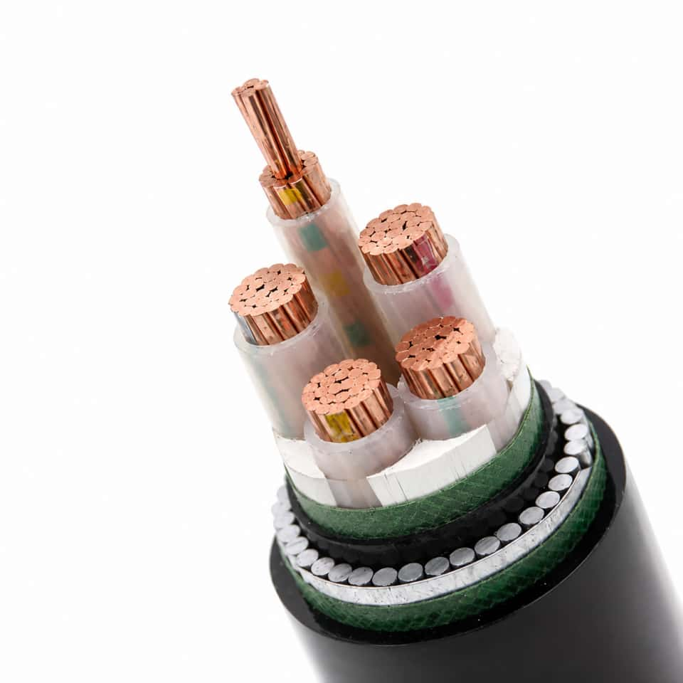
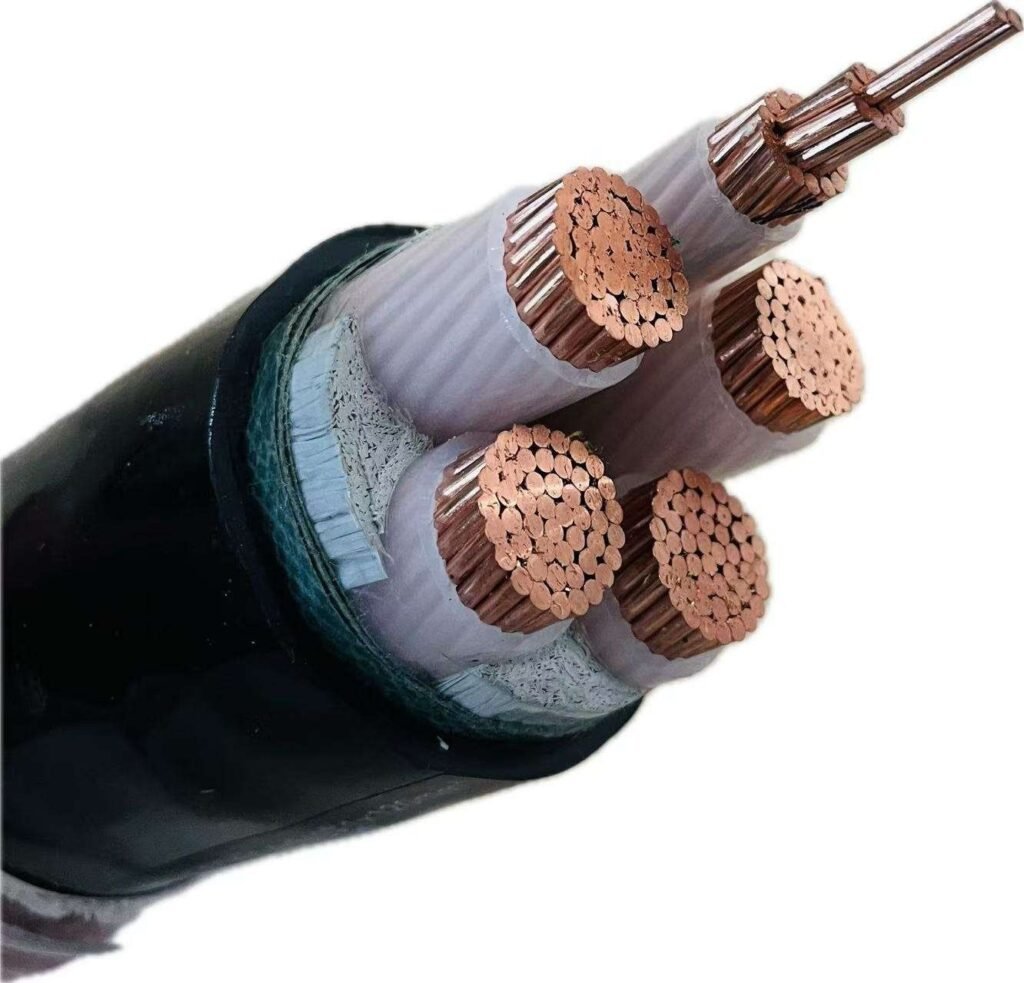
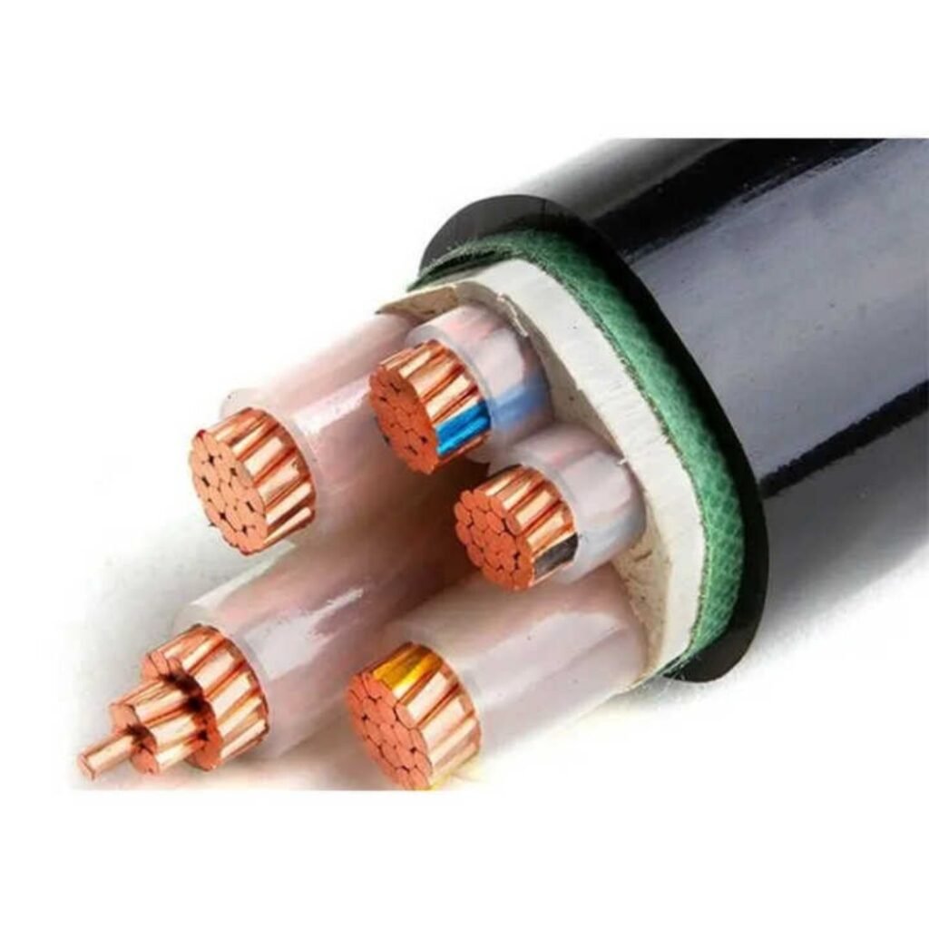
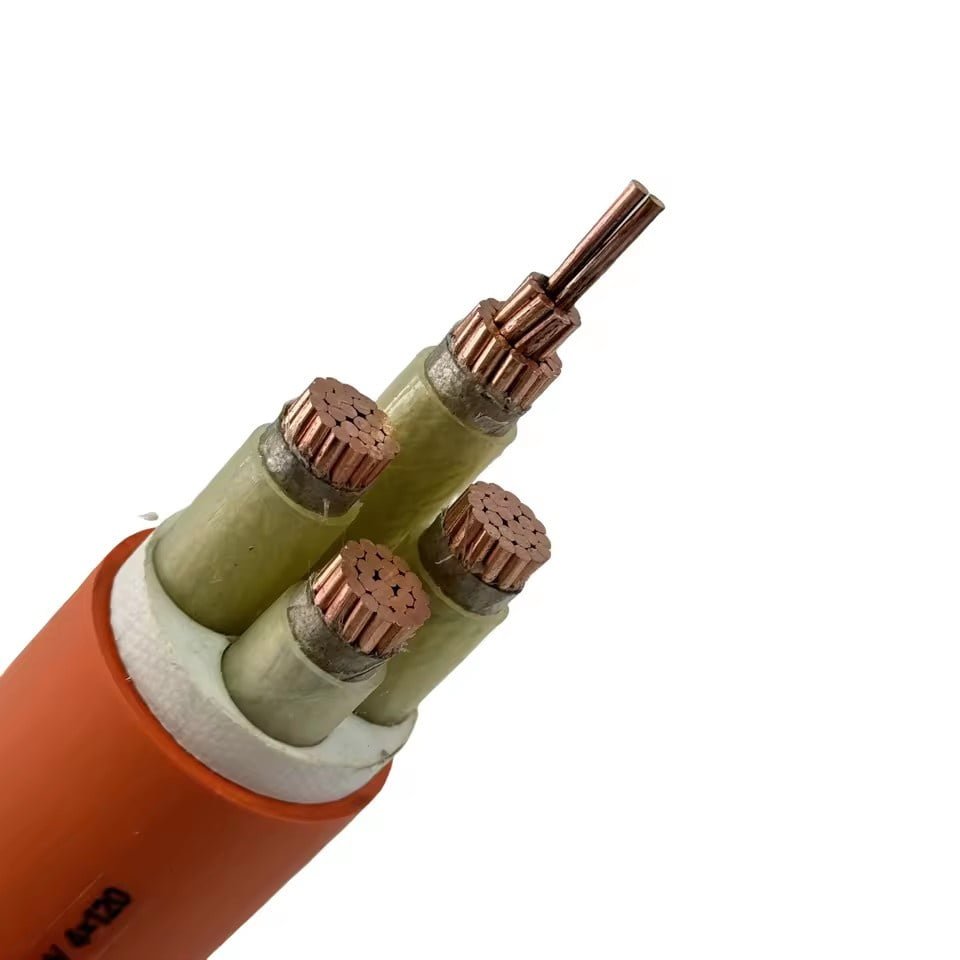
An XLPE cable only performs as specified when the surrounding construction is selected correctly. The insulation may carry the temperature and voltage rating on the datasheet, but conductor design, screens, shield, water blocking, armor, sheath, and marking determine whether that rating survives pulling, termination, moisture, fault current, and years of operation.

For procurement, I would not buy “XLPE cable” as a material description alone. A usable RFQ should describe the full build-up, because two cables with the same conductor size and XLPE insulation can behave very differently in a wet duct bank, on a tray in a refinery, or buried beside a haul road.
| Cable element | What it does in service | What buyers and engineers should verify |
|---|---|---|
| Conductor | Carries load current and short-circuit current | Copper or aluminum, size, resistance class, stranding, compaction, DC resistance, voltage drop, fault duty |
| Conductor screen | Smooths electric stress at the conductor surface in MV and higher cables | Semi-conductive material, extrusion quality, compatibility with insulation |
| XLPE insulation | Provides dielectric separation and thermal endurance | Thickness, concentricity, cleanliness, curing quality, applicable standard |
| Insulation screen | Controls the electric field outside the insulation | Strippable or bonded design, screen removal behavior, termination compatibility |
| Metallic screen or shield | Provides grounding, fault-current path, shielding, and touch-voltage control | Copper tape, copper wire, aluminum laminate, fault rating, grounding method |
| Water blocking | Limits moisture migration and water-tree risk | Longitudinal tapes or powders, radial barrier, wet-location requirement |
| Bedding, fillers, binders | Hold cable geometry and protect cores | Circularity, material compatibility, extrusion support |
| Armor | Protects against mechanical damage and pulling loads | Steel wire, steel tape, aluminum wire, corrosion protection, magnetic losses |
| Outer sheath | Protects against environment and installation abuse | PVC, PE, LSOH, flame-retardant, UV-resistant, oil-resistant, anti-termite, special compounds |
| Marking and traceability | Supports installation, inspection, and asset records | Voltage, standard, size, manufacturer ID, batch, length marks, project labels |
The conductor decision usually starts with copper versus aluminum. Copper gives lower resistance in a smaller cross-section and is easier to terminate in crowded panels; aluminum reduces weight and often material cost, but needs larger size for the same ampacity and demands disciplined jointing practice. Stranded and compacted conductors are not cosmetic choices either. Compaction improves circularity and can reduce cable diameter, while stranding class affects flexibility, pulling behavior, and termination hardware. The selected size has to satisfy load current, installation derating, voltage drop, and short-circuit withstand, not just a nameplate amperage.
In medium-voltage and higher XLPE cables, the conductor screen is one of the layers that separates a professional cable from a dangerous approximation. Bare stranded conductors have ridges, air gaps, and local high-stress points. A semi-conductive conductor screen creates a smoother electrical interface so the field enters the XLPE insulation evenly instead of concentrating at strand edges. Poor bonding, contamination, or extrusion defects at this interface can become partial-discharge starting points; you may not see the problem during delivery inspection, but the cable can age badly once energized.
The XLPE insulation itself needs controlled thickness, concentricity, cleanliness, and cross-linking quality. Thickness is tied to voltage class and the governing standard or project specification; it should not be casually reduced to save diameter. Concentricity matters because the thinnest side of an off-center insulation wall sees the highest electrical stress. Cleanliness matters because small contaminants, scorch particles, or voids can disturb the dielectric field. In higher-grade production, the conductor screen, insulation, and insulation screen are commonly co-extruded to reduce interface contamination, but the exact process and test regime must be confirmed with the manufacturer’s documentation.
The insulation screen is the semi-conductive layer over the XLPE. Its job is to keep the outer surface of the insulation at a controlled electrical potential and transfer the field to the metallic screen or shield. For installers, the practical issue is stripping and termination. A screen that strips poorly can leave semi-conductive residue, cuts, or roughness on the insulation surface, and those small workmanship defects are a common cause of MV accessory failures. This is where cable design and accessory selection have to be treated as one package, not two separate purchases.
Metallic screening is not just “some copper around the cable.” Copper tape, copper wire, aluminum laminate, and other shield systems behave differently under fault current, bending, moisture exposure, and grounding arrangements. Copper wire screens usually offer better flexibility and can be sized for higher earth-fault current, while copper tape gives coverage but may be more sensitive to repeated bending. Aluminum laminate or metal-polymer barriers can help with radial moisture protection, but termination and bonding details become more specific. The shield must be sized and grounded for the actual system fault level and protection clearing time, not copied from a previous project because the voltage rating looks similar.
Water blocking is where a lot of buried and duct-installed cable specifications are either sensible or too optimistic. Longitudinal water-blocking tapes and powders swell when moisture enters, slowing travel along the cable. Radial barriers, such as laminated metallic sheaths or other moisture-blocking constructions, help stop water from entering through the sheath wall. The mechanism is simple enough: moisture plus electrical stress can support water-tree growth in polymer insulation over time, especially where defects or shield interfaces give it a path. For dry indoor LV tray runs, elaborate water blocking may be unnecessary; for wet ducts, direct burial, tunnels, coastal plants, and wind or solar collection systems with standing water in conduits, it can be the difference between normal aging and premature replacement.
Bedding, fillers, and binders look unglamorous, but in multicore cables they preserve the round shape that the sheath and armor depend on. Bad filler selection can make the cable oval, create pressure points, or let cores shift during pulling. I have seen crews blame a sheath for tearing when the deeper problem was a lumpy cable core under the jacket.
Armor selection is a mechanical and electrical trade-off. Steel wire armor handles tensile load and abuse well, steel tape gives impact protection in many buried installations, and aluminum wire or other non-magnetic armor is often preferred around single-core AC power cables to avoid magnetic heating losses. The choice flips when corrosion, pulling tension, rodent risk, route bending, or installation in a hazardous plant becomes the dominant concern.
The outer sheath is the cable’s daily workwear. PVC is common and economical, PE gives strong moisture and abrasion resistance, LSOH is selected where smoke and halogen acid gas must be reduced, and special sheath compounds may be needed for oil, UV, termite exposure, mud, salt, or chemical contact. Flame behavior should be verified against the specified test references, such as IEC 60332, IEC 60754, or IEC 61034 where applicable, rather than assumed from a color or sheath name.
Marking closes the loop between procurement and maintenance. Voltage grade, conductor size, standard reference, manufacturer identification, batch data, length marks, and project-specific tags help installers pull the right drum and help maintenance teams identify the circuit years later. On large projects, traceability is not paperwork decoration; it is how you isolate a batch, match test certificates to delivered drums, and avoid cutting into the wrong spare length during a shutdown.
Standards and test evidence
A buyer should accept XLPE cable against a controlled specification, not against the letters “XLPE” on a datasheet. The useful evidence is a package of applicable standards, factory test records, material traceability, inspection records, and project-specific checks that prove the cable supplied matches the voltage class, installation duty, fire requirement, and procurement contract.
Which standards normally apply to XLPE power cables?
For international projects, the first split is usually voltage class. IEC 60502 is commonly used for low-voltage and medium-voltage power cables, IEC 60840 for high-voltage cables, and IEC 62067 for extra-high-voltage cables. Conductor requirements are often tied back to IEC 60228, while insulation, sheath, aging, hot set, and mechanical test methods often reference IEC 60811 or the relevant product standard.
Destination market can change the paperwork quickly. A cable package for a Gulf utility, an Australian mine, a North American industrial plant, and a European infrastructure project may all be “XLPE,” but the accepted standard set may differ.
Common references include:
- IEC families: IEC 60502, IEC 60840, IEC 62067, IEC 60228, IEC 60332, IEC 60754, IEC 61034, IEC 60811.
- North American references: UL 44, ICEA standards, IEEE project specifications, and utility purchase specifications.
- British and Commonwealth references: BS standards and AS/NZS standards, depending on the market and installation rule.
- Utility or owner specifications: screen fault current, oversheath testing, drum length tolerance, cable marking, color coding, packing, and witness hold points.
In practice, the project specification should name the exact standard edition, voltage designation, conductor class, conductor material, insulation screen system, metallic screen or armor requirement, sheath compound, fire-performance requirement, and test scope. If those items are left vague, the supplier may still build a compliant cable, but not necessarily the cable your site engineer thought was being purchased.
Routine electrical tests before release
Routine tests are the minimum factory checks performed on production lengths or manufacturing lots, depending on the standard and cable type. They are not a substitute for type testing, but they are the first line of defense against obvious production defects before drums leave the plant.
Typical routine electrical tests include:
- Conductor resistance test
This confirms conductor size, material, stranding quality, and joint integrity. A resistance value outside tolerance may point to wrong conductor cross-section, poor compaction, material mix-up, or temperature correction errors during measurement. Voltage test
The completed cable is subjected to a specified test voltage for a defined time. This catches gross insulation defects, screen problems, and some handling damage, though it will not prove long-term aging performance by itself.Partial discharge test for applicable voltage classes
Medium-voltage and high-voltage XLPE cables normally require partial discharge control because small defects can grow into insulation failure under electrical stress.Insulation resistance test where specified
This is still used in some specifications and acceptance procedures, especially as a comparative check or site test reference, but the required method and acceptance value must come from the applicable standard or project document.Sheath spark test
This checks the non-metallic outer sheath for pinholes or thin spots during extrusion or after production. It matters more than some buyers think; a small sheath defect can admit moisture into armor or screen areas and start corrosion before the cable is even energized.
Why partial discharge evidence matters
Partial discharge is a localized electrical discharge that does not completely bridge the insulation but attacks the insulation system over time. In XLPE medium-voltage and high-voltage cables, it is usually associated with voids, metallic protrusions, semiconductor screen irregularities, contamination, poor extrusion interfaces, or damage introduced during jointing and termination.
The mechanism is straightforward but unforgiving. A tiny air void or sharp interface distortion concentrates the electric field. Under service voltage, repeated micro-discharges erode the polymer, produce electrical treeing, and gradually form a failure path. The cable may pass a basic voltage withstand test and still carry a defect that becomes a nuisance trip, a termination failure, or a feeder outage months later.
For MV and HV XLPE cables, a clean partial discharge result is one of the strongest factory indicators that extrusion quality, screen interfaces, and insulation cleanliness were controlled. The boundary is important: factory partial discharge testing proves the cable length as manufactured under test conditions; it does not prove that later pulling damage, poor bending control, dirty jointing, or wet terminations will be harmless.
Type tests, sample tests, and material checks
Type tests prove a design; sample tests check production consistency. Do not confuse the two. A type test report from a previous design is useful only when the construction, materials, voltage class, conductor, screen, sheath, and manufacturing basis match the offered cable closely enough under the governing standard.
Common type and sample tests include:
- Hot set test for XLPE cross-linking quality under load and heat.
- Insulation thickness and sheath thickness to confirm minimum and average dimensions.
- Tensile strength and elongation for insulation and sheath compounds.
- Aging tests to assess retained mechanical properties after thermal exposure.
- Shrinkage test for dimensional stability of insulation.
- Thermal pressure test for deformation resistance under heat and pressure.
- Impact and bending tests for handling and installation robustness.
- Water penetration tests where longitudinal water blocking is specified.
- Flame tests where fire behavior is part of the cable requirement.
The trade-off is cost and lead time. Full design qualification and heavy witness testing reduce technical risk, especially for long-route MV/HV circuits or export projects, but they can add schedule pressure and inspection cost. For repeat low-voltage orders from a controlled design, buyers often rely on routine tests, sample tests, and valid type-test records; for first production, critical feeders, or utility acceptance, a more formal inspection and test plan is worth the extra friction.
Fire-performance documentation must name the test
Fire claims need careful reading. “Flame retardant,” “low smoke,” “halogen-free,” and “LSZH” are not enough unless the supplier ties the claim to tested standards and the cable construction actually ordered.
Ask which evidence supports each claim:
- Flame spread: commonly linked to IEC 60332 series or relevant regional tests.
- Smoke density: commonly linked to IEC 61034.
- Halogen acid gas content: commonly linked to IEC 60754.
- Acidity and conductivity of evolved gases: also commonly linked to IEC 60754.
- Regional building or transport requirements: may require BS, UL, IEEE, or local authority acceptance.
A PVC-sheathed XLPE power cable and an LSZH-sheathed XLPE cable can both use XLPE insulation, but they do not behave the same in a fire. That distinction has to appear in the bill of materials, datasheet, test certificates, and cable marking, not just in a sales email.
An XLPE cable certificate by itself proves the cable is suitable for any project using XLPE insulation.False
Suitability depends on the applicable standard, voltage class, construction, conductor, screen or armor design, sheath material, fire requirement, installation environment, and agreed test scope. Certificates support acceptance only when matched to the ordered specification.
Factory acceptance and project inspection
Factory acceptance testing works best when the inspection and test plan is agreed before production starts. Trying to add witness points after extrusion has started is possible on some orders, but it often leads to argument, delay, or incomplete verification.
A practical acceptance package should include:
- Approved datasheets and construction drawings
Check conductor size, conductor class, insulation thickness, screen design, metallic screen area, armor, sheath, voltage designation, and cable marking. Inspection and test plan
Identify hold points, witness points, routine tests, sample tests, document review points, and release authority.Material certificates
Cover conductor material, insulation compound, semiconductive screens, sheath compound, armor wire or tape, water-blocking materials, and drum materials where required.Calibration records
Include test equipment used for high-voltage testing, resistance measurement, dimensional measurement, tensile testing, and partial discharge testing where applicable.Factory test reports
Match reports to drum numbers, production batches, cable lengths, and test dates.Drum and packing inspection
Verify drum condition, flange protection, cable end sealing, direction of rolling, lifting points, gross weight, and shipping marks. I have seen good cable arrive damaged because a drum was packed like a domestic delivery pallet rather than export cargo.Shipping documentation
Include packing list, drum schedule, certificate of origin where needed, test certificates, user handling notes, and any project-specific release note.
Certificates reduce risk only when they are tied to a locked specification and traceable production records. Before production, align the standard, voltage designation, conductor material, conductor class, screen fault rating, sheath type, fire behavior, installation environment, drum lengths, and test scope. Once the cable is on the water, fixing a missed sheath requirement or wrong screen area is no longer a paperwork issue; it is a replacement-cable issue.
Specification and buying checks
Use the purchase specification as a technical control document, not just a price request. For bulk or cross-border XLPE cable orders, the biggest commercial problems usually start with missing details that allow two quotations to look equal while the delivered cables are not electrically, mechanically, or logistically equivalent.
Two XLPE cable quotations with the same voltage rating and conductor size can still represent materially different products.True
Differences in conductor tolerance, metallic screen area, sheath compound, fire test scope, drum length tolerance, inspection terms, and accessory compatibility can change performance, installation risk, and total project cost.
1. Define the electrical system before asking for a cable size
Give the supplier the system duty first, then ask for the construction. A cable maker cannot responsibly confirm insulation level, screen duty, or short-circuit suitability from “XLPE, 3-core, 240 mm²” alone.
Specify at least:
- Rated cable voltage, such as 0.6/1 kV, 6/10 kV, 8.7/15 kV, 12/20 kV, 18/30 kV, or the project-specific voltage class.
- Actual system voltage and maximum operating voltage.
- Earthing method:
- solidly earthed
- resistance earthed
- isolated neutral
- compensated system
- Frequency, normally 50 Hz or 60 Hz.
- Phase arrangement:
- single-core
- three-core
- triplex
- separate phase runs
- Load current and duty profile, including continuous load, overload expectation, and cyclic loading.
- Short-circuit current and protective device clearing time.
- Maximum conductor temperature assumptions, commonly 90 °C continuous, 130 °C emergency, and 250 °C short-circuit for many XLPE power cable standards, but only when the applicable standard and cable design support those values.
The mechanism is simple but often missed: fault current heats the conductor and metallic screen extremely fast, while insulation and sheath materials see the thermal and electromechanical result after the protection system clears. A 1-second short-circuit duty is not the same as 3 seconds, and a screen designed only for electrostatic shielding may not survive as a fault-current path.
2. Select the conductor, not just the nominal cross-section
Conductor choice affects ampacity, voltage drop, termination practice, drum weight, pulling behavior, and theft risk. Copper is compact and conductive, but expensive. Aluminum reduces cost and weight, yet needs larger cross-section for the same resistance and more care at joints and terminations.
Include these details in the enquiry:
- Conductor material:
- copper
- aluminum
- Nominal cross-sectional area.
- Conductor class according to the governing standard, often linked to IEC 60228 or an equivalent national requirement.
- Stranding form:
- circular stranded
- compacted circular
- sector-shaped for multi-core low-voltage designs
- Maximum DC resistance requirement at reference temperature.
- Plain or metal-coated conductor, if applicable.
- Preference for compacted conductors where smaller overall diameter or smoother screen interface matters.
Compacted conductors can reduce cable diameter and improve material efficiency, which helps drum loading and duct fill. The trade-off is manufacturing control: poor compaction or surface irregularity can create local stress points, especially in medium-voltage designs where the conductor screen must sit uniformly.
3. Define XLPE insulation and screen requirements
For medium-voltage and higher systems, screen design is not optional decoration. It controls the electric field and gives a defined path for charging current and earth-fault current.
State the required:
- XLPE grade or project-approved compound family.
- Insulation thickness standard, such as IEC 60502 for many low- and medium-voltage cables, IEC 60840 for high-voltage cables, or IEC 62067 for extra-high-voltage projects.
- Conductor screen requirement.
- Insulation screen requirement:
- bonded
- strippable, where approved and suitable
- Metallic screen type:
- copper tape
- copper wire screen
- aluminum laminate, if specified by design
- lead sheath in special high-moisture or chemical environments
- Metallic screen cross-sectional area.
- Required earth-fault current and duration for the screen.
- Compatibility with joints, terminations, separable connectors, and surge arresters.
Do not leave metallic screen area to “manufacturer standard” unless the project protection study confirms it. That phrase is one of the quiet ways a cheaper offer can become a site problem.
4. Specify the installation environment honestly
Cable construction should follow the installation, not the other way around. A dry indoor tray job and a buried feeder through wet, aggressive soil may use the same XLPE insulation concept but need very different sheath, armor, water-blocking, and test requirements.
Define every relevant condition:
- Indoor switchroom, outdoor yard, cable tray, ladder, tunnel, trench, duct bank, direct buried route, vertical shaft, or submerged section.
- Ambient temperature range and soil thermal resistivity if buried.
- Sunlight or UV exposure.
- Standing water, high groundwater, condensation, or seasonal flooding.
- Oil, fuel, chemical vapor, salt spray, fertilizer, or industrial contamination.
- Termite-prone or rodent-prone locations.
- Fire zones, escape routes, rail tunnels, data centers, process plants, or offshore-type areas where smoke and halogen behavior matter.
- Minimum installation temperature and storage temperature.
The preferred construction flips with the environment. PE sheaths usually give stronger moisture resistance and abrasion behavior than standard PVC, but they are not naturally flame-retardant in the same way. LSOH compounds reduce smoke and acid gas in enclosed spaces, but can be less forgiving during rough pulling unless the compound and installation method are selected properly.
5. Define mechanical protection and installation method
For armored cables, specify the armor because “armored” means different things in different markets.
Check:
- Armored or unarmored construction.
- Armor material:
- steel wire armor
- steel tape armor
- aluminum wire armor for single-core AC cables where magnetic losses matter
- Expected pulling method:
- by conductor
- by pulling eye
- by stocking grip
- laid by hand or roller
- Maximum pulling tension.
- Minimum bending radius during installation and after installation.
- Sidewall pressure for bends in ducts or trays.
- Impact exposure during service.
- Need for longitudinal or radial water blocking.
Single-core AC cables need special care with armor and metallic sheath bonding. Ferromagnetic steel around a single phase can create heating losses; aluminum wire armor or non-magnetic protection is often used instead, depending on the standard and project design.
6. Choose sheath compound and fire behavior by test, not wording
Words like “flame retardant,” “low smoke,” and “halogen free” must be tied to test standards. Otherwise, one supplier may quote a basic PVC sheath while another prices a tested LSOH system.
Specify the outer sheath and performance requirements:
- PVC for general use where permitted.
- PE for moisture, abrasion, and outdoor durability where fire behavior allows.
- LSOH or LSZH for enclosed public or critical areas.
- Flame-retardant performance, with the required IEC 60332 category or equivalent.
- Halogen acid gas limits, such as IEC 60754 where required.
- Smoke density, such as IEC 61034 where required.
- Oil-resistant, UV-resistant, anti-termite, anti-rodent, or chemical-resistant compound.
- Sheath color and marking text.
- Sequential meter marking, if needed for installation control.
For export projects, put the exact language of the sheath marking in the purchase order. I have seen good cable delayed at site because the marking did not match the consultant’s document schedule, even though the cable itself passed routine tests.
7. Set compliance, inspection, and documentation terms
A serious XLPE cable order should define what evidence comes with the drums. At minimum, state:
- Governing cable standard:
- IEC 60502
- IEC 60840
- IEC 62067
- UL 44
- ICEA
- IEEE project specification
- other national or project standard
- Applicable conductor, material, fire, and test references, such as IEC 60228, IEC 60811, IEC 60332, IEC 60754, and IEC 61034 where relevant.
- Required type test reports.
- Routine test reports for the delivered batch.
- Sample test requirements, if applicable.
- Factory acceptance inspection, buyer witness inspection, or third-party inspection.
- Drum packing standard and protection method.
- Drum length tolerance.
- Document language.
- Certificate format, country-of-origin documents, packing list, and commercial invoice requirements.
Type tests prove the design family; routine tests prove the manufactured length. They are not interchangeable. If the project is high voltage, critical infrastructure, or politically sensitive, inspection hold points should be agreed before production starts, not after the cable is already on drums.
8. Check logistics and execution before awarding on unit price
Cable procurement fails in boring places: drum diameter, port handling, wet storage, missing glands, or a lead time that ignores holiday shutdowns and vessel schedules.
Confirm:
- Production lead time by cable type and quantity.
- Batch consistency for conductor, insulation, sheath color, and markings.
- Drum size, gross weight, flange diameter, and container loading plan.
- Shipping route and expected transshipment risk.
- Storage requirements at site, including drum orientation and sheath protection.
- Spare lengths for termination mistakes, route changes, and future repair.
- Matching accessories:
- terminations
- joints
- lugs
- glands
- screen bonding kits
- link boxes, if used
- Availability of technical support and after-sales response for installation questions.
9. Evaluate supplier capability beyond the cheapest quotation
Price still matters. Nobody running a plant or project budget gets to ignore it. But XLPE cable has too many hidden variables for unit price to be the only filter.
Assess the supplier on:
- Manufacturing scale and ability to hold schedule on bulk orders.
- Extrusion technology, especially for medium-voltage and high-voltage insulation systems.
- Quality management discipline and traceability.
- In-house testing capacity for electrical, dimensional, thermal, and material checks.
- Export experience, including packing, documents, and destination-market requirements.
- Technical communication speed during clarification.
- Customization ability for sheath, armor, screen, marking, and drum lengths.
- Long-term supply stability for phased projects and repeat maintenance purchases.
The boundary is worth stating plainly: for a small, non-critical low-voltage purchase, a standard catalog construction may be enough if it meets the local code and installation conditions. For bulk procurement, utility feeders, industrial plants, renewable projects, ports, mines, and international EPC work, the specification must close every major loophole before the price comparison starts.
Installation and service risks
A correctly manufactured XLPE cable can still fail early if it is stored badly, pulled hard, bent too tightly, overheated, poorly jointed, or installed into the wrong environment. In practice, many “XLPE failures” are not insulation compound failures at all; they are system failures involving design margin, installation workmanship, accessories, bonding, or site conditions that were not controlled.

Storage damage before the cable is even installed
Cable drums are not warehouse furniture. They are part of the delivery condition of the cable, and poor handling can quietly damage the product before anyone signs an installation permit.
Typical storage controls should include:
- Store drums upright where the manufacturer requires it, not laid flat because it saves yard space.
- Keep drum flanges intact and avoid forklift fork contact with the cable surface.
- Protect cable ends with proper end caps or heat-shrink seals, especially outdoors or near washdown areas.
- Keep drums out of standing water, mud, and areas where rainwater can run into open cable ends.
- Avoid excessive sunlight exposure on sheaths not intended for long outdoor storage.
- Check for crushed lagging, broken nails, flange collapse, and signs that the drum has been rolled the wrong way.
A missing end cap looks minor during receipt inspection, but it can become a moisture problem months later. If the cable is medium-voltage, water entry at a cut end is not something to “dry out with a rag” before termination.
Pulling and bending risks during installation
Pulling damage is one of the most common ways to shorten XLPE cable life without leaving an obvious external scar. Excessive pulling tension can elongate or displace cable layers; high sidewall pressure at bends can flatten the cable, disturb screens, damage bedding, or mark the sheath. Damaged rollers, sharp duct edges, poor lubricant selection, and stop-start winch control make the problem worse.
For long pulls, the installation plan should confirm:
- Maximum allowable pulling tension, based on conductor material, conductor size, and pulling method.
- Sidewall pressure at bends, not just straight-line pulling force.
- Roller spacing and roller condition, including seized rollers that turn into fixed rubbing points.
- Bend radius during pulling, training, termination, and final positioning.
- Lubricant compatibility with the sheath material and duct system.
- Winch control method, preferably with tension monitoring rather than a “feel it by hand” approach.
The trade-off is familiar on site: faster pulling saves crane time and traffic-control hours, but aggressive pulling can buy years of future outage risk. Minimum bending radius is not only a transportation number; it applies during the awkward final meter into a panel, tray, transformer box, or GIS termination as well. Armored and medium-voltage cables deserve extra discipline here because their screens, armor, and insulation interfaces are less forgiving than a small flexible building wire.
Moisture, sheath damage, and environmental mismatch
XLPE itself has good moisture resistance compared with many older insulation systems, but that does not make a cable immune to water-related failure. Moisture can migrate through open ends, damaged sheaths, flooded ducts, poorly sealed joints, and accessory interfaces. Over time, the concern may shift from simple wetness to screen corrosion, sheath leakage, tracking at terminations, or long-term insulation degradation mechanisms such as water treeing under electrical stress.
Environmental exposure must be checked against the actual outer sheath and protective layers, not just the word “XLPE” in the insulation column. Buyers and installers should verify resistance needs for:
- Oil, fuel, grease, and plant solvents.
- Abrasion from tray edges, rocks, or concrete duct banks.
- Rodents, termites, or other local pests.
- Sunlight and UV exposure on outdoor runs.
- Salt spray in coastal sites.
- Acidic, alkaline, or corrosive industrial atmospheres.
- Repeated wet-dry cycling in tunnels, basements, pits, and flooded ducts.
A PE sheath, PVC sheath, halogen-free sheath, armored construction, termite-resistant option, or special oversheath may be the right answer depending on the project. The preferred choice flips when fire performance, chemical resistance, flexibility, smoke emission, and mechanical protection are weighted differently.
Many field failures blamed on XLPE insulation are actually caused by installation damage, accessory workmanship, bonding errors, overheating, or environmental mismatch.True
This is consistent with common cable failure investigation practice, but the exact cause for any project must be confirmed through inspection, testing, and review of installation records.
Terminations, joints, grounding, and bonding
A large share of XLPE cable failures start at accessories, not in the middle of a clean factory-made cable length. Terminations and joints concentrate electrical stress, rely heavily on workmanship, and punish contamination. A jointer with dirty gloves, a blunt knife, or the wrong heat source can create a defect no factory routine test will ever see.
Common accessory-related risks include:
- Poor screen cutback dimensions.
- Semiconductive layer scoring into the insulation.
- Dust, moisture, or metal particles on prepared insulation.
- Voids under stress-control tubes or joint bodies.
- Wrong crimp die, wrong lug, or incomplete compression.
- Inadequate heating of heat-shrink parts.
- Incorrect cold-shrink positioning.
- Unqualified or rushed jointers.
- Mixing accessory kits and cable designs without supplier confirmation.
Grounding and bonding need the same respect. Metallic screens and armor are not decorative layers; they manage earth fault current, induced voltage, circulating current, and touch voltage. Single-point bonding, both-end bonding, and cross-bonding each have a place, but the correct arrangement depends on circuit length, load current, fault level, sheath voltage limits, and project design. A bonding mistake can create overheating in the metallic screen or an unsafe voltage on exposed metalwork, even while the phase conductor looks perfectly normal.
Thermal loading and service conditions
XLPE cables are often selected because many designs use conductor temperature ratings such as 90 °C continuous, with higher emergency and short-circuit limits under applicable standards. Those numbers do not override the installation environment. Ampacity depends on conductor size, installation method, grouping, ambient temperature, soil thermal resistivity, burial depth, ventilation, harmonic currents, load profile, and allowable voltage drop.
Thermal risk usually comes from a chain of small assumptions:
- Cables grouped tightly in tray without the spacing used in the calculation.
- Duct banks poured into dry, high-resistivity backfill.
- Ventilation blocked by later building modifications.
- Variable-frequency drives or nonlinear loads adding harmonic heating.
- Emergency overloads becoming normal operating practice.
- Soil conditions changing between wet and dry seasons.
Heat accelerates aging because insulation, screens, jackets, and accessory materials all experience higher thermal stress. The mechanism is simple enough: higher current raises conductor temperature; poor heat dissipation keeps that temperature elevated; elevated temperature speeds material aging and may loosen the margin around accessories. The conclusion stops holding only where the actual installation has been thermally modeled, installed as modeled, and operated within the verified ampacity envelope.
Commissioning and maintenance checks that catch hidden damage
Commissioning cannot make a damaged cable new again, but it can catch many defects before energization. The exact test program should follow the project specification, cable voltage class, accessory supplier guidance, and applicable standards.
Useful checks may include:
- Visual inspection of drums, sheath condition, bend areas, glands, cleats, and terminations.
- Insulation resistance testing, interpreted carefully rather than treated as a magic pass/fail number.
- Very low frequency testing where appropriate for the voltage class and insulation system.
- Sheath integrity testing for medium-voltage and high-voltage circuits where specified.
- Partial discharge diagnostics for systems where accessory defects are a credible risk.
- Thermography after loading, especially at terminations, joints, lugs, trays, and congested routes.
- Periodic inspection for water ingress, corrosion, sheath cuts, loose bonding leads, and hot spots.
Good XLPE cable selection gets you a capable insulation system. Good installation and service control are what keep that capability available after the cable leaves the drum.
Frequently asked questions
What does XLPE stand for?
XLPE stands for cross-linked polyethylene. In cable specifications, it usually refers to polyethylene insulation that has been chemically or physically cross-linked so it behaves better under heat and electrical stress than ordinary PE.
Is XLPE a cable or an insulation?
XLPE is normally the insulation material, not the whole cable. A complete XLPE cable may include:
- Copper or aluminum conductor
- Conductor screen and insulation screen, especially in medium-voltage cables
- XLPE insulation
- Metallic screen or tape shield
- Inner sheath or bedding
- Armor, if mechanical protection is required
- Outer sheath, often PVC, PE, LSZH, or another specified compound
That distinction matters in purchasing. Asking for “XLPE cable” is not enough; the voltage grade, conductor, screen, sheath, armor, and installation environment decide whether the cable is actually suitable.
Is XLPE better than PVC?
XLPE is usually better where higher conductor temperature, lower dielectric loss, and power distribution performance matter. Many XLPE power cable designs use a 90 °C continuous conductor temperature rating, while PVC-insulated power cables are often selected for lower-temperature, economical, general-purpose low-voltage work.
PVC still has a place. For control wiring, building circuits, short low-voltage runs, or projects where cost and flame behavior are the main drivers, a correctly specified PVC cable can be perfectly acceptable. The wrong move is choosing by acronym instead of duty.
Can XLPE cable be used underground?
Yes, XLPE cable can be used underground if the complete cable construction is designed for buried service. The buyer should check sheath material, water-blocking design, armor or mechanical protection, soil conditions, pulling route, trench depth, duct use, and jointing method.
A dry indoor XLPE cable and an armored, water-blocked underground XLPE cable are not interchangeable. The insulation may be the same family, but the service risk is different.
Is XLPE waterproof?
XLPE has good moisture resistance, but that does not make every XLPE cable “waterproof.” Water performance depends on the sheath, water-blocking tapes or compounds, metallic screen sealing, cable ends, glands, joints, and installation damage.
In practice, many underground failures start at sheath cuts, poor joint sealing, or uncapped cable ends left in the rain during storage. The insulation material alone cannot compensate for bad handling.
Does XLPE burn?
Yes. XLPE is an organic polymer and can burn under the right fire conditions. Flame spread, smoke density, acidity, and halogen behavior depend on the insulation compound, sheath system, and tested cable design.
For fire-sensitive projects, do not accept a verbal “fire-resistant” or “flame-retardant” description. Ask for the applicable test reference, such as IEC 60332 for flame propagation, IEC 60754 for halogen acid gas, or IEC 61034 for smoke density, when those properties are required.
XLPE cable is automatically fireproof because the insulation is cross-linked.False
Cross-linking improves thermal deformation resistance, but it does not make the polymer non-combustible. Fire behavior must be verified by compound type, sheath system, and specified flame, smoke, and halogen tests.
What temperature can XLPE cable withstand?
Many XLPE power cable standards and designs use typical conductor temperature limits around 90 °C continuous, 130 °C emergency, and 250 °C short circuit. These are common reference values, not a universal promise for every cable sold as XLPE.
The exact rating depends on voltage class, conductor size, screen design, installation method, ambient temperature, grouping, soil thermal resistivity, and the standard used, such as IEC, ICEA, IEEE, or UL-based specifications.
What is the difference between XLPE and PE?
PE is thermoplastic polyethylene. It softens more readily as temperature rises and can deform under heat and pressure.
XLPE is cross-linked polyethylene. The cross-linked molecular structure improves heat deformation resistance, thermal endurance, and stability under electrical load. That is why XLPE became a standard insulation choice for many low-, medium-, and high-voltage power cables.
How long does XLPE cable last?
A properly designed, manufactured, installed, loaded, and maintained XLPE cable can serve for decades. No responsible life claim should be separated from operating temperature, voltage stress, moisture exposure, joint quality, overload history, and mechanical damage risk.
If a project needs a service-life basis, ask for the applicable standard, type test evidence, routine test records, installation assumptions, and any project-specific thermal calculation. Cable life is a system result, not just a material property.
What should be sent to a manufacturer for quotation?
Send enough information to let the manufacturer price the actual cable, not guess from a loose description:
- Rated voltage, such as 0.6/1 kV, 8.7/15 kV, 26/35 kV, or project-specific class
- Conductor material: copper or aluminum
- Conductor size and class, with reference to IEC 60228 or other required standard
- Number of cores
- Required standard, such as IEC 60502, IEC 60840, IEC 62067, UL 44, ICEA, or project specification
- Screen or shield construction
- Armor requirement, if any
- Inner and outer sheath material
- Flame, smoke, halogen, or fire-performance requirements
- Installation method: tray, duct, direct burial, tunnel, riser, marine, or industrial plant
- Quantity and preferred drum length
- Inspection, test report, or third-party witnessing requirements
- Destination country, port, packing requirements, and delivery schedule
Verify your XLPE cable specification
XLPE means cross-linked polyethylene, but a correct buying decision is made on the full cable system, not the acronym on the datasheet. The same “XLPE cable” label can cover very different conductor classes, screen designs, sheath compounds, armor options, test scopes, and standard requirements. Those details decide whether the cable survives the actual route, load profile, fault level, and acceptance inspection.
Before issuing a purchase order or comparing supplier offers, run the specification through this final check:
- Voltage class
- Confirm whether the project is 0.6/1 kV, medium voltage, or high voltage.
- Match insulation thickness, shielding, testing, and accessories to the applicable standard and system voltage.
- Load current and conductor size
- Check current rating against installation method, ambient temperature, grouping, soil thermal resistivity, and allowable voltage drop.
- Do not assume a catalog ampacity applies to a hot cable tray, a full duct bank, or a direct-buried route with dry seasonal soil.
- Short-circuit duty
- Verify conductor and metallic screen short-circuit withstand.
- The screen area is often under-specified when buyers focus only on conductor size and price.
- Installation and environment
- Define whether the cable will run in air, tray, duct, tunnel, conduit, direct burial, underwater route, or industrial plant area.
- Include exposure to oil, chemicals, UV, moisture, rodents, impact, vibration, or corrosive soil if relevant.
- Fire behavior and sheath material
- Specify flame retardance, low-smoke, halogen-free, or other fire performance where required by project rules.
- Confirm references such as IEC 60332, IEC 60754, or IEC 61034 only when they are actually required.
- Screen, armor, and mechanical protection
- Choose copper tape, copper wire screen, concentric conductor, steel wire armor, steel tape armor, or non-magnetic armor based on fault duty, grounding practice, route protection, and installation method.
- Standards, tests, and documentation
- State the governing standard, such as IEC 60502, IEC 60840, IEC 62067, UL 44, ICEA, or project-specific IEEE requirements.
- Require technical datasheets, routine test reports, type test references where applicable, packing details, drum schedules, and export documents.

Price comparison is useful only after the technical basis is equal. Material grade, conductor construction, metallic screen size, sheath compound, armor design, test scope, and manufacturing control all affect service reliability, especially on long feeders or difficult routes. A cheaper offer may be acceptable for a simple low-voltage indoor run; it can become expensive in a tunnel, wind farm, solar plant, refinery, mine, port, or export tender where failure access is poor and documentation is strict.
Engineering review is especially worthwhile for medium-voltage and high-voltage systems, long cable runs, direct-buried networks, tunnels, renewable energy projects, harsh industrial sites, and tenders combining IEC, ICEA, IEEE, or utility-specific requirements. In those cases, the right question is not “Is it XLPE?” but “Is this XLPE cable construction correct for this duty and acceptance standard?”
For international XLPE cable projects, Jinda can support specification review, cable design, bulk supply planning, production coordination, factory testing, export documentation, and after-sales support. Send the project voltage, conductor size or load current, installation environment, required standard, quantity, destination, and any tender drawings or datasheets. Jinda’s team can help verify the cable construction and prepare a technical and commercial proposal suited to the project conditions.