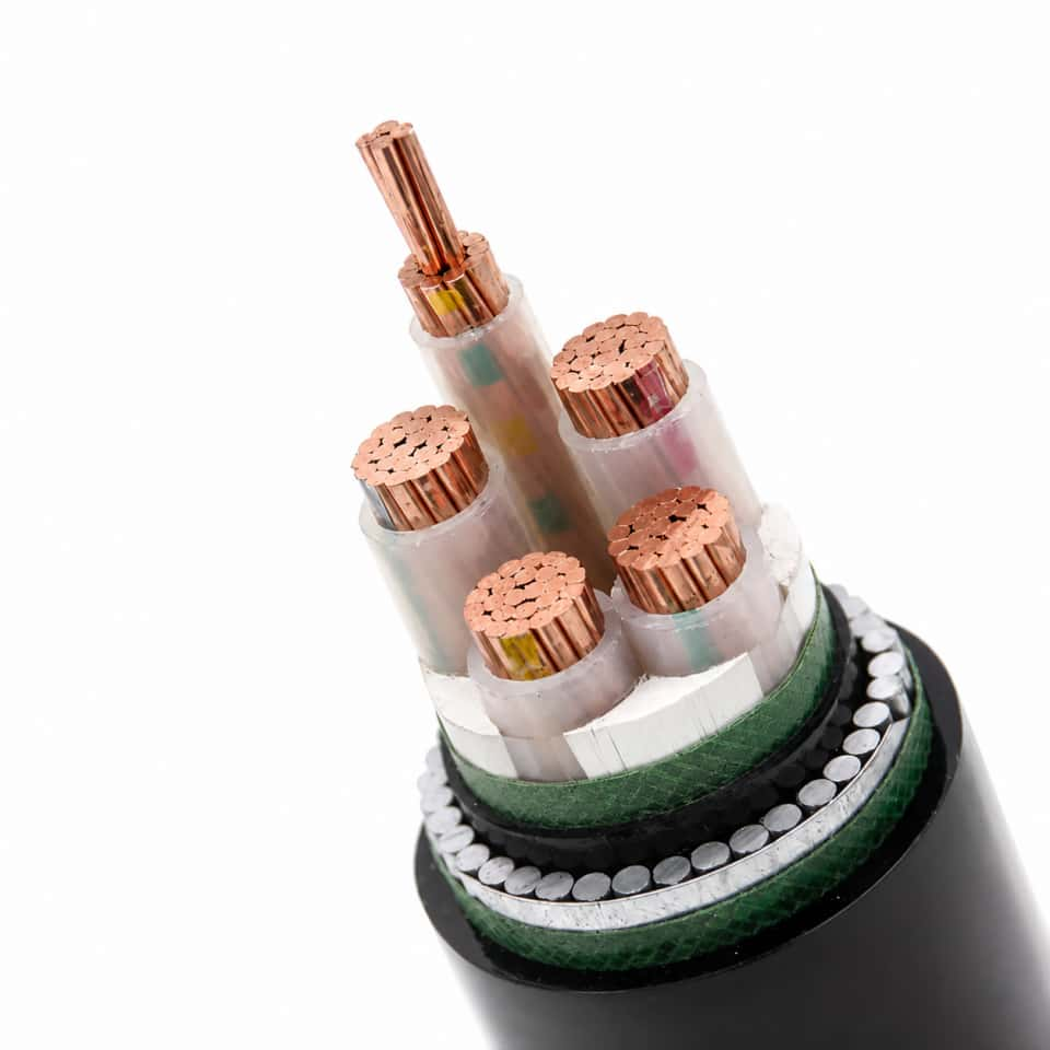
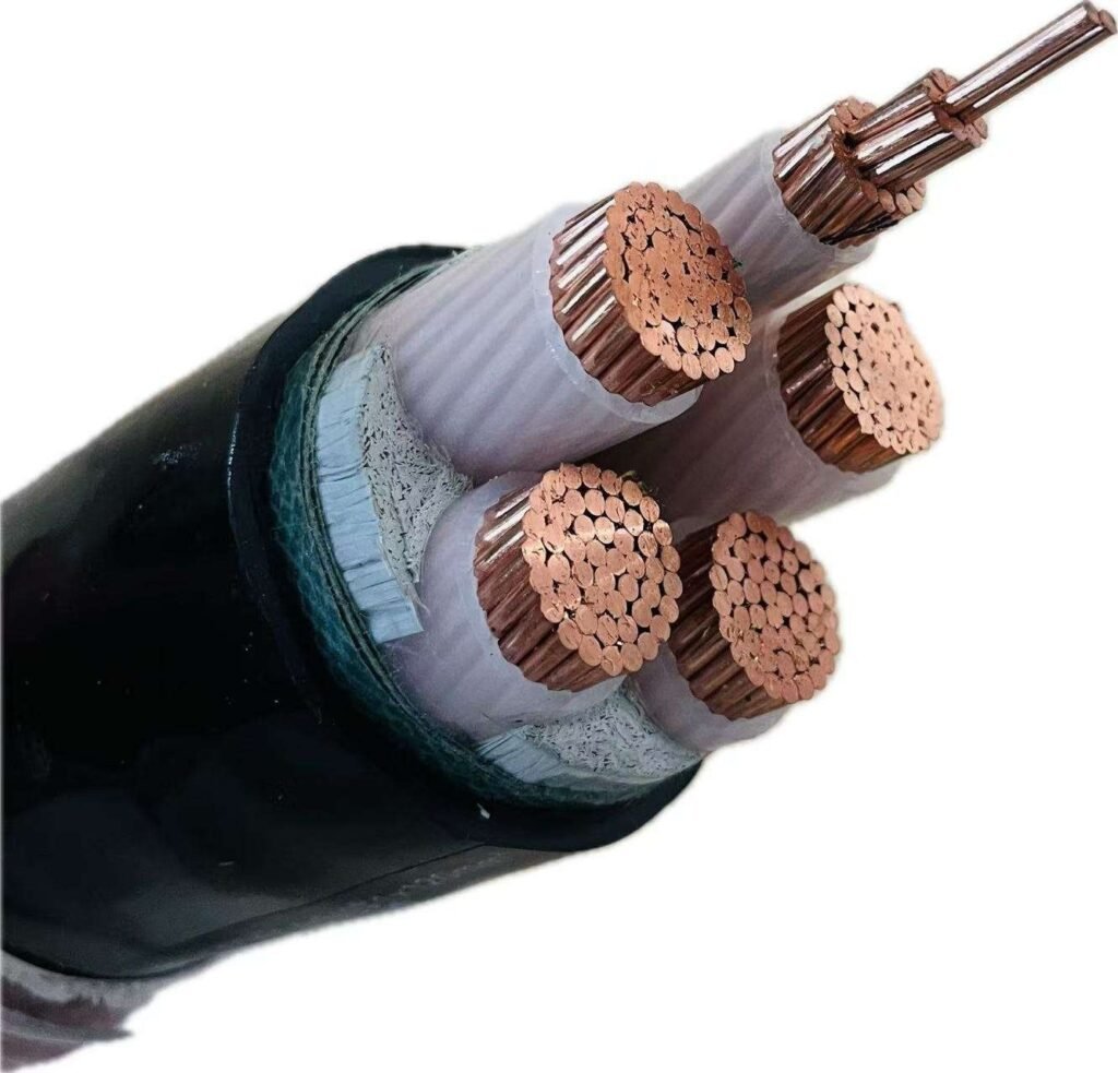
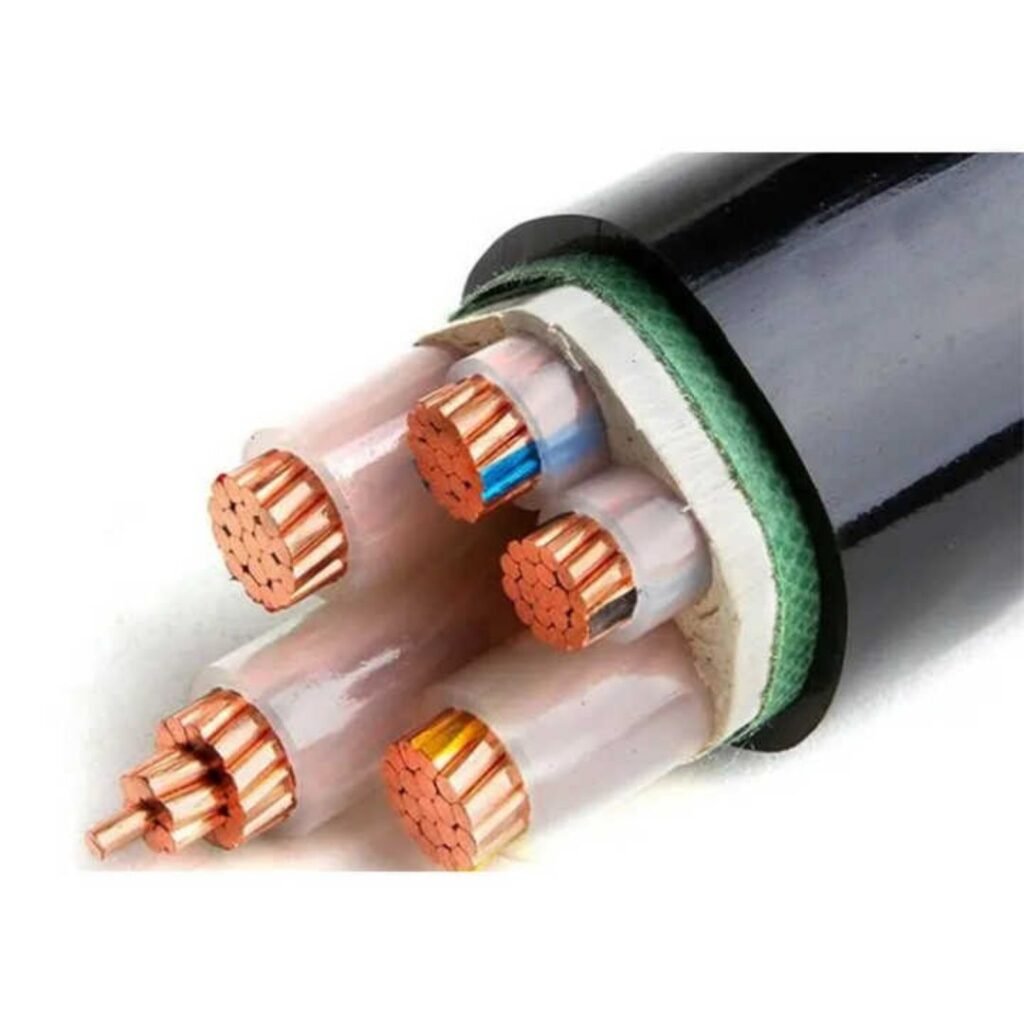
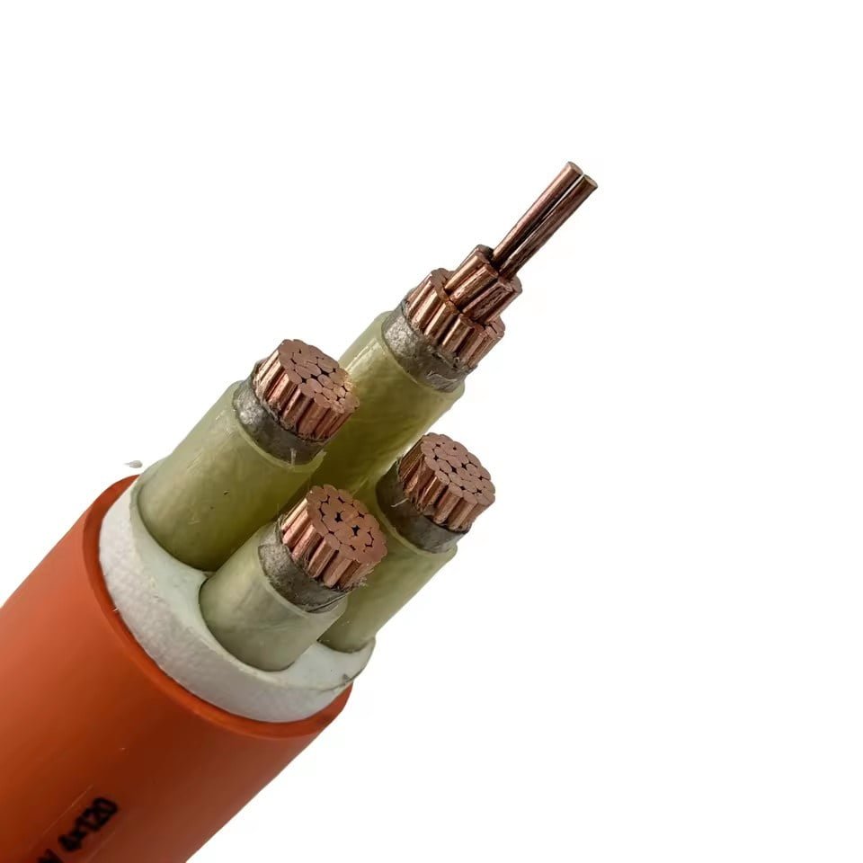
Choose the wrong power cable and the problem rarely appears neatly on day one; it shows up as nuisance trips, warm trays, sagging motor starts, premature insulation ageing, or an inspector holding the job at handover. Then the cost is not just copper you overbought or undersized cable you must replace, but downtime, rework, missed commissioning dates, and arguments over who signed off the schedule. The right starting point is a disciplined cable selection check: load, voltage, installation method, environment, voltage drop, protection, and applicable code.
To tell what power cable you need, confirm the supply voltage, full-load current, cable route length, installation method, ambient temperature, conductor material, insulation type, voltage-drop limit, and protective device rating. For many building and industrial low-voltage circuits, 0.6/1 kV cable with XLPE insulation is common, but the final size must be calculated and verified against local standards.
The awkward part is that no single number on a nameplate answers the question. A 75 kW motor, a rooftop HVAC feeder, and a production-line panel may draw similar current, yet need different cable constructions because tray fill, heat, starting current, chemical exposure, bending radius, and procurement lead time all pull the decision in different directions. That is where cable selection becomes less like buying a commodity and more like removing risk from the installation before copper is ordered.
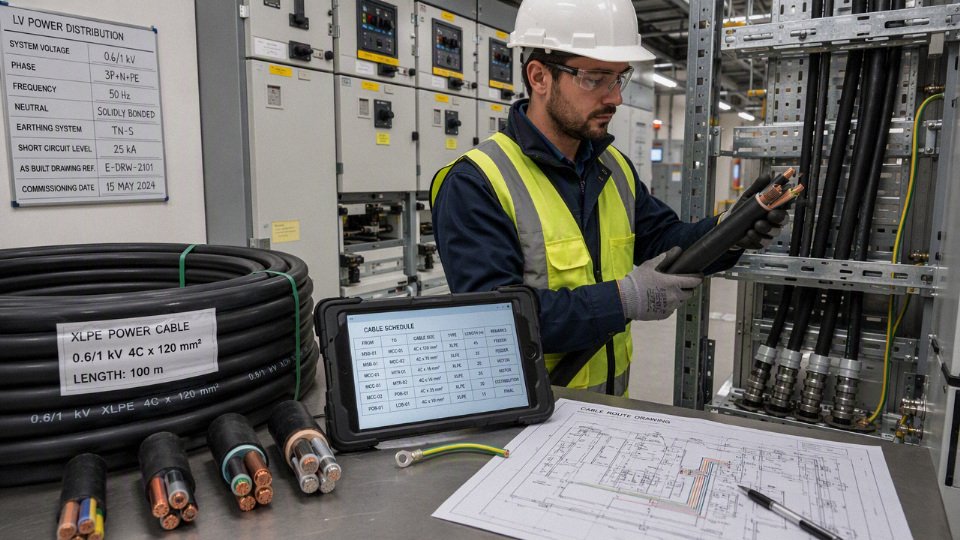
Load and circuit facts
Cable selection starts with the load, not the catalog. Before anyone chooses copper versus aluminum, XLPE versus PVC, or a 0.6/1 kV cable construction, engineering needs the circuit duty, current profile, voltage system, conductor count, route length, and installation conditions nailed down well enough that procurement is not buying “close enough” cable.
Identify the connected load
A motor feeder and a heater feeder can show the same running amperage on a load schedule and still need different treatment. The motor may draw several times rated current during acceleration, the heater is usually steady and resistive, and a variable frequency drive may bring harmonic current, reflected wave concerns, and screening or earthing requirements.
For a useful cable inquiry, classify the load first:
- Motor loads: pumps, conveyors, fans, compressors, mixers, crushers, and HVAC plant. Record motor power, full-load current, starting method, number of starts per hour, acceleration time, and whether the motor is DOL, star-delta, soft-starter, or VFD-fed.
- Transformers and UPS equipment: collect rated kVA, input and output voltage, inrush behavior, bypass arrangement, harmonic profile if known, and short-circuit contribution.
- Lighting panels and general distribution boards: note whether the downstream loads are mostly LED drivers, office loads, small motors, receptacles, or mixed plant loads.
- Heating loads: ovens, heat tracing, immersion heaters, dryers, and process heaters usually have high duty factors and may run near rated load for long periods.
- Welding equipment: check duty cycle, peak demand, diversity factor, and whether several welders can operate together. Nameplate current alone can mislead badly here.
- Cranes, hoists, and mobile machinery: capture acceleration, regenerative braking if used, pendant or radio control cabling, festoon/trailing cable needs, and mechanical movement.
- Shore power and temporary feeds: confirm plug standard, earthing arrangement, cable handling, exposure to oil, sunlight, water, and repeated coiling.
- Renewable energy systems and DC circuits: record DC voltage range, maximum current, polarity conductor count, insulation requirements, fault protection method, and environmental exposure.
- Service entry, submain, feeder, and branch circuits: define where the cable sits in the distribution hierarchy because protection, fault level, voltage drop allowance, and fire-performance requirements may change.
Separate normal current from abnormal and occasional current
Rated current is only one line in the story. A cable is thermally limited by the heat generated over time, but protective devices and voltage dip during starting are driven by much higher short-duration currents. If those are mixed up, the plant may either buy oversized cable everywhere or, worse, install a cable that survives normal running but nuisance-trips, overheats at terminals, or gives poor motor starting.
Ask engineering to provide these values separately:
| Current or load value | What it means in practice | Why it matters for cable selection |
|---|---|---|
| Rated or full-load current | Normal running current at rated output | Base input for ampacity and voltage drop checks |
| Starting current | Motor or equipment current during acceleration | Affects voltage dip, protection coordination, and terminal heating under repeated starts |
| Locked-rotor current | Motor current if the rotor cannot turn | Needed for fault/protection review; not a continuous cable sizing value |
| Inrush current | Transformer, UPS, LED driver, or power electronics magnetizing/charging surge | Can trip breakers or stress contacts without being a cable heating problem |
| Duty cycle | Percentage of time the load runs under a stated cycle | Intermittent loads may permit different thermal assumptions if allowed by code and design standard |
| Overload allowance | Planned short-term operation above rated load | Must be coordinated with cable temperature rating and protection settings |
| Future expansion load | Spare capacity for added machines or panels | Prevents replacing a buried or tray-installed feeder two years later |
The mechanism is simple but often missed: conductor losses rise roughly with the square of current, so a modest current increase creates a larger heat increase. Cable temperature then depends on how fast that heat escapes through insulation, bedding, armor, tray air, conduit, soil, or surrounding cables. A cable clipped in free air behaves very differently from the same cable buried in warm soil beside five other loaded circuits.
There is a trade-off. Designing every feeder for every possible future load wastes metal, tray space, and capital. Designing with no spare capacity can lock the plant into expensive shutdown work later. The preferred choice flips when the route is hard to replace: underground ducts, long tray runs above operating lines, marine shore feeds, and service entrances deserve more conservative planning than a short visible branch circuit to a replaceable skid.
Confirm voltage, phase, system earthing, and circuit duty
The buying description should not say only “power cable.” It should identify the electrical system clearly:
- Single-phase AC: line-neutral or line-line voltage, neutral loading, earthing method, and whether loads are balanced across panels.
- Three-phase AC: phase-to-phase voltage, phase-to-earth voltage where relevant, neutral requirement, motor starting method, and short-circuit level.
- DC circuits: nominal DC voltage, maximum operating voltage, polarity conductors, grounding method, ripple, switching behavior, and fault-clearing arrangement.
- Maximum system voltage: not just nominal voltage. A cable rated for common low-voltage building and industrial use, such as 0.6/1 kV, may be suitable in many LV systems, but the exact rating must match the governing standard and project specification.
- Earthing system: TN-S, TN-C-S, TT, IT, resistance-grounded, or other project-specific system. This affects protective earth sizing, screens, armor bonding, fault paths, and disconnection times.
- Circuit position: service entry, main feeder, submain, branch circuit, motor circuit, VFD output, emergency feeder, or control-power circuit.
Continuous-load rules deserve special care. Many codes require circuits that operate for long periods near full load to be sized with extra margin, often through an 80% breaker loading rule or a 125% continuous-load calculation, depending on the code framework and equipment listing. Do not apply a remembered rule blindly across IEC, NEC, local utility, marine, mining, or renewable-energy projects. The current equipment manual, local code, and project specification must decide the calculation method.
A neutral conductor is not automatically smaller than the phase conductor.True
Nonlinear loads, triplen harmonics, phase imbalance, and single-phase distribution can make the neutral carry substantial current. Some projects require a full-size or even oversized neutral, subject to the applicable code and harmonic study.
The neutral issue causes plenty of site arguments. In an old motor control center feeding balanced three-phase motors, a reduced neutral may be reasonable or no neutral may be needed. In an office, data room, retail facility, LED-heavy building, UPS output, or mixed single-phase distribution board, the neutral can run hot even when phase currents look acceptable. Triplen harmonics from nonlinear single-phase loads add in the neutral rather than canceling, so the “three phases balance out” assumption can be unsafe.
Define conductor count before asking for price
Conductor count is not just “3-core or 4-core.” The cable may need power cores, earthing conductors, screens, armor, bonding conductors, and small control cores. If procurement misses one of these, the lowest quote may be unusable.
Specify, as applicable:
- Phase conductors: one, two, or three depending on the AC system; positive and negative for DC.
- Neutral conductor: full-size, reduced, oversized, or omitted only when engineering confirms it.
- Protective earth conductor: separate core, separate green-yellow conductor, armor used as CPC where permitted, or both armor and separate PE.
- Concentric conductor: used in some distribution and service cables for neutral, earth, or combined functions depending on local practice.
- Metallic screen or shield: common for VFD motor cables, medium-voltage cables, instrumentation separation needs, and EMC-sensitive installations.
- Armor bonding conductor: sometimes needed where armor continuity, fault current return, or bonding reliability cannot be assumed from glands alone.
- Pilot cores: used for protection, interlocking, earth continuity monitoring, or control in mining, mobile equipment, and some industrial feeders.
- Control cores bundled with power cores: convenient for skids and small machines, but check voltage segregation, interference, termination space, and code acceptance.
Bundling controls with power can save installation labor and reduce tray congestion. The sacrifice is flexibility: if a control function changes, or if noise from a VFD output couples into a small signal, the whole cable choice may be wrong. In practice, I prefer bundled control cores only when the signals are simple, the route is short, and the equipment supplier has confirmed the arrangement.
What procurement should request from engineering
Before issuing an RFQ or approving an alternate cable, procurement should ask for a controlled set of documents rather than a few emails and a nameplate photo. At minimum, request:
- Load schedule showing connected load, demand load, continuous load, spare capacity, and duty cycle.
- Single-line diagram showing source, protection, earthing arrangement, transformer data, and downstream panels.
- Cable schedule listing cable tag, from-to points, voltage, conductor count, conductor size if already designed, insulation/sheath type, armor or screen, fire performance if required, and installation method.
- Installation route length including vertical drops, tray diversions, gland tails, and a realistic spare allowance. A 92 m measured route can become a 105 m purchased length very easily once tray risers and termination slack are included.
- Ambient and installation conditions: air temperature, grouping, tray or conduit fill, buried depth, soil thermal resistivity if buried, sunlight, wet areas, oil exposure, chemical exposure, mechanical impact, and movement.
- Governing standard and project specification: local electrical code, IEC/NEC basis, utility rules, client specifications, marine or mining rules if applicable, and required test certificates or documentation.
- Voltage drop requirement: many projects use practical targets around 3% for branch circuits and 5% total feeder plus branch, but the enforceable value comes from code, client specification, and equipment tolerance.
- Protection data: breaker or fuse type, rating, trip setting, fault level, required disconnection time, and any selectivity study constraints.
This section’s conclusion stops holding when the project is still conceptual and the load list is not stable. At that stage, procurement can price budgetary cable families and metal escalation exposure, but it should not freeze conductor size or construction. Once routes, duty, protection, and standards are defined, the cable decision becomes an engineering selection rather than a purchasing guess.
Voltage class and insulation
Cable voltage rating and insulation choice should match the circuit’s electrical stress, operating temperature, and environment, not just the nameplate voltage of the machine. For most building and industrial low-voltage distribution, ratings such as 300/500 V, 450/750 V, and 0.6/1 kV cover different installation duties; once the system moves above low-voltage distribution, medium-voltage cable design becomes a different engineering exercise.
Nominal system voltage is the voltage you operate at: for example, 230/400 V, 277/480 V, or 600 V systems depending on the country and plant standard. Cable rated voltage is the maximum voltage stress the insulation system is designed and tested to withstand under defined conditions. That difference matters on messy plant floors where motors are started across the line, variable-frequency drives create waveform stress, grounding systems are not always ideal, and old panels sometimes carry more transient noise than the single-line diagram suggests.
Common low-voltage classes are usually applied like this:
| Cable voltage class | Typical use | Practical caution |
|---|---|---|
| 300/500 V | Light-duty control, small appliances, some indoor wiring depending on local rules | Not a default choice for industrial feeders or outdoor plant wiring |
| 450/750 V | Building wire, control power, lighting, equipment wiring in many markets | Check installation method and mechanical protection, not voltage only |
| 0.6/1 kV | Common building and industrial low-voltage power cable rating | Often preferred for feeders, plant distribution, outdoor runs, and heavier-duty service |
| Medium voltage, above low-voltage distribution levels | Utility intake, large motors, substations, mining, heavy industry | Requires shielded insulation systems, stress control, terminations, testing, and standards specific to MV cable |
The “0.6/1 kV” notation means 0.6 kV conductor-to-earth and 1 kV conductor-to-conductor under the relevant cable standard. It does not mean the cable can be casually used on any 1 kV process without checking the governing standard, earthing arrangement, overvoltage category, and fault clearing design. In procurement, I prefer to see the voltage class written explicitly instead of buried in a model code, because substitutions often happen during bid clarification.
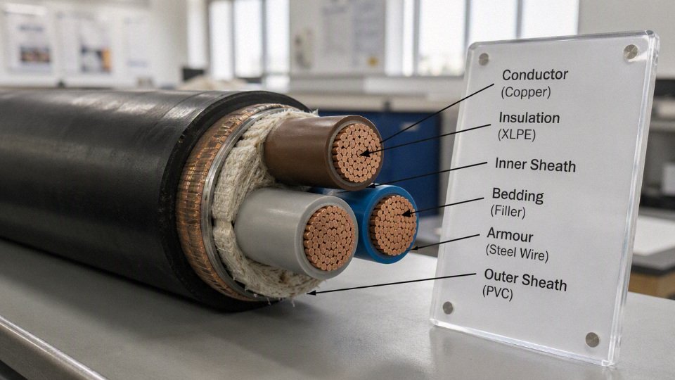
Insulation is the layer that keeps the conductor electrically separated from other conductors, metallic screens, armor, trays, wet concrete, and human hands. Its first job is dielectric strength, but that is only the start. A good insulation choice also has to survive heat, moisture, aging, bending, pulling tension, compression at cleats, conductor strand movement, and chemical interaction with the sheath and any tapes or fillers.
The mechanism is straightforward but unforgiving: higher current raises conductor temperature; temperature accelerates insulation aging; aged insulation loses mechanical and dielectric margin; damaged insulation then fails under normal voltage or a switching surge that a new cable would have tolerated. That is why two cables with the same copper size can have very different service lives in the same tray if one is running hot in a packed ladder and the other has air around it.
Common insulation materials differ in useful ways:
- PVC insulation is widely used for general low-voltage building and light industrial cables. It is economical, easy to process, and familiar to installers. Standard PVC insulation is often associated with 70 C conductor temperature ratings, although the exact rating depends on the cable standard and compound.
- XLPE insulation is a strong default for many industrial power cables where higher thermal performance is needed. Typical XLPE insulation is commonly rated for 90 C continuous conductor operation, subject to the applicable standard and cable design. It can support higher ampacity than 70 C insulation when the whole installation allows it.
- EPR insulation is valued where flexibility, wet service, and demanding industrial environments matter. It is common in mining, marine, trailing, and some medium-voltage constructions. It normally costs more than basic PVC or XLPE, but it can be the better engineering choice where repeated movement or moisture exposure would punish a stiffer cable.
- Rubber compounds are used for mobile duty, portable equipment, welding leads, cranes, temporary power, and workshop cables. The trade-off is usually price and, sometimes, dimensional bulk, but the handling benefit is obvious when a cable is dragged, coiled, or flexed daily.
- Mineral-insulated cable uses inorganic insulation, often magnesium oxide in a metallic sheath, for fire-survival and high-temperature applications. It is specialized, less forgiving to terminate, and not something to swap into a project late without installers who know the system.
A higher insulation temperature rating does not automatically make a cable safe at higher current. Terminals may be rated only 70 C. Glands, enclosures, molded-case breaker lugs, distribution boards, cable ties, trunking, and local installation standards may force you to calculate ampacity at a lower terminal temperature. I have seen perfectly good 90 C cable landed in old gear where the practical allowable current was set by the panel hardware, not by the cable catalog.
Sheath and jacket material should be specified separately from insulation. The sheath protects the cable from the outside world; it does not replace the insulation’s electrical function.
| Sheath or jacket material | Where it is commonly considered | Main selection issue |
|---|---|---|
| PVC | General indoor and outdoor low-voltage cables | Economical, but smoke, halogen, oil, and cold-bend limits must be checked |
| PE | Direct burial, moisture exposure, outdoor service | Good moisture resistance; flame behavior may need separate treatment |
| LSZH | Tunnels, public buildings, data centers, ships, enclosed occupied spaces | Lower smoke and halogen performance, but compound toughness and outdoor suitability vary |
| TPU | Dragging, abrasion, robotics, portable industrial equipment | Excellent wear resistance; cost and chemical compatibility need review |
| CPE and chlorinated compounds | Oil, weather, industrial chemical exposure, flexible power cables | Useful in harsh service; verify flame, oil, and temperature ratings against the project standard |
| Project-specific compounds | Cold stores, solar farms, petrochemical areas, rail, marine, mining | Selection depends on UV, oil, mud, salt, flame spread, rodents, low temperature, or specific chemical exposure |
The trade-off between PVC and XLPE is a common buying decision. PVC can be the right answer for dry, protected, low-voltage general wiring where cost and availability dominate. XLPE starts to win when continuous load is high, ambient temperature is elevated, circuits are grouped, or a smaller cable size is possible after proper derating. The preference flips back if the connected equipment, termination temperature, or installation code prevents use of the higher thermal rating.
For temperature ratings, treat the published number as one input to the ampacity calculation, not permission to run the cable hot. A 70 C PVC-insulated cable, a 90 C XLPE-insulated cable, and a higher-temperature special cable may all be physically capable of their rated conductor temperature, but the installation may not be. Grouped cables in a tray, ducts in sun-exposed concrete, poor ventilation above a furnace line, and high harmonic currents can move the actual conductor temperature well above what the buyer expected from a simple catalog comparison.
Short-circuit withstand is part of the same discussion. During a fault, the conductor and insulation see a brief but severe thermal event. If the protective device does not clear quickly enough, the insulation may be damaged even though the cable looked correctly sized for normal running current. This is especially relevant where old fuses are replaced with breakers, generator fault current is limited, or multiple feeders are paralleled.
A 90 C XLPE-insulated cable can always carry more current than a 70 C PVC-insulated cable of the same conductor size.False
The insulation rating may allow a higher calculated ampacity, but the usable current can be limited by terminal temperature, ambient conditions, grouping derating, installation method, voltage drop, and short-circuit withstand.
A practical specification should make the electrical and environmental intent clear enough that suppliers are not guessing. For the voltage and insulation part, write it in a structured line rather than a vague request for “industrial cable”:
- Conductor: copper or aluminum, class of stranding if flexibility matters.
- Rated voltage: for example, 450/750 V or 0.6/1 kV, according to the applicable standard.
- Insulation: PVC, XLPE, EPR, rubber, mineral insulation, or other defined material, with temperature rating where required.
- Sheath or jacket: PVC, PE, LSZH, TPU, CPE, chlorinated compound, or project-specific compound.
- Fire and smoke requirement: flame retardant, fire-resistant, LSZH, low smoke, or circuit integrity requirement, tied to the relevant project standard.
- Environmental exposure: indoor, outdoor, direct burial, tray, duct, oil, sunlight, salt mist, chemical splash, cold bend, rodent risk, or moving duty.
- Applicable standard: IEC, BS, EN, UL, ICEA, AS/NZS, or the local project standard, stated precisely in the purchase document.
A clean example would be: “Copper conductor, 0.6/1 kV, XLPE insulated, LSZH sheathed, flame-retardant low-smoke construction, suitable for fixed installation in cable tray, manufactured and tested to the stated project standard.” That kind of wording gives engineering, purchasing, and the cable manufacturer the same target. The remaining checks are ampacity derating, voltage drop, fault level, termination compatibility, and any local code requirement that overrides the catalog rating.
Ampacity and derating
Ampacity is the continuous current a cable can carry under stated installation conditions without exceeding the conductor and insulation temperature limit. The size printed in a catalog is only a starting point; the usable ampacity can fall sharply once ambient heat, grouping, conduit fill, burial conditions, and terminal limits are applied.
A 90 C XLPE-insulated cable, for example, is not automatically allowed to run every termination, breaker, gland plate, and enclosure at 90 C. In many low-voltage installations, the cable insulation may be rated higher than the equipment terminals, so the final allowable current has to respect both the cable table and the connected equipment. This is where a lot of wrong purchases happen: the cable cross-section looks generous on paper, but the installation route quietly removes the spare capacity.
Published cable ampacity is conditional, not universal.True
Ampacity tables are based on a specific standard, reference installation method, ambient temperature, conductor material, insulation temperature rating, and heat dissipation condition. Changing the route from open air to conduit, grouping cables tightly, or burying them in poor soil can change the allowable current substantially.
What actually determines ampacity?
Ampacity is a heat balance problem. Current creates losses in the conductor; the installation either removes that heat effectively or traps it around the cable. Once the conductor temperature rises above its allowable limit, insulation aging accelerates, terminations loosen or oxidize faster, and nuisance trips may become the least expensive symptom.
The main variables are:
- Conductor cross-sectional area: larger conductors have lower resistance, so they generate less heat at the same current.
- Conductor material: copper has higher conductivity than aluminum, so it usually carries the same current in a smaller cross-section.
- Insulation temperature rating: common XLPE insulation may be rated for 90 C continuous operation, but the whole circuit must still be checked against equipment terminal ratings and the applicable code.
- Installation method: a single cable clipped in open air cools very differently from the same cable in a packed steel conduit.
- Ambient temperature: a cable in a 45 C roof void or near a furnace has less thermal headroom than one in a 25 or 30 C equipment room.
- Soil thermal resistivity: buried cable capacity depends heavily on how well the soil conducts heat. Dry sand, ash fill, or disturbed backfill can be much worse than moist compacted soil.
- Burial depth: deeper burial can reduce temperature swings, but it may also reduce heat dissipation depending on soil and route conditions.
- Grouping and spacing: loaded circuits beside each other heat one another; spacing is not cosmetic, it is part of the rating.
- Ducts, trays, and conduit fill: the same copper or aluminum conductor can have different ampacity in perforated tray, ladder rack, trunking, underground duct, or rigid conduit.
- Ventilation: forced or natural air movement around trays and risers matters, especially in cable basements, tunnels, MCC rooms, and enclosed service corridors.
- Wet, submerged, or chemically exposed locations: ampacity is only one issue there; sheath material, water blocking, corrosion resistance, and gland sealing also become part of the selection.
The mechanism is simple enough, but the plant-floor result is not always obvious. A cable may pass the electrical load calculation and still run hot because it is routed above a steam line, bundled through a crowded tray drop, or pulled through an old conduit that already carries several loaded circuits. I have seen maintenance teams blame the breaker first, then the motor, when the real problem was a tray section packed so tightly that no air could move through it.
Basic sizing sequence
Use ampacity after the load is known, not before. The normal engineering sequence is:
- Calculate the design current
- Use the actual load profile, duty cycle, motor starting behavior, harmonic content where relevant, and future allowance if the project specification requires it.
- Do not size a feeder from nameplate totals alone if the plant has a defined demand factor or process diversity.
- Select the protective device
- Choose the breaker or fuse rating based on load type, starting current, overload protection needs, and local code rules.
- The cable must be protected against overload and short-circuit damage, not just sized for normal running current.
- Choose an initial conductor size from an ampacity table
- Match the table to the cable type, conductor material, insulation class, voltage class, and reference installation method.
- Common industrial low-voltage power cables may be rated 0.6/1 kV, but voltage class does not replace ampacity sizing.
- Apply correction or derating factors
- Adjust for ambient temperature, grouping, installation method, soil conditions, ducts, tray fill, ventilation, and other conditions defined by the standard or project specification.
- Some standards apply correction factors sequentially; some tables already include certain assumptions. Mixing methods is a good way to oversize one circuit and undersize the next.
- Verify corrected ampacity
- The corrected cable ampacity should be equal to or greater than the design current and suitable for the selected protective device.
- If the protective device is larger than the corrected cable capacity, the coordination needs to be fixed.
- Confirm terminal and installation compatibility
- Check lug material, terminal temperature rating, gland size, bending radius, pulling tension, short-circuit rating, and enclosure space.
- For aluminum conductors, confirm that lugs are aluminum-rated or bimetallic as required, and that the installer uses the correct joint compound and torque practice.
- Check voltage drop and starting performance
- Ampacity prevents overheating; it does not guarantee acceptable voltage at the load.
- Practical voltage drop targets are often around 3% for branch circuits and 5% total feeder plus branch circuit, subject to local code and the project specification.
A cable selected only by nominal ampacity is not fully selected. It still has to survive the route, the protection scheme, the terminals, the voltage drop requirement, and the way the site will actually install it at 4 p.m. on a Friday.
Installation method changes the answer
Open air is usually the most forgiving condition because heat can leave the cable surface easily. Ladder rack and well-ventilated cable tray can also perform well, provided spacing and fill are controlled. A neat tray with single-layer power cables and some air gap is a different installation from a tray carrying a deep pile of mixed feeders, VFD output cables, and small control cables buried underneath.
Conduit and trunking restrict heat flow. They also create practical limits: pulling tension rises, bends become harder, and conduit fill can make future maintenance miserable. In a hot production area, a conduit run on the sunny side of a wall or above process ovens can punish the cable far more than the drawing suggests.
Underground duct banks are a separate calculation, not just “cable in pipe.” Heat must pass from the conductor through insulation, sheath, air or filler in the duct, duct wall, concrete encasement if present, and soil. Soil thermal resistivity and mutual heating between ducts can dominate the result. Direct burial may cool better than duct in some conditions, but it gives up accessibility and increases the importance of mechanical protection, route marking, water resistance, and repair planning.
Building voids and thermal insulation are common traps. A cable above a ceiling tile may be in warm stagnant air; a cable covered by insulation can lose much of its heat dissipation path. In practice, this is where “same load, same cable size” stops being true. The route through the building can be the sizing condition, not the load.
Wet, submerged, or intermittently flooded locations need separate attention. Water can improve heat transfer in some cases, but that does not make any ordinary cable suitable for the location. Jacket compound, water ingress resistance, armor corrosion, gland sealing, and mechanical damage risk have to be checked against the supplier documentation and the site exposure.
Why grouping derating gets expensive fast
Grouping is one of the most underestimated derating factors because every individual cable may look correctly sized. The problem appears when several loaded circuits share the same tray, conduit, duct bank, or riser. Each cable is trying to reject heat into air or soil that has already been warmed by its neighbors.
The effect is not linear in a way buyers can safely guess from the cable count. A few spaced cables on a ladder rack may be acceptable with modest correction. A tightly bundled tray, a crowded PVC conduit, or a duct bank with several high-duty feeders can reduce the usable ampacity dramatically compared with a single cable in free air. The exact factor depends on the standard being used, the number of loaded conductors, spacing, arrangement, ambient conditions, and whether the circuits are continuously loaded.
There is a commercial trade-off here. Running larger cables through the same congested route may seem cheaper than adding tray, duct, or separation, especially when civil work is painful. But larger conductors are stiffer, harder to terminate, heavier on supports, and more expensive in copper or aluminum. At some point, improving the route is cheaper and safer than throwing cross-section at a thermal problem.
A counter-intuitive point is worth saying plainly: a larger cable can still overheat if the derating basis is wrong. Upsizing reduces conductor losses, but it does not cancel poor ventilation, high ambient temperature, or mutual heating. If the original route assumption was “single circuit in open air” and the actual site condition is “multiple circuits in enclosed trunking through a hot mezzanine,” the calculation has changed, not just the safety margin.
Copper or aluminum under derated conditions
Copper is usually selected where space is tight, terminations are compact, bending routes are difficult, or downtime from joint problems would be costly. It gives higher conductivity in a smaller conductor, which helps in crowded panels and shorter gland plates. The trade-off is purchase cost and, on large feeders, weight can still be significant.
Aluminum can be commercially attractive for long feeders, large cross-sections, and projects where weight reduction matters. It normally needs a larger cross-sectional area for the same current, so the saving is not a simple price-per-meter comparison. Larger outside diameter can affect tray fill, conduit size, bending radius, pulling equipment, gland selection, and panel entry layout.
Aluminum also demands better termination discipline. Oxide control, compatible lugs, correct crimp dies, joint compound where specified, torque marking, and retorque policy all matter. Creep and thermal cycling are not academic issues on a feeder that starts and stops heavy loads every shift. A good aluminum installation is reliable; a casual one becomes a hot joint inspection program.
The choice can flip with the route. If tray space and panel entries are generous, aluminum may be the best procurement decision. If the job is a retrofit through existing conduit with limited bending space and crowded switchgear, copper may save enough installation pain to justify the higher material cost.
Published tables need the right reference conditions
Ampacity tables are only as good as the match between their assumptions and the job. One table may assume a specific ambient air temperature, a defined soil thermal resistivity, a certain number of loaded conductors, a reference installation method, and a particular insulation temperature rating. Another standard may classify the same route differently.
Before approving a cable size, check:
- Which standard or code the project follows.
- The reference installation method used in the ampacity table.
- Ambient temperature assumptions for air installations.
- Soil thermal resistivity and burial assumptions for underground routes.
- Number of loaded conductors and grouping arrangement.
- Tray, conduit, trunking, or duct fill limits.
- Terminal temperature ratings at breakers, switches, busbars, and equipment.
- Whether the load is continuous, cyclic, intermittent, or spare capacity for future expansion.
- Short-circuit withstand requirements, which may push conductor size beyond normal ampacity.
- Voltage drop and motor starting voltage, which often require a larger cable than thermal ampacity alone.
The practical boundary is this: ampacity selection is reliable only when the route and duty assumptions are reliable. If the cable schedule is being priced before tray layout, duct bank design, ambient conditions, and grouping are known, the quotation should state the assumptions clearly rather than pretending the size is final.
Voltage drop and starting
A cable can pass the ampacity check and still be too small if the route is long or the connected equipment pulls high starting current. Voltage drop is the voltage lost along the cable because the conductor has resistance, and on larger AC circuits, reactance as well. In practice, this is where modest loads on long runs often force the buyer into the next conductor size.
Voltage drop is not a nameplate issue; it is a circuit behavior issue. Current flowing through copper or aluminum produces a voltage loss proportional to the conductor impedance and the load current. As the cable heats up, conductor resistance rises, so the same cable may drop more voltage in a hot cable tray in August than it did during commissioning on a cool morning.
That lost voltage shows up at the equipment terminals. A motor that should see roughly rated voltage may start sluggishly, pull higher current for longer, and run hotter. Lighting may dim. Contactors and control relays may chatter or drop out. Battery chargers and EV charging equipment may underperform because the input voltage falls below the range where the electronics can deliver full output. VFDs may trip on undervoltage during acceleration, especially if the supply is already weak or several machines start close together.
Common design targets are often around 3% voltage drop for branch circuits and 5% total for feeder plus branch circuit, where those values are accepted by the applicable code and project specification. They are not universal permissions. Local electrical code, utility connection rules, fire and mining regulations, marine or port requirements, and the equipment manufacturer’s voltage tolerance take priority.
A cable sized only by ampacity may still be undersized for a long circuit.True
Ampacity checks thermal current-carrying capability, while voltage drop depends on route length, conductor impedance, load current, power factor, and allowable terminal voltage. Long runs can fail the voltage-drop requirement before they reach the cable's thermal limit.
For a useful voltage-drop calculation, the engineer or supplier needs more than “50 A load, 100 m cable.” The basic inputs are:
- One-way circuit length: measured along the actual cable route, not straight-line distance on a site drawing. A farm pump route that snakes around a road and a drainage channel is not the same as the map distance.
- Load current: design running current, not only breaker size. For motors, use the expected operating current and check against full-load current.
- Phase arrangement: single-phase, three-phase, DC, or mixed supply. The voltage-drop formula and return path differ.
- Conductor material: copper and aluminum have different resistance, and aluminum usually needs a larger cross-section for the same drop.
- Conductor size and construction: cross-sectional area, number of cores, installation grouping, and whether conductors are paralleled.
- Power factor: low power factor increases the reactive component of voltage drop on AC systems.
- Cable reactance: often small on short low-voltage runs, but it matters on larger conductors, long feeders, and motor circuits.
- Operating temperature: resistance rises as conductor temperature rises. A cable near its thermal limit will not perform like the catalog value at reference temperature.
- Allowable voltage drop: set by code, equipment tolerance, process needs, and any owner specification.
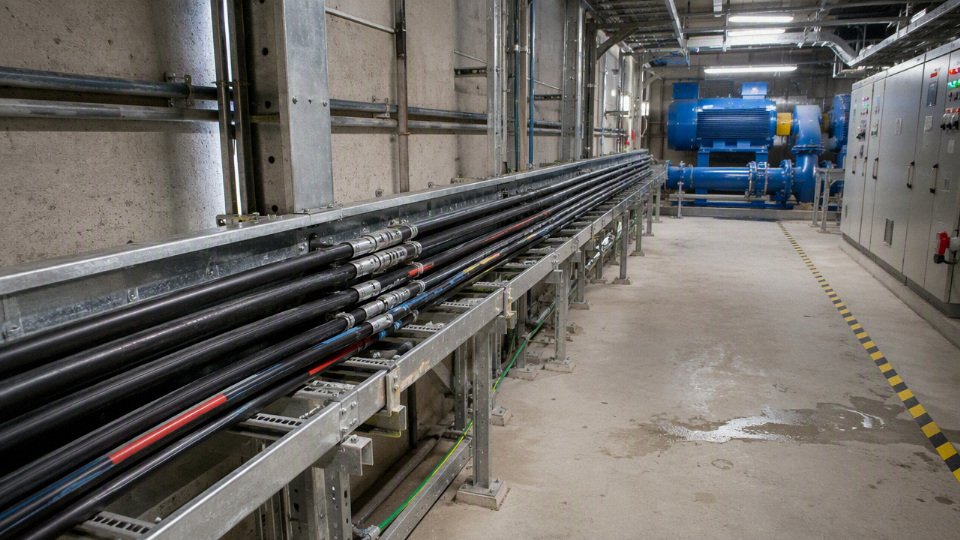
The mechanism is simple but unforgiving. During steady running, voltage drop follows the continuous load current and cable impedance. During motor starting, the current may jump several times above running current for a short period, and the voltage dip at the motor terminals can be much deeper than the steady-state calculation suggests. A pump with low starting torque demand may tolerate this. A loaded conveyor, crusher, compressor, mixer, or high-inertia fan may not.
That distinction matters in procurement. A buyer may look at a 37 kW motor and ask for the cable size based on normal current. The maintenance electrician is thinking about the loaded restart after a short power interruption, with wet material sitting on the belt and the supply transformer already carrying other plant loads. Both are looking at the same motor, but only one is considering the worst operating event.
Motor-starting voltage dip is affected by:
- Starting method: direct-on-line starting causes a larger dip than soft starters or VFD-controlled starts, though VFDs introduce their own harmonic, EMC, and protection considerations.
- Load inertia: crushers, compressors, long conveyors, and pumps with heavy rotating mass stay in the high-current acceleration region longer.
- Supply stiffness: a strong transformer close to the load behaves differently from a rural feeder or temporary generator supply.
- Cable length and size: longer, smaller conductors add impedance and deepen the voltage dip.
- Simultaneous starts: two motors starting together can turn an acceptable design into a nuisance-trip problem.
Long-run sites are where voltage drop stops being a textbook note and starts controlling the bill of materials. Mines, farms, ports, tunnels, solar plants, water treatment sites, quarries, irrigation systems, and wide industrial campuses can have hundreds of meters between the distribution point and the load. On those projects, I would rather see the route length marked on a cable schedule than buried in a civil drawing set. A small mistake there can mean buying a cable that is thermally legal but operationally poor.
Oversizing for voltage drop is not waste when the equipment needs terminal voltage to start and run correctly. The trade-off is capital cost, pulling weight, bending radius, gland size, termination space, and sometimes longer delivery time. The preferred choice flips when the route is short, the supply is stiff, the load is tolerant, or the equipment has controlled starting; then ampacity, installation method, and protection coordination may dominate again.
The boundary is worth stating clearly: voltage-drop sizing only makes sense after the load data and route are reasonably fixed. If the plant later moves the MCC, changes from soft start to direct-on-line, substitutes aluminum for copper, or adds another motor on the same feeder, the calculation has to be checked again. On a long cable run, those changes are not paperwork details; they can decide whether the equipment starts on Monday morning.
Environment and cable construction
A cable that is electrically large enough can still fail early if its construction does not match the site. In harsh service, sheath material, armor, flexibility, screening, and fire behavior often decide cable life more than one extra conductor size. Treat the route as a mechanical, chemical, thermal, and fire-safety environment first, then finalize the electrical details inside that boundary.
For demanding industrial and public-building installations, the outer sheath and mechanical construction are often more critical to service life than a small increase in conductor cross-section.True
Conductor size mainly addresses ampacity and voltage drop. Many premature cable failures in harsh routes start at the jacket or protection system through cracking, abrasion, water ingress, chemical attack, crushing, or rodent damage. The exact priority still depends on the load, installation method, and applicable standard.
Classify the route by exposure before choosing the cable
Do not describe a cable route as only “indoor” or “outdoor.” That is too loose for procurement. A cable running 20 m through a dry MCC room, then across a washdown area, then outside on a tray in sunlight is three environments, not one.
Use a route schedule and mark each section by exposure:
| Route condition | Construction issue that usually matters | Procurement note |
|---|---|---|
| Indoor dry | Basic insulation, sheath toughness, tray or conduit protection | Unarmored cable may be fine if the route is protected and local code permits |
| Indoor wet or washdown | Water-resistant sheath, sealed glands, corrosion-resistant supports | Watch terminations; water often enters at poor glands, not through the cable wall |
| Outdoor sunlight | UV-resistant sheath, thermal rating, weathering resistance | Black UV-stabilized sheaths are common, but verify the stated standard or test basis |
| Underground direct burial | Armor, moisture barrier, sheath abrasion resistance, termite or rodent risk | Bedding, warning tape, depth, and pulling damage matter as much as cable type |
| Underground in duct | Pulling tension, sidewall pressure, water accumulation in duct | Ducts are rarely dry for long; assume standing water unless proven otherwise |
| Submerged or flood-prone | Water-blocking, sheath integrity, suitable glands and joints | Standard outdoor cable is not automatically submersible |
| Marine or coastal | Salt spray, corrosion, vibration, oil or fuel exposure | Aluminum components, galvanized armor, glands, and tray materials need compatibility checks |
| Corrosive industrial area | Acid, alkali, solvent, fumes, and chemical splash resistance | Match sheath compound to the actual chemical, concentration, and temperature |
| Oily workshop | Oil-resistant sheath, flexible construction if on moving machinery | PVC, rubber, CPE, PUR, or other compounds behave differently in oil and coolant |
| High-temperature area | Insulation thermal class, sheath aging, distance from heat source | Ambient heat plus cable grouping can age the jacket faster than expected |
| Low-temperature area | Low-temperature bending and impact performance | A cable that is fine after installation may crack if handled cold |
| Moving equipment | Fine-wire conductors, flexible sheath, controlled bend radius | Standard stranded building cable is not a festoon or drag-chain cable |
| Fire-risk zone | Flame spread, smoke, halogen, toxicity, circuit integrity | Specify the fire performance class, not just “fire cable” |
| Public escape route | Low smoke, halogen-free, low toxicity, flame control | Hospitals, airports, rail stations, tunnels, data centers, and high-occupancy buildings may have project-specific requirements |
The mechanism is simple but unforgiving: the environment attacks the weakest layer first. UV hardens some jacket compounds, oil swells others, water migrates along poor terminations, and thermal cycling opens tiny paths at glands and bends. Once moisture or contaminants reach the insulation screen, conductor, or armor, the failure no longer looks like a sheath problem on the maintenance report; it shows up as insulation resistance decline, nuisance trips, corrosion, or a fault during a wet week.
Match mechanical protection to the installation, not habit
Unarmored cable is acceptable in many protected routes: cable tray inside an electrical room, conduit runs, risers with no impact risk, or equipment wiring inside guarded areas. It is cheaper, lighter, easier to terminate, and usually faster to pull.
Armored and protected constructions earn their cost where the cable can be hit, crushed, pulled across rough ground, attacked by rodents, or buried. Common options include:
- Steel wire armor: good all-around mechanical protection and tensile strength, often used for multicore power cables in industrial and underground service.
- Steel tape armor: useful against crushing and impact in some buried or fixed installations, but less suitable where high tensile pulling loads are expected.
- Aluminum wire armor: commonly considered for single-core AC cables where ferromagnetic steel armor can cause heating from magnetic effects. The full system design still needs verification, especially bonding and fault-current duties.
- Metallic braid: gives flexible mechanical protection and can help with screening or grounding, depending on design, but it is not the same as heavy armor.
- Flexible armored constructions: useful for machinery and frequent handling, provided the bend radius and torsion limits match the movement.
- Conduit, tray, and duct systems: sometimes better than buying a heavier cable. A properly designed tray or duct bank can control route damage, support spacing, segregation, and future replacement.
The trade-off is weight, installation effort, and termination complexity. Armor improves survival, but it increases cable diameter, pulling force, gland cost, bending radius, and labor time. The preferred choice flips when the route is accessible, protected, and easy to inspect; in that case, a simpler cable in a good tray can be more maintainable than an over-armored cable jammed through undersized bends.
Choose conductor form for installation and movement
Conductor class is not a cosmetic detail. It changes how the cable pulls, bends, terminates, and survives vibration.
- Solid conductors: simple and economical in smaller sizes, but stiff. They are poor choices for vibration or repeated movement.
- Stranded conductors: the normal industrial workhorse for easier handling and better bending than solid conductors.
- Compacted stranded conductors: reduce conductor diameter and can make the finished cable smaller, but they may require compatible lugs and correct crimp tooling.
- Flexible class conductors: better for tight routing, panel wiring, machinery connections, and locations where vibration is present.
- Fine-wire conductors for portable equipment: suited to trailing leads, welding-type service, temporary power, hoists, and moving equipment, provided the insulation and sheath are also designed for that duty.
Flexibility is gained by using more, smaller strands, but that creates termination discipline. Fine strands can be damaged by poor stripping, squeezed out of cheap lugs, or loosen under thermal cycling if the lug, ferrule, or crimp die is wrong. In practice, I want the cable supplier and lug supplier aligned before bulk purchase, especially on flexible conductors above modest sizes; the wrong crimp system will turn a good cable into a hot joint.
Use shielding where interference or fault control matters
Screened or shielded cable is not only for instrumentation. It is commonly specified for medium-voltage circuits, VFD motor leads, power routes near sensitive control or measurement wiring, and installations where electromagnetic interference must be reduced.
For VFD-fed motors, fast switching edges can produce common-mode currents, bearing stress, reflected-wave issues, and electrical noise in nearby circuits. A suitable screened motor cable with proper 360-degree gland termination gives those high-frequency currents a lower-impedance return path than random tray steel, conduit joints, or PLC signal shields. If the screen is cut back badly at the gland, the cable may be “shielded” on paper and noisy in service.
For medium-voltage cables, metallic screens also support electric field control and fault-current return paths. Screen cross-section, bonding method, and earthing arrangement must be checked against the system fault level and the applicable standard. This is not a place for catalog substitution without engineering review.
Specify fire behavior in the language of the project standard
“Fire-rated cable” is too vague for a purchase order. Fire performance can mean several different things, and they are not interchangeable.
- Flame retardant: limits flame spread under defined test conditions.
- Fire resistant: intended to keep operating for a specified time under fire exposure, usually as part of a circuit integrity requirement.
- Low smoke: reduces smoke density, improving visibility during evacuation and firefighting.
- Halogen-free: avoids halogen acid gas generation from the cable materials; often paired with low-smoke requirements.
- Low toxicity: addresses harmful gas output, depending on the test method and specification.
- Circuit integrity: requires the cable system, supports, glands, joints, and sometimes enclosures to maintain function for a defined period.
Tunnels, hospitals, airports, rail stations, data centers, high-rise buildings, and crowded public buildings often have stricter rules than a normal factory workshop. The cable alone does not satisfy the fire strategy if it is installed on supports that fail early, terminated in non-rated boxes, or mixed with unapproved accessories. Verify the current building code, fire engineer’s specification, and project standard before accepting an “equivalent” cable.
Ask for evidence, not adjectives
For demanding sites, a useful cable offer should include more than a voltage rating and conductor size. Ask the supplier for documents tied to the exact cable construction being offered:
- Material data for insulation, sheath, armor, screen, and bedding compounds.
- Test reports or certificates for flame retardant, fire resistant, low smoke, halogen-free, low toxicity, or circuit integrity performance where specified.
- UV resistance evidence for outdoor exposed routes.
- Oil, fuel, acid, alkali, salt spray, ozone, or chemical resistance data when those exposures exist.
- Low-temperature bending or impact test results for cold-region installation or operation.
- Water resistance, water-blocking, or water-treeing performance where wet underground or medium-voltage service is involved.
- Abrasion, crush, rodent, or termite protection details where mechanical or biological attack is credible.
- Compliance statement against the named standard, edition, voltage grade, and cable type.
A buyer does not need to become a polymer chemist, but the purchase order should make the exposure visible. If the site has oil mist, forklifts, winter installation, VFD drives, and an escape-route crossing, say so before price comparison. That is how you avoid buying a cable that looks correct on ampacity and fails from the outside inward.
Standards and project documentation
A manufacturable cable specification is not just a calculated conductor size; it is a controlled definition of construction, test basis, marking, packaging, and acceptance documents. For procurement, the safest practice is to issue a cable schedule plus a technical datasheet, both tied to the applicable standard family and project requirements, so suppliers can quote the same product instead of guessing around a size.
The standard family depends on where the cable will be installed, who will inspect it, and what the end user has written into the contract. Common references include:
- IEC standards, widely used for international power cables, including many 0.6/1 kV building and industrial cable designs.
- BS and EN standards, often seen on UK, European, Middle East, and Commonwealth-linked projects.
- VDE standards, common in German-influenced specifications and machinery supply chains.
- AS/NZS standards, needed for Australia and New Zealand projects, especially where local compliance evidence is checked closely.
- UL and NEC-related requirements, typical for North American installations; the NEC drives installation rules, while UL listings and product standards often affect acceptable cable types.
- ICEA standards, often used in North American utility, industrial, and medium-voltage cable specifications.
- CSA standards, required or requested for Canadian projects.
- Utility, mining, marine, rail, airport, data center, and oil and gas specifications, which may add stricter flame, smoke, oil resistance, armor, marking, inspection, or documentation requirements than the base standard.
A small but expensive mistake is sending suppliers only “4 mm² cable” or “500 kcmil cable” and expecting comparable offers. That tells the factory the conductor area, not the cable. A serious RFQ should define:
- Voltage rating, such as 0.6/1 kV where suitable for the circuit and code.
- Conductor material, usually copper or aluminum.
- Number of cores and whether a separate grounding conductor is required.
- Insulation type and thermal rating, such as XLPE where a 90 C continuous conductor rating is applicable under the selected standard.
- Inner sheath, bedding, armor, screen, and outer sheath construction.
- Flame, smoke, halogen, oil, sunlight, UV, rodent, termite, or chemical performance where required.
- Applicable standard and any deviations.
- Ordered length, delivery tolerance, drum length limits, and packaging.
- Routine, sample, type test, inspection, and certificate requirements.
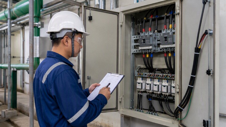
Cable schedule fields procurement should control
A clean cable schedule saves more argument than almost any meeting. It also gives the supplier enough context to challenge an unsafe or uneconomic selection before material is committed. At minimum, include these fields:
| Field | Why it matters in purchasing and production |
|---|---|
| Cable tag | Links the drum, test record, and installation location. |
| Origin and destination | Confirms route identity and prevents duplicate or missing cables. |
| Service description | Tells the supplier whether the load is motor, heater, transformer, panel feeder, UPS, crane, pump, or instrumentation power. |
| Voltage | Sets insulation level and applicable test voltage. |
| Load current | Supports ampacity checking and engineering review. |
| Route length | Affects voltage drop, drum planning, and cut length tolerance. |
| Installation method | Tray, duct, direct buried, conduit, air, or grouped installation changes derating and mechanical design. |
| Conductor size | Must match calculation after derating and voltage drop checks. |
| Number of cores | Drives cable geometry, armor choice, termination method, and minimum bending radius. |
| Conductor material | Copper and aluminum are not interchangeable at the same termination detail. |
| Insulation | XLPE, PVC, EPR, or other materials must match temperature, flexibility, and environment. |
| Sheath | The outer jacket must suit oil, sunlight, water, abrasion, flame, or chemical exposure. |
| Armor | Defines mechanical protection and sometimes grounding behavior. |
| Screen | Required for certain designs, electromagnetic control, or fault-current paths. |
| Gland type | Affects armor termination, IP rating, hazardous-area compliance, and site installation labor. |
| Termination type | Lugs, glands, kits, and panel space must suit conductor form and cable outside diameter. |
| Remarks | Use this for special marking, drum limits, inspection hold points, or end-user notes. |
The mechanism is simple: missing fields shift engineering decisions from the designer to the vendor’s quotation desk. That may reduce the first quoted price, but it increases the risk of wrong sheath material, nonconforming markings, drum lengths that cannot be pulled through site bends, or a cable that passes factory tests but fails the client’s documentation review.
Documentation for international projects
For export and project work, the paper trail is part of the product. Buyers should state which documents are required before shipment, not after the vessel is booked. Typical documentation packages include:
- Technical datasheets.
- Type test reports for the relevant cable design or standard family.
- Routine test records for the manufactured cable.
- Sample test records where the standard or inspection plan requires them.
- Factory inspection plan or inspection and test plan.
- Certificates of conformity.
- Third-party inspection certificates if contractually required.
- Packing list.
- Drum schedule, including drum number, cable tag, length, gross weight, and dimensions.
- Cable marking requirements, including language, voltage, size, standard, manufacturer, year, and meter marking where specified.
- Shipping documentation, which may include commercial invoice, bill of lading, certificate of origin, and fumigation or packaging declarations where applicable.
The trade-off is speed versus control. A stock cable with standard factory documents can often move faster, but a project-specific cable with special marking, witnessed inspection, or oil and gas documentation needs time in engineering review and production planning. The preferred choice flips when the end user’s acceptance process is strict; then saving a week at RFQ stage can cost a month at site because the documents do not match the material approval.
A certificate of conformity does not necessarily prove that every drum was individually tested for every listed property.True
Cable standards and contracts distinguish among type tests, sample tests, and routine tests. Buyers should verify which tests apply to the design, which apply to production lots, and which are performed on each manufactured length.
Quality checks that should be named, not assumed
Quality control should be written into the purchase specification in practical terms. Common checkpoints include:
- Conductor resistance.
- Insulation thickness.
- Sheath thickness.
- High-voltage withstand test.
- Spark test during extrusion where applicable.
- Dimensional inspection, including overall diameter and ovality.
- Tensile strength and elongation tests for insulation and sheath compounds.
- Flame tests where the selected standard or project specification requires them.
- Final drum inspection, including end sealing, lagging, labels, meter marking, and visible damage.
Type tests prove that a cable design can meet a standard under defined test conditions. Sample tests are taken from production according to the standard or inspection plan to verify selected properties. Routine tests are carried out on manufactured cable lengths as required by the applicable standard, often covering electrical checks such as conductor resistance and voltage withstand. Do not treat these as interchangeable; they answer different questions.
This boundary matters: the documentation approach above holds only when the project has a defined standard, stable cable design, and known installation duty. If the site has unusual heat, chemicals, cyclic movement, fire-performance rules, or hazardous-area termination requirements, the cable schedule should be reviewed by engineering before procurement freezes the RFQ.
For bulk international orders, Jinda’s integrated R&D, manufacturing, technical support, and after-sales system can help align the project specification with manufacturable cable constructions, production capability, inspection requirements, and export documentation. That support is most useful before purchase order release, when sheath material, drum schedule, cable marking, and document format can still be corrected without rework.
Common selection mistakes
Most cable selection mistakes are not exotic engineering failures; they are ordinary procurement and installation shortcuts that were never checked against the actual circuit. The expensive part is that they often pass the first visual review, then show up later as hot cable trays, nuisance trips, failed inspections, damaged drums, or joints installed where no joint was budgeted.
- Buying by amp rating only
A cable that carries the load current on paper may still be wrong if nobody checks:
- Voltage drop over the actual route length
- Motor starting or transformer inrush
- Short-circuit withstand time
- Grouping with other loaded cables
- Ambient temperature inside trays, ducts, tunnels, or roof runs
- Whether it is buried, clipped in air, pulled in conduit, or laid in tray
This is a common trap on pump skids, long warehouse feeders, and rooftop equipment. Ampacity protects the conductor from overheating under steady load; it does not guarantee acceptable voltage at the equipment terminals, nor does it prove the cable survives fault energy until the breaker or fuse clears. A cable selected only from nameplate full-load current is not a complete selection.
Treating cable size names as interchangeable
A 50 mm² conductor, a 1/0 AWG conductor, and a kcmil size are not “close enough” just because they appear near each other in a comparison chart. Different standards use different conductor definitions, insulation assumptions, installation reference methods, and ampacity tables.
The safe purchasing habit is to specify the governing standard, conductor cross-sectional area or size system, conductor material, insulation type, voltage rating, and the ampacity basis. If a project mixes IEC-style metric cable with North American equipment lugs, the terminal range and listing matter as much as the cable size. I have seen perfectly good cable delayed on site because the lug barrel, gland, or crimp die set did not match the conductor class.
Choosing the cheapest sheath for the wrong environment
Sheath material looks like an easy cost saving until the cable is dragged through oily pits, exposed to UV on a pipe rack, buried in wet soil, or installed where rodents are a known problem. The outer sheath is not just cosmetic; it is the first barrier against water ingress, abrasion, chemicals, sunlight, and flame spread.
Typical risk checks include:
- Oil and fuel exposure near compressors, presses, generators, and hydraulic units
- UV exposure on roofs, solar fields, ports, and outdoor cable trays
- Standing water, wet ducts, or direct burial
- Chemical washdown, acids, alkalis, solvents, or process residues
- Abrasion at tray edges, floor crossings, and moving equipment
- Rodent attack in tunnels, farms, warehouses, and remote substations
Flame-performance requirements in buildings, tunnels, ships, and public infrastructure
The trade-off is plain: better sheath and cable construction cost more at purchase, but the cheap option can convert a cable run into a maintenance item.
Using building wire in an industrial job it was never meant for
Building wire may be suitable inside fixed conduit or panels, but that does not make it suitable for every power circuit. Flexible equipment, cable trays, outdoor machinery, buried routes, wet wells, cranes, and emergency systems often need a different cable family.
Check whether the application actually calls for:
- Flexible cable for moving or vibrating equipment
- Armored cable for mechanical protection
- Direct-burial cable for soil contact
- Tray-rated cable for cable tray installation
- Submersible cable for pumps and wet service
- Fire-resistant cable for circuits that must operate during a fire
Shielded or screened cable where electrical noise or fault control requires it
The boundary is important: a protected, dry, indoor conduit run may be a perfectly acceptable place for standard building wire if local code allows it. The mistake is carrying that assumption into a cable tray, pump pit, or outdoor yard without review.
Installing aluminum cable as if it were copper
Aluminum conductors can be commercially sensible on large feeders, especially where material cost and weight matter. They need the right terminals, jointing methods, torque control, and inspection discipline. Where the supplier or project specification calls for antioxidant compound, use it; do not leave that decision to whoever happens to be terminating the cable on night shift.
Practical controls include:
- Terminals rated for aluminum or copper-aluminum use
- Correct crimp dies or mechanical lug ranges
- Manufacturer-specified tightening torque
- Re-torque or inspection practice where required by the equipment documentation
- Protection against moisture and galvanic corrosion at joints
- Adequate bending space, since larger aluminum conductors may need more room than the copper size they replace
Ignoring bending radius and pulling tension
Cable can be damaged before it is ever energized. Excessive pulling force can stretch conductors, deform insulation, open up shields or screens, and disturb armor. Tight bends at tray drops, manholes, cabinet entries, or drum handling points can crack sheath, flatten cable geometry, or stress insulation.
This is one of those site issues that looks harmless in photos until you peel the sheath back. Pulling tension, sidewall pressure, minimum bend radius, roller spacing, lubricant compatibility, and winch control should be checked against the cable manufacturer’s installation guidance, not guessed from crew experience.
Mixing standards without engineering review
International projects often combine equipment, cables, glands, panels, and test documents from different regions. That can work, but only when somebody reconciles the differences.
Watch for mismatches in:
- Voltage rating terminology, such as 0.6/1 kV versus other low-voltage designations
- Core identification and color codes
- Flame, smoke, and halogen classifications
- Routine and type test requirements
- Approval marks and inspection documents
- Conductor class and terminal compatibility
Armor or screen earthing practice
Procurement teams sometimes see two cables with similar descriptions and treat them as alternates. Engineering may not agree once the project specification, local authority, or insurance requirement is checked.
Forgetting coordination with protective devices
Cable and protection are one system. The breaker, fuse, relay setting, overload curve, earth-fault protection, and prospective short-circuit current all affect whether the cable is properly protected.
Poor coordination can create several different failures:
- Overload protection set too high for the installed cable ampacity after derating
- Fault current not cleared fast enough for the cable short-circuit withstand
- Protective device trips during normal motor starting
- Earth-fault protection that does not detect the expected fault path
Cable upsized for voltage drop but still not checked for terminal or protection compatibility
The mechanism is simple but often missed: fault current heats the conductor very quickly, and clearing time determines whether the insulation system sees a survivable event or a damaging one. The preferred choice can flip here; a larger cable may help voltage drop and thermal margin, but a revised protective device or relay setting may be the actual fix.
Ordering the wrong length, drum, or packaging
Cable purchasing is not finished when the electrical specification is correct. Insufficient spare length, poor drum planning, or packaging that cannot survive site handling can create avoidable joints and schedule pain.
Confirm before release:
- Measured route length, not just drawing length
- Spare length at both ends for termination, rerouting, and future maintenance
- Pulling sequence and maximum practical drum size
- Whether the site has forklifts, cranes, drum jacks, and suitable access roads
- Drum length matching cable routes to avoid unplanned joints
- End sealing for storage, shipping, rain, and humid sites
Labeling that matches circuit schedules and inspection requirements
A procurement saving on drum utilization can disappear fast if the installer has to make an extra joint in a wet trench or wait a week for a replacement drum. Cable selection is technical, but cable delivery is still a plant-floor logistics job.
Frequently asked questions
How do I know what size power cable I need?
Start with the load current, not the equipment name alone. You need the running current, duty cycle, cable route length, installation method, ambient temperature, grouping with other cables, conductor material, insulation temperature rating, and acceptable voltage drop. In practice, the selected size is the larger result from ampacity after derating and voltage-drop calculation.
Can I use a higher-rated cable than required?
Yes, if the cable still fits the terminals, glands, tray space, bending radius, protection settings, and budget. A higher voltage rating or larger conductor is usually acceptable electrically, but oversizing can create awkward terminations, heavier pulling loads, and unnecessary copper or aluminum cost. Protection devices must still match the circuit and local code.
A higher-rated cable is automatically safer in every installation.False
Higher voltage class or larger conductor size may improve electrical margin, but safety also depends on correct termination, short-circuit rating, earthing, mechanical protection, fire behavior, and protective-device coordination.
Is copper always better than aluminum for power cables?
Copper is not always the better purchase; it is the more compact conductor for the same current. Aluminum can be economical on feeders, large cross-sections, and long runs where space and termination design allow for the larger conductor size. Copper usually wins in tight panels, moving connections, smaller circuits, and locations where maintenance staff may not be disciplined about aluminum-rated lugs, oxide inhibitor, and torque checks.
What is the difference between power cable and control cable?
Power cable is built to carry load current to equipment, panels, motors, heaters, pumps, or distribution boards. Control cable carries signals, interlocks, commands, permissives, instrument contacts, or low-current control power. The construction may look similar from a distance, but the design priorities differ: current capacity and thermal rise for power cable; core identification, shielding, noise immunity, and flexible termination for control cable.
How much voltage drop is acceptable?
A practical design target is often around 3% for branch circuits and 5% total for feeder plus branch circuit, but the governing project specification or local electrical code takes priority. Motors, VFDs, long lighting runs, welders, and sensitive process equipment may need tighter limits. Long cable routes often require a larger conductor even when the ampacity table says the smaller size can carry the current.
Do I need armored cable?
Use armored cable where the cable needs mechanical protection against impact, crushing, rodents, rough handling, or exposed installation damage. It is common in industrial yards, cable trenches, direct-burial routes when specified, and plants where forklifts and maintenance work are not gentle. If the cable is fully protected in conduit, tray, or a controlled service duct, armor may add cost, diameter, and pulling stiffness without much benefit.
What cable should I use outdoors?
Outdoor cable needs a sheath suitable for sunlight, rain, temperature swing, and site chemicals. Check for UV resistance, water resistance, sheath material, flame requirements, and whether the cable will be on tray, clipped to steelwork, pulled through conduit, or exposed to abrasion. A cable that survives indoors can crack outdoors after a few summers if the sheath compound was never intended for sunlight.
What cable is suitable for underground installation?
Underground cable selection depends on whether it is direct buried, installed in duct, placed in a trench, or run through a manhole system. The cable may need water-blocking, moisture-resistant sheath, armor or metallic screen, termite or rodent resistance, and a construction rated for soil conditions. Thermal resistivity of soil matters too; dry sand, crowded ducts, and hot ground can cut ampacity noticeably compared with an open-air tray.
What does 0.6/1 kV mean on a cable?
A 0.6/1 kV rating is a common low-voltage power cable rating. The first value refers to the rated voltage between conductor and earth or metallic screen, and the second refers to rated voltage between conductors. It is not the load current rating, and it does not by itself tell you the conductor size, ampacity, insulation material, or installation suitability.
Can one cable carry both power and control cores?
Sometimes, but only when the cable is designed and specified for that duty. Mixed power and control cores can simplify installation on packaged equipment, hoists, cranes, and small machines, but separation, shielding, voltage rating, interference, safety circuits, and termination layout must be checked. I would avoid casual mixing on noisy motor feeders or VFD circuits unless the manufacturer and project engineer approve the construction.
Why does the same cable size have different amp ratings in different tables?
Ampacity changes because the table assumptions change. The same conductor size can have different ratings depending on:
- Installation in air, tray, conduit, duct, soil, or direct burial
- Ambient air or soil temperature
- Number of loaded conductors
- Cable spacing and grouping
- Insulation type, such as XLPE with typical 90 C continuous conductor rating
- Soil thermal resistivity for underground runs
- Local standard, safety factor, and installation category
Do not mix one table’s ampacity with another table’s derating factors unless the standard permits it.
What information should I send to a cable manufacturer for a quotation?
Send enough detail for the supplier to quote a cable that can actually be manufactured, inspected, packed, and installed. At minimum, include:
- Rated voltage, such as 0.6/1 kV where applicable
- AC or DC system, phase count, frequency, and earthing arrangement
- Load current, motor starting details, or equipment rating
- Route length and acceptable voltage drop
- Conductor material preference: copper or aluminum
- Required conductor size, or request sizing support with load data
- Core count, including neutral and earth requirements
- Insulation, sheath, armor, screen, and flame requirements if specified
- Installation method: tray, conduit, duct, direct burial, outdoors, indoors, submerged risk
- Ambient temperature, soil condition, grouping, and chemical or UV exposure
- Applicable standard, test requirements, packing length, drum type, and delivery destination
- Drawings, single-line diagram, cable schedule, or photos of the installation area where available
Your final specification check
The best power cable is not simply the cheapest cable that carries the calculated current. It is the cable that is electrically adequate, environmentally suitable, mechanically protected, standards-compliant, testable, and practical for the installer to pull, terminate, inspect, and maintain over its service life.
Before releasing a purchase order, freeze the requirement in a cable schedule or datasheet. At minimum, check these items one last time:
- System voltage and voltage class: operating voltage, maximum system voltage, AC or DC, earthing arrangement, and required cable rating such as 0.6/1 kV where applicable.
- Phase and circuit arrangement: single-phase, three-phase, neutral requirement, protective earth, parallel runs, and whether cores are combined in one cable or installed as singles.
- Load current and duty cycle: full-load current, continuous or intermittent operation, diversity assumptions, emergency duty, cyclic loading, and expected future spare capacity.
- Route length and voltage drop: actual installed length, not straight-line distance; include vertical rises, tray detours, gland plate routing, and termination slack.
- Installation method: buried direct, duct bank, ladder tray, perforated tray, conduit, air, tunnel, shaft, or flexible equipment connection.
- Ambient and thermal conditions: soil temperature and resistivity, grouping, sun exposure, roof runs, hot process areas, enclosed panels, and seasonal extremes.
- Conductor material and size: copper or aluminum, solid or stranded, class of conductor, allowable termination type, bending space, and lug compatibility.
- Core count and identification: number of power cores, neutral size, earth core, control cores if any, color or number marking, and phase identification practice.
- Insulation, sheath, armor, and screening: XLPE or other insulation, PVC/PE/LSZH sheath, steel wire armor, steel tape armor, non-magnetic armor for single-core AC circuits, metallic screen, or EMC screen for drive duty.
- Flame and fire performance: flame retardant, low smoke halogen-free, fire-resistant or circuit integrity requirements, as defined by the project standard or local code.
- Applicable standard and testing: IEC, BS, VDE, ASTM, GB, or project-specific standard; routine tests, type-test evidence where required, factory inspection, and requested test reports.
- Packing and logistics: drum size, cable length tolerance, export packing, lifting method, storage conditions, end sealing, and drum marking.
- Documentation: datasheet, compliance certificate, test report, packing list, drum schedule, installation notes, and traceability records requested by the project.
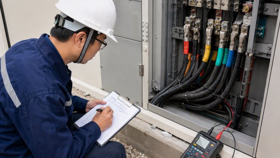
Ask for engineering review before ordering if the job has any of the usual troublemakers: long cable runs, tight voltage-drop limits, motor starting complaints, VFD-fed motors, aluminum conductors, underground installation, wet or chemically aggressive areas, high ambient temperature, fire-survival circuits, medium-voltage systems, or public projects where code compliance will be inspected hard. These are the jobs where a cable that looks acceptable on ampacity can still cause nuisance trips, failed inspections, overheating at terminations, or an expensive re-pull.
Send the supplier enough information to remove guesswork. Useful files include:
- Single-line diagram.
- Cable schedule or load list.
- Route drawings, tray layouts, or trench sections.
- Project specification and referenced standards.
- Site photos showing trays, ducts, panels, glands, soil conditions, or exposed outdoor routes.
- Existing cable markings if this is a replacement.
- Required delivery lengths, drum limits, and destination packing requirements.
Jinda can review your cable schedule, single-line diagram, or project requirements for technical support, manufacturing feasibility, and bulk quotation. For a workable inquiry, include voltage, current, route length, installation method, conductor preference, insulation and sheath requirements, armor or screening needs, applicable standard, test documentation, packing requirements, and estimated order quantity.