Choose the wrong power cable and the problem rarely appears on day one. It shows up later as warm trays, nuisance trips, cracked insulation, water ingress, failed terminations, or a purchasing batch that cannot pass site inspection. That becomes downtime, rework, expedited freight, and warranty arguments, so the practical starting point is to classify cables by voltage, conductor, insulation, construction, and service environment before comparing prices.
Power cables are commonly grouped by voltage class, conductor material, insulation system, construction, installation environment, and application. The main types include low-voltage, medium-voltage, high-voltage, copper, aluminum, PVC-insulated, XLPE-insulated, armored, unarmored, flexible, fire-resistant, submarine, mining, solar, and other special-purpose power cables.
The tricky part is that these labels overlap. A 0.6/1 kV cable can be copper or aluminum, PVC or XLPE, armored or unarmored, tray-laid or buried, and each choice changes ampacity, bending behavior, termination method, delivery cost, and inspection risk. That is where cable selection stops being a catalog exercise and becomes an engineering and procurement decision.
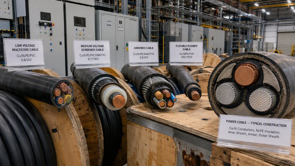
Voltage classes and insulation systems
Voltage class and insulation system are the backbone of power cable classification because they set the electrical stress the cable can withstand, the way it must be screened and terminated, and the tests it must pass before shipment or energization. A cable that looks mechanically suitable can still be electrically wrong if its rated voltage, insulation material, or accessory system does not match the network.
Exact voltage boundaries vary by IEC, national standards, utility practice, and market terminology, but the engineering split is usually practical enough:
| Cable class | Common voltage designation examples | Typical function | Insulation and construction emphasis |
|---|---|---|---|
| Low-voltage power cable | 0.6/1 kV is common under IEC practice | Building feeders, plant distribution, panels, motors, pumps, lighting power | Current capacity, fire behavior, installation toughness, cost |
| Medium-voltage power cable | Often from 3.6/6 kV up to 18/30 kV for many distribution systems | Utility distribution, substations, large motors, renewable collection, mining feeders | Electrical stress control, screens, partial discharge performance, jointing quality |
| High-voltage power cable | 64/110 kV and similar transmission classes | Urban transmission, power plants, grid reinforcement, tunnel circuits | Insulation cleanliness, eccentricity control, metallic sheath or screen design, factory testing |
| Extra-high-voltage power cable | Above high-voltage transmission classes, depending on the market | Bulk transmission, grid interconnection, long links, submarine and tunnel systems | System engineering, thermal design, accessories, sheath bonding, installation risk control |
Low-voltage power cables
Low-voltage cables are usually selected around load current, installation condition, fire performance, mechanical protection, and procurement availability rather than complex electrical stress control. In many IEC-based specifications, 0.6/1 kV covers a large share of fixed low-voltage power distribution, although local codes and product standards must still be checked before purchase.
Typical LV duties include:
- Main and sub-main building feeders
- Industrial distribution panel outgoing circuits
- Motor and pump supplies
- Lighting and small power distribution
- HVAC and utility plant feeders
- Control-associated power supply where the cable is carrying actual power, not just signals
- Tray, conduit, duct, buried, and armoured installations, depending on site risk
PVC, XLPE, and rubber-based insulation are common here. PVC is economical and easy to process, which is why it appears so often in building and general industrial cables. Many PVC-insulated power cables are rated around 70°C continuous conductor temperature, subject to the governing standard, installation method, and manufacturer data. XLPE and many EPR-insulated power cables are commonly rated around 90°C, again subject to the actual standard and datasheet.
The mechanism is simple but often underestimated: conductor temperature drives insulation aging, voltage withstand margin, and ampacity. If a cable is bunched on a tray above a boiler room, buried in warm soil, or pulled through an already crowded duct bank, the current rating printed in a catalog table may no longer apply without derating. A buyer comparing only conductor size and price can easily buy a cable that is nominally correct but thermally overloaded in service.
Medium-voltage power cables
Medium-voltage cables are no longer just “bigger low-voltage cables”; they are controlled electrical components. Once the system voltage rises into distribution classes such as 3.6/6 kV, 6/10 kV, 8.7/15 kV, 12/20 kV, or 18/30 kV, the cable normally requires conductor screens, insulation screens, metallic screens or sheaths, and terminations designed to manage the electric field.
These cables are used in:
- Utility primary distribution networks
- Substation incomers and feeders
- Large industrial plants with internal MV distribution
- Mining and tunneling feeders
- Wind farm collection networks
- Solar collector systems and inverter station feeders
- Large motor supply circuits for compressors, mills, crushers, fans, and pumps
- Shore power, port, and heavy infrastructure distribution
The conductor screen smooths the electric field around the conductor strands. The insulation screen creates a controlled outer boundary for the insulation. The metallic screen or sheath carries capacitive charging current and earth-fault current, depending on design and bonding. If those layers are damaged, stripped incorrectly, or paired with the wrong termination kit, the cable may pass a basic continuity check but fail later through tracking, partial discharge, or insulation breakdown.
For medium-voltage and higher systems, the accessory is part of the insulation system, not a separate hardware afterthought. This is where plant-floor discipline matters: clean stripping, correct screen cutback, stress-control components, torque on lugs, and moisture control during jointing can matter as much as the cable itself. I have seen otherwise decent MV cable installations compromised by dust, rainwater in joint pits, and crews using a knife like they were preparing a low-voltage gland.
The trade-off is cost and skill versus reliability. MV cable costs more because the construction is more controlled and testing is stricter; the installation also needs trained jointers and compatible kits. But trying to save money by using a lower voltage class, an unapproved termination, or a cable without the required screen design shifts the cost into outage risk, fault damage, and difficult fault location later.
High-voltage and extra-high-voltage power cables
High-voltage and extra-high-voltage cables are engineered transmission assets, not commodity feeders. They serve urban grid reinforcement, power plant export circuits, submarine links, tunnels, transmission corridors, and grid interconnections where failure access is difficult and outage cost can be severe.
At these voltage levels, insulation purity, void control, eccentricity, metallic sheath design, water blocking, impulse withstand, partial discharge behavior, and factory process control become central. XLPE is widely used in modern HV and EHV cable systems, but the cable design is only one part of the circuit. Outdoor terminations, GIS terminations, joints, link boxes, sheath bonding, earthing, surge protection, route thermal resistivity, pulling tension, bending radius, and commissioning tests all sit in the same engineering package.
A small manufacturing or installation imperfection has a larger consequence because electrical stress is concentrated. If the insulation is eccentric, one side sees higher stress. If contamination or a microvoid is present, partial discharge can start under operating or overvoltage conditions. If sheath bonding is wrong, circulating currents can heat the cable and reduce ampacity. These are not catalog-line problems; they need project-specific design review and qualified installation practice.
The main conclusion has a boundary: high-voltage practices should not be blindly imposed on every low-voltage purchase, because that would add cost without useful benefit. But once the cable enters MV and above, treating voltage class as a nameplate detail rather than a system design requirement becomes a bad bet.
Major insulation systems and where they fit
Insulation choice is a thermal, electrical, mechanical, environmental, and commercial decision. The best material is the one that fits the voltage class, operating temperature, installation abuse, fire requirement, moisture exposure, flexibility need, and accessory ecosystem.
- PVC: Common for economical low-voltage service. It is easy to manufacture, widely available, and suitable for many building and general industrial feeders. Its limitation is usually thermal performance and behavior under severe fire or high-temperature duty compared with higher-grade systems.
- XLPE: A cross-linked thermoset insulation widely used in modern low-voltage, medium-voltage, and high-voltage power distribution. It offers good dielectric strength and a common 90°C continuous conductor rating in many designs, subject to standard and manufacturer confirmation. It is less forgiving of poor MV jointing practice than a buyer might expect because electrical stress control still dominates.
- EPR: A thermoset rubber insulation valued for flexibility, moisture tolerance, and demanding industrial service. It is often considered where handling, vibration, trailing duty, or wet environments are part of the job, although exact suitability depends heavily on the full cable design.
- Mineral insulation: Used where fire survival and heat resistance are the primary requirements. These cables are specialized, less convenient to terminate, and not chosen simply for ordinary feeder work.
- Paper-insulated lead-covered cable: A legacy or specialized system found in older networks and some utility contexts. It may remain in service for decades, but replacement, jointing, and interface work require people who understand that system; it should not be mixed casually with modern polymeric cable designs.
Thermoplastic insulation, such as many PVC compounds, softens when heated and hardens again when cooled. Thermoset insulation, such as XLPE and EPR, is cross-linked so it resists deformation better at elevated operating temperature. That difference affects ampacity, overload tolerance, short-circuit behavior, and how the cable survives hot trays, tight cleats, or a motor room that runs warmer every summer.
A cable with the same conductor size can be unsafe if it has a lower voltage rating or incompatible insulation and accessories.True
Conductor size mainly addresses current-carrying capacity and voltage drop. Voltage rating, insulation system, screens, terminations, and tests determine whether the cable can withstand the electrical stress of the system.
What Uo/U and Um mean
Rated voltage expressions are easy to skim past on a datasheet, but they are not decoration. In IEC-style notation:
- Uo is the rated power-frequency voltage between conductor and earth or metallic screen.
- U is the rated power-frequency voltage between phase conductors.
- Um is the maximum system voltage for which the equipment may be used, under the relevant standard.
For example, a cable designation such as 0.6/1 kV refers to phase-to-earth and phase-to-phase voltage ratings. Medium-voltage designations follow the same logic, but the insulation thickness, screening system, impulse withstand, and test requirements increase with the voltage class.
Voltage class is not only about normal operating voltage. It affects insulation wall thickness, stress grading, lightning or switching impulse withstand, screen design, test voltage, jointing method, termination clearance, creepage distance, and safe working practice. A cable can operate at normal voltage for a while and still have inadequate margin for transients, earth faults, contaminated terminations, or aging.
Testing and procurement checks tied to insulation class
The higher the voltage class, the more the buyer should care about test regime and documentation. Routine factory voltage testing is common across power cable categories, while partial discharge testing becomes especially important for medium-voltage and higher cables. Insulation resistance checks, conductor resistance testing, dimensional checks, and type tests according to the applicable IEC, national, or project standard all need to align with the specified cable type.
For procurement, do not approve substitutions by conductor size alone. Check at least:
- Rated voltage designation, including Uo/U and Um where applicable.
- Insulation material and continuous conductor temperature rating.
- Applicable product standard and required test reports.
- Screen, sheath, armour, water-blocking, and fire-performance requirements.
- Compatibility with joints, terminations, glands, lugs, and earthing method.
- Installation condition: buried, duct, tray, tunnel, wet area, direct sunlight, chemical exposure, or moving duty.
- Short-circuit rating and earth-fault duty for metallic screens or sheaths.
- Minimum bending radius and pulling tension limits from the manufacturer.
The risky substitution is the one that “fits” during installation: same conductor area, similar outside diameter, acceptable price, and available stock. If the voltage grade is lower, the insulation system is different, or the accessory family does not match, the defect is hidden until commissioning, a wet season, a switching surge, or a fault event exposes it.
Conductor materials and constructions
Conductor choice creates a distinct cable type before anyone specifies XLPE, PVC, armor, or outer sheath. The metal determines resistance, weight, termination behavior, theft risk, and price exposure; the construction determines bendability, diameter, jointing method, and how easily the cable can be pulled through a tray, duct, trench, or panel gland.
Copper or aluminum conductors
Copper is the compact, mechanically forgiving choice; aluminum is the weight- and cost-driven choice. Electrical-grade aluminum is commonly around 61% IACS conductivity by volume, compared with copper commonly referenced at 100% IACS, so an aluminum conductor normally needs a larger cross-section to carry similar current at similar loss.
An aluminum power cable usually needs a larger conductor cross-section than a copper cable for the same electrical duty.True
Electrical-grade aluminum has lower volumetric conductivity than copper, so equivalent resistance normally requires more conductor area. Final sizing still depends on installation method, thermal conditions, and allowable voltage drop.
In practice, the comparison is not just conductivity:
| Factor | Copper conductor | Aluminum conductor |
|---|---|---|
| Conductivity | Higher conductivity, smaller conductor for same resistance | Lower conductivity, larger cross-section usually required |
| Weight | Heavier, harder on long vertical drops and tray loading | Much lighter, useful for long feeders and overhead or underground distribution |
| Mechanical strength | Better tolerance of handling, bending, and repeated termination work | Softer; needs correct lugs, jointing practice, and torque control |
| Termination | Familiar to most electricians; compact lugs fit crowded panels | Requires aluminum-rated or bimetallic connectors, oxide control, and proper compound where specified |
| Corrosion behavior | Good general performance; bare copper can still suffer in aggressive atmospheres | More sensitive to galvanic issues, especially where connected to copper or exposed to moisture |
| Commercial exposure | Higher material cost; price swings affect large projects sharply | Often attractive for bulk projects, long runs, and utility-style distribution |
Aluminum wins many long feeder jobs because conductor weight affects installation labor, pulling tension, tray loading, and drum handling. On a 400 m underground feeder, saving mass can matter as much as saving metal cost; fewer strained winch pulls and less wrestling at the trench edge are not spreadsheet fantasies. The trade-off is physical size: larger aluminum cores can increase cable outside diameter, bending radius, gland size, and termination enclosure space.
Copper tends to stay favored in compact switchrooms, machine feeds, ships, data center power distribution, and plants with many termination points. It tolerates awkward routing and repeated maintenance better. If a maintenance crew is opening a molded-case breaker panel twice a year because production keeps modifying the line, copper is usually less troublesome than oversized aluminum with special lugs jammed against a door clearance.
The boundary is simple: neither metal is “better” without the installation. A well-terminated aluminum feeder in a stable duct bank can be the correct engineering choice; a poorly terminated one in a damp panel with mixed metals can become a heat source.
Solid, stranded, compacted, flexible, and sector-shaped conductors
Conductor construction controls how the cable bends, packs, and terminates. Standards in many markets describe conductor classes broadly as rigid solid, rigid stranded, flexible, and extra-flexible, but the exact class numbers and test requirements must be checked against the applicable IEC, national, or project specification.
Common constructions include:
- Solid conductors
Usually used at smaller sizes where stiffness is still manageable. They are simple, dimensionally stable, and easy to terminate, but become difficult to bend as size increases. In plant work, solid conductors are fine for fixed lighting or small power circuits, not for a large motor feeder that must snake through a crowded gland plate. - Stranded conductors
Built from multiple wires to improve flexibility and handling. Standard stranded copper or aluminum is the everyday construction for many low-voltage and medium-voltage power cables. It gives a practical balance between manufacturing cost, pulling behavior, and termination reliability. Compacted stranded conductors
Strands are compressed to reduce voids and outside diameter. This can lower insulation and sheath material use and help fit a rating into a smaller cable envelope. The price paid is slightly stiffer handling compared with a non-compacted stranded conductor of similar size, and termination tools must match the actual conductor form.Flexible stranded conductors
Made with many finer wires. These are used where movement, tight bending, or frequent connection is expected, such as welding leads, temporary power, mobile equipment, or certain control-power tails. They should not be substituted into fixed power circuits without checking lug compatibility, short-circuit rating, and the governing installation code.Sector-shaped conductors
Common in multi-core power cables, especially larger low-voltage cables. Instead of round conductors, each phase is shaped like a sector of a circle so the cores pack more efficiently. This reduces overall cable diameter and can save insulation, bedding, armor, and sheath material. The downside is bending behavior: sectoral cores have preferred bending directions, and careless pulling can distort the cable or make joint preparation unpleasant.
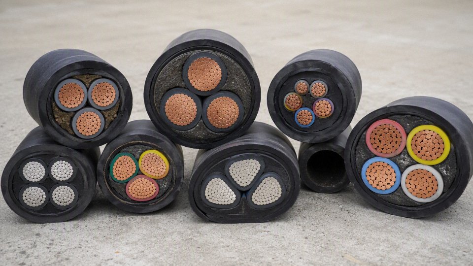
Circular compacted conductors are common where manufacturers want a round, efficient core with good dimensional control. Sectoral and shaped conductors make most sense where the finished cable diameter drives cost or installability, such as large four-core low-voltage feeders. In medium-voltage cables, conductor shape also interacts with insulation screen geometry, so the cable design and accessories must be treated as a tested system, not mixed casually from catalog pages.
Single-core, multi-core, neutral, and protective arrangements
Core arrangement is another way power cables are classified. It affects installation method, electromagnetic behavior, fault return paths, gland selection, and accessory count.
Typical arrangements include:
- Single-core cables for each phase or pole, common in larger feeders and many medium-voltage circuits. They are easier to handle per drum than one huge multi-core cable, but three single cores must be installed with correct spacing and bonding practice to control induced currents and heating in metallic armor, screens, or nearby steelwork.
- Two-core cables for single-phase AC, DC pairs, or phase-neutral circuits.
- Three-core cables for three-phase systems without a separate neutral, common for motors and balanced loads.
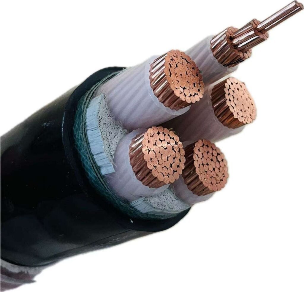
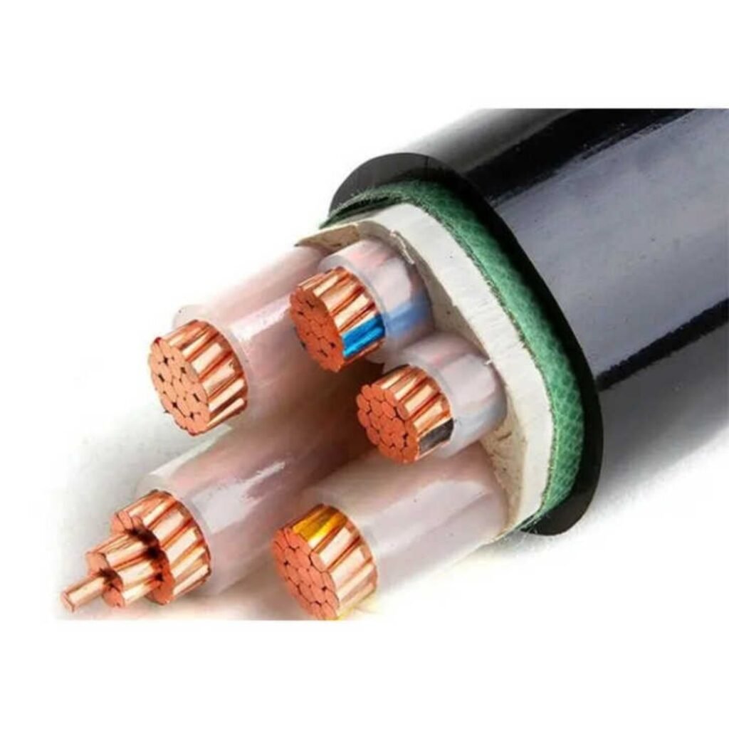
- Four-core cables for three-phase plus neutral, often seen in low-voltage distribution.
- Five-core cables for three-phase, neutral, and protective earth where the design calls for all conductors in one cable.
- Multi-core configurations where power conductors are combined with auxiliary cores for heaters, brakes, monitoring, or small control supplies, provided the voltage separation, EMC, and standard requirements allow it.
A common procurement mistake is buying by cross-section alone: “300 mm² aluminum” or “185 mm² copper” is not a complete cable definition. Ampacity must be verified from conductor material, insulation temperature rating, installation method, grouping, ambient temperature, soil thermal resistivity, duct fill, burial depth, and permissible voltage drop. A 90°C XLPE-insulated cable in free air and the same cross-section cable buried in hot, dry soil inside a congested duct bank are not the same electrical asset.
Corrosive and humid environments add another layer. Bare copper is normal for many power cables. Tinned copper is often selected for marine, offshore, humid, chemical, and high-sulfur atmospheres because the tin layer improves resistance to surface corrosion and can help maintain solderability or termination condition. Aluminum conductor systems in these environments need particular attention to water blocking, compatible lugs, joint sealing, and galvanic separation from copper or steel hardware.
Direct current applications also deserve a separate check. DC feeders may need different polarity identification, insulation aging review, voltage stress assessment, and fault-clearing assumptions than an AC feeder of similar voltage. The catalog cross-section is only the starting point; the final selection belongs to the load profile, route, thermal environment, protection design, and the way the cable will actually be terminated in the field.
Low-voltage cable families
Low-voltage power cables usually sit closest to the load: final distribution, building feeders, MCC outgoing circuits, small and medium motor supplies, lighting, emergency systems, low-voltage utility connections, and equipment power inside plants. In IEC-style purchasing, many of these are specified around 0.6/1 kV, but the actual cable family still depends heavily on movement, fire behavior, installation protection, and the consequence of a failure.
| Cable family | Typical construction | Common use | Major selection risk | Procurement note |
|---|---|---|---|---|
| PVC-insulated / PVC-sheathed power cable | Copper or aluminum conductors, PVC insulation, PVC outer sheath; armored or unarmored | Building feeders, light industrial distribution, fixed equipment circuits | Heat, smoke, acid gas, and oil exposure can exceed the cable’s practical limits | Economical and widely available; verify temperature rating, flame grade, and installation method |
| XLPE-insulated LV power cable | XLPE insulation with PVC, PE, or LSZH sheath; often multi-core or single-core | Industrial feeders, infrastructure, pumps, fans, distribution boards | Higher operating temperature does not mean unlimited overload allowance | Good general-purpose industrial choice where thermal margin matters |
| Rubber flexible cable | Fine-stranded conductor, rubber or elastomer insulation/sheath | Portable tools, construction power, mobile equipment, welding supply, temporary installations | Buying a “flexible” cable that is not rated for duty cycle, oil, abrasion, or outdoor use | Specify flex class, sheath compound, voltage rating, and service environment |
| Trailing and reeling cable | Highly flexible conductors, reinforced elastomer sheath, sometimes central support or control cores | Cranes, reels, mining support equipment, mobile machinery | Torsion, crush, drum diameter, and travel speed are often underestimated | Ask for minimum bending radius, tensile load, torsion rating, and reel duty data |
| Building wire / single-core insulated conductor | Single insulated conductor, commonly used inside containment | Conduits, panels, distribution boards, internal wiring | Treating it like a feeder cable exposed to impact, water, or sunlight | Match to local wiring rules, conduit fill, color coding, and terminal temperature |
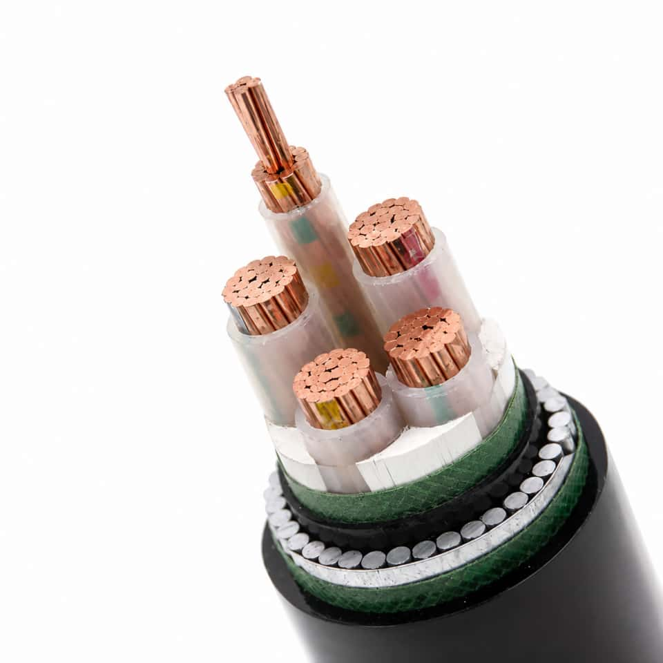
| Armored LV cable | Multi-core or single-core cable with steel wire armor, steel tape armor, or non-magnetic armor | Direct burial, yards, tunnels, outdoor plant distribution | Wrong armor type on single-core AC circuits can create heating problems | For single-core AC, verify magnetic effects and specify suitable non-magnetic armor if required |
| Unarmored LV cable | Insulated cores with bedding and sheath, no metallic armor | Trays, risers, ducts, protected indoor routes | Mechanical protection is assumed but not actually present on site | Use where routing is controlled and impact risk is low |
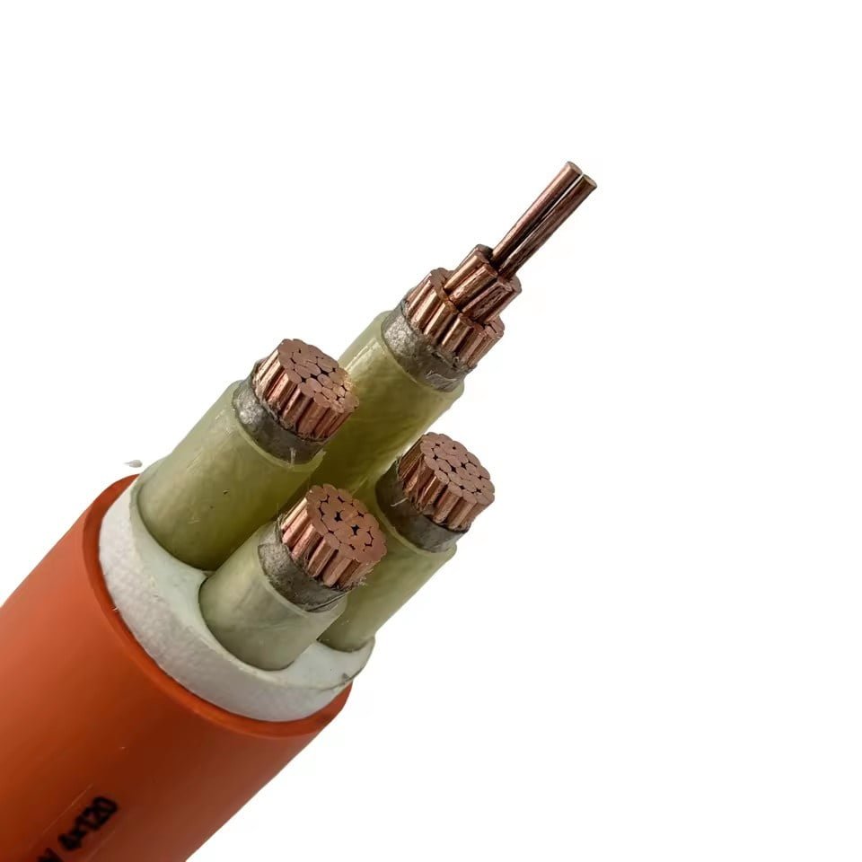
| Fire-resistant cable | Mica tape or other circuit-integrity system plus insulation and sheath | Emergency lighting, fire pumps, smoke extraction, alarms, evacuation systems | Confusing flame retardancy with circuit survival | Specify the required circuit integrity test and compatible glands/supports |
| Flame-retardant / LSZH / low-smoke low-halogen cable | Various insulation and sheath compounds designed for fire behavior control | Buildings, tunnels, public infrastructure, indoor industrial routes | Using one fire term to cover all fire hazards | Separate flame spread, smoke density, halogen acid gas, and circuit integrity requirements |
| Solar PV DC cable | Flexible tinned copper commonly used, UV/ozone/weather-resistant insulation and sheath | PV string wiring and DC collection | Ordinary AC cable may age poorly under sunlight, heat cycling, and DC polarity exposure | Specify DC voltage rating, UV resistance, temperature range, and polarity identification |
| BESS and DC feeder cable | Flexible or semi-flexible insulated cable, often heat- and flame-performance focused | Battery racks, PCS connections, DC bus feeders | Short-circuit energy and enclosure heat are underestimated | Coordinate cable size with protective devices, terminals, routing, and battery enclosure design |
| Marine / shipboard LV cable | Compact multi-core cable, flame-performance sheath, oil-resistant options | Ship power, auxiliaries, lighting, marine control power | Land cable substituted without class or marine fire/oil requirements | Check classification society and project specification before purchase |
| Hybrid auxiliary power cable | Power cores plus control or instrumentation cores in one assembly | Compact equipment wiring, packaged systems, some auxiliaries | Electromagnetic interference and unsafe mixing of circuit classes | Keep power and signal separate unless the design, shielding, and standard allow combined routing |
PVC-insulated and PVC-sheathed low-voltage cables are still the workhorse in many commercial buildings and light industrial jobs because they are cost-effective, easy to terminate, and familiar to installers. A typical PVC-insulated cable may be rated for 70°C continuous conductor operation, subject to the applicable standard and manufacturer data. That is enough for many fixed feeders, lighting circuits, and distribution boards where ambient temperature is controlled and the cable is not sitting above a hot process line.
The trade-off is not hidden: PVC is economical, but it is not the best answer where smoke, corrosive acid gas, oil contamination, low-temperature flexibility, or higher thermal loading is critical. I have seen PVC feeder routes perform perfectly for years in dry indoor tray, then give trouble in the same plant when maintenance rerouted a section near steam piping and solvent washdown. The cable type did not change; the environment did.
XLPE-insulated low-voltage power cables give more thermal and dielectric margin than many PVC-insulated designs. Many XLPE or EPR-insulated power cables are commonly associated with 90°C continuous conductor ratings, again subject to the governing standard, installation method, and cable maker’s published limits. That extra thermal headroom helps in industrial feeders, infrastructure ducts, pump stations, and motor circuits where load variation is not tidy.
The mechanism is straightforward: conductor current creates heat, insulation slows heat transfer, and the surrounding installation either removes or traps that heat. XLPE tolerates higher conductor temperature than PVC in many designs, so the same circuit may carry more current or survive short overloads better, provided the termination, grouping factor, ambient temperature, and protective device settings also agree. A higher insulation temperature rating does not rescue a cable that has been undersized, overgrouped, or terminated into equipment rated for a lower temperature.
Flexible rubber-insulated cables are a different family, not just “soft fixed cables.” They are used where movement is part of normal operation: portable equipment, construction sites, temporary power boards, welding-related supply, mobile machinery, mining support equipment, and maintenance hookups. The conductor stranding, insulation compound, sheath toughness, and sometimes textile or rubber reinforcement all matter because failure usually starts from flex fatigue, jacket cuts, oil swelling, or crushed cores rather than pure electrical stress.
Trailing and reeling cables push that problem further. A cable on a crane reel, mobile stacker, mining machine, or moving gantry sees repeated bending, tension, torsion, abrasion, and occasional abuse from wheels, pallets, rocks, or careless forklift traffic. The buyer should not stop at voltage and cross-section; the useful questions are:
- What is the minimum bending radius during operation and storage?
- Is the cable reeled under tension or only laid out by hand?
- Does the drum create torsion, reverse bending, or multi-layer winding pressure?
- Will the sheath see oil, hydraulic fluid, slurry, sunlight, or sharp aggregate?
- Are control cores, fiber elements, or earth monitoring conductors included?
Building wire and single-core insulated conductors belong mainly inside conduits, panels, switchboards, distribution boards, and internal wiring systems. They are often bought by color, size, insulation type, and local wiring rule rather than as heavy multi-core feeder cables. The mistake is using single-core building wire as if it has the same mechanical and environmental protection as a sheathed, armored power cable. It usually does not.
Armored low-voltage cables are selected where the route can be hit, buried, pulled through rough ducts, or exposed to rodent and mechanical damage. Steel wire armor is common on multi-core cables where tensile strength and impact resistance are needed; steel tape armor is often used where radial protection is valued and flexibility is less important. For single-core AC cables, magnetic armor can cause circulating losses and heating, so non-magnetic armor, such as aluminum wire armor, may be required depending on the design. Verify this against the cable standard, installation arrangement, and supplier data rather than treating armor as a generic add-on.
Unarmored low-voltage cables are right for trays, conduits, risers, plant rooms, and protected indoor routes where mechanical damage is controlled by installation. They are easier to handle, cheaper to gland, and lighter on cable tray loading. The choice flips toward armor when the route moves outdoors, underground, across a yard, through a tunnel, or into an area where maintenance crews routinely drag hoses, scaffold poles, or metal parts near the cable run.
Fire-performance terminology causes expensive misunderstandings. Flame-retardant cable is intended to limit flame spread. Low-smoke zero-halogen cable reduces smoke and halogen acid gas during fire, which matters in tunnels, public buildings, control rooms, and enclosed escape routes. Low-smoke low-halogen designs reduce those hazards to a lesser degree depending on the formulation and test requirement. Fire-resistant power cable is different: it is designed to maintain circuit integrity for a specified fire exposure, typically for emergency lighting, fire pumps, smoke control, alarms, evacuation systems, and critical control power.
Solar photovoltaic DC cables, battery energy storage system cables, and DC feeder cables sit at the edge of the traditional low-voltage conversation because DC behavior and exposure conditions change the risk profile. PV cables need sunlight, ozone, weathering, thermal cycling, and polarity identification performance; a common indoor AC cable is usually the wrong substitute on a roof. BESS and DC feeder cables must be coordinated with enclosure heat, short-circuit protection, terminal design, bending space, and service access. DC arcs do not self-extinguish the same way AC arcs do, so protection and routing deserve more attention than the cable schedule sometimes gives them.
Marine and shipboard low-voltage cables add another layer: compact construction, oil resistance, flame behavior, weight control, and classification society requirements where the vessel or offshore project demands them. A land-based plant cable may look electrically adequate on paper but still fail the procurement requirement for a shipyard package.
Instrumentation-power hybrid and auxiliary power cables should be specified cautiously. Combining power and signal cores can save installation space in packaged equipment, but it can also introduce electromagnetic interference, fault segregation problems, and maintenance confusion. Keep power and instrumentation separate unless the equipment design, shielding, voltage separation, termination layout, and applicable standard clearly support a hybrid construction.
Medium-voltage cable families
Medium-voltage power cables are the feeders that sit between plant transformers, switchgear lineups, substations, renewable collection circuits, utility distribution rings, and large motors. In many IEC-based projects this means cable ratings such as 3.6/6 kV through 18/30 kV, with the exact selection driven by system voltage, earthing method, fault level, installation environment, and accessory design.
At this voltage class, the cable is no longer just “insulated copper or aluminum with a jacket.” The insulation screen, metallic screen, water barrier, armor, termination workmanship, and sheath bonding arrangement all start to affect service life. A medium-voltage cable system is only as strong as its cable, accessories, installation practice, and grounding design working together.
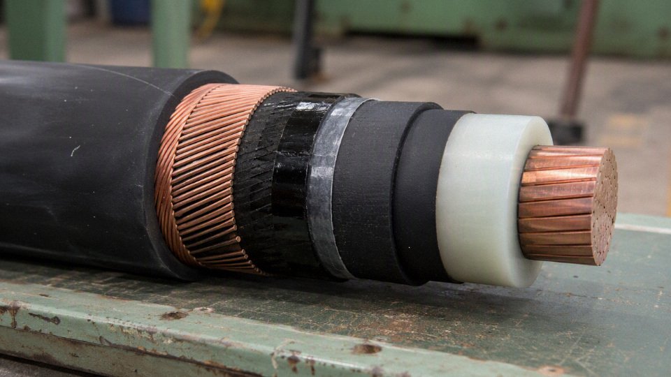
Single-core medium-voltage cables
Single-core MV cables are widely used in ducts, trenches, direct burial routes, substations, long distribution feeders, and renewable-energy collection systems. They are easier to pull in long lengths than a heavy three-core cable, and they let designers manage phase spacing, bending radius, and routing one phase at a time. On big industrial sites, I have seen single-core cables become the practical choice simply because the pulling crew, winch, rollers, and duct bends could not sensibly handle a three-core drum of the same circuit rating.
The trade-off is that single-core cables need more engineering around electromagnetic effects. Each phase produces a magnetic field, so armor selection, metallic screen bonding, sheath circulating current, and installation formation matter. Trefoil formation usually reduces external magnetic fields and inductive reactance; flat formation may suit tray or trench geometry but can increase magnetic imbalance if spacing is not controlled. For single-core AC cables, magnetic steel armor is normally avoided because it can heat from induced losses; non-magnetic armor such as aluminum wire armor is commonly used where armor is required.
Sheath bonding is not a clerical detail. Solid bonding, single-point bonding, and cross-bonding change sheath voltage, circulating current, losses, and touch-voltage risk. The right method depends on route length, fault current, grounding grid design, joint bay locations, and local safety rules, so it should be verified against the project standard and accessory supplier guidance rather than decided at the purchasing desk.
Three-core medium-voltage cables
Three-core MV cables put all three phase conductors under one shared outer sheath, often with common bedding, armor, and serving. They are attractive where compact routing matters: industrial plants, wind farms, utility distribution feeders, port installations, and sites where one drum, one pull, and one cable identification tag simplify site handling.
They are not automatically “better” or “worse” than single-core cables. A three-core cable can reduce installation clutter and simplify three-phase circuit management, but it is heavier, stiffer, and harder to pull through difficult duct routes. Heat dissipation may also be less favorable than separated single-core cables in some buried or duct-bank arrangements. The preferred choice flips when the route geometry, pulling tension, drum access, or thermal design becomes the limiting factor rather than the purchase price per meter.
What layers make up a modern MV XLPE cable?
A typical medium-voltage XLPE cable is built as a controlled electrical-stress system, not as a stack of protective plastics. The screens create a smooth electric field around the insulation; without them, small voids, protrusions, contamination, or eccentricity would concentrate stress and shorten life.
A common layer sequence is:
- Conductor — copper or aluminum, round compacted or shaped depending on design and core arrangement.
- Conductor screen — a semi-conductive layer that smooths the electrical interface between conductor and insulation.
- XLPE insulation — the primary dielectric, commonly rated for higher continuous conductor temperatures than PVC designs, subject to the cable standard and manufacturer data.
- Insulation screen — another semi-conductive layer that maintains a controlled outer insulation surface.
- Metallic screen, tape, sheath, or concentric neutral — provides electrostatic shielding, grounding path, and sometimes earth-fault current capacity.
- Bedding, separator, or water barrier — cushions metallic layers and may include swelling tapes, powders, or yarns.
- Armor where required — steel wire, steel tape, or non-magnetic armor depending on mechanical risk and single-core versus three-core construction.
- Outer sheath — typically selected for moisture, abrasion, sunlight, oil exposure, flame performance, termite risk, or local installation conditions.
The mechanism is simple but unforgiving: a damaged screen edge, poor semi-con stripping, or contaminated termination surface can create partial discharge at operating voltage. The cable core may have passed factory tests, yet the installed circuit can still fail early because the field control at the termination or joint was compromised.
Metallic screens, tapes, sheaths, and concentric neutrals
The metallic layer is often misunderstood because it performs several jobs at once. It is not just “some copper for grounding.” It can shield the electric field, carry capacitive charging current, provide an earth-fault return path, limit touch voltage, and interface with surge arresters, terminations, and link boxes.
| Metallic construction | Where it is commonly used | Strengths | Watch points |
|---|---|---|---|
| Copper wire screen | Industrial MV feeders, utility distribution, wind and solar collection circuits | Flexible, can be sized for earth-fault duty, generally easier to terminate than full metallic sheaths | Fault rating depends on wire area, fault duration, and bonding; wires can be damaged during stripping |
| Copper tape screen | Distribution cables and compact MV designs | Good electrostatic shielding, tidy construction, common in many specifications | Lower fault-current capacity unless designed with enough tape area; tape overlap and corrosion protection matter |
| Metallic sheath, such as lead or aluminum-based barrier designs | Wet routes, tunnels, utility networks, long-service infrastructure | Strong radial moisture barrier; can also contribute to fault return and mechanical robustness depending on design | Heavier, less flexible, more expensive; lead handling and environmental requirements must be checked |
| Concentric neutral | Common in some utility distribution systems, especially grounded systems | Combines neutral and screen functions; suits certain utility protection philosophies | Must match system grounding and protection design; not interchangeable with a simple screen in every network |
Screen short-circuit rating should be specified, not assumed. The required value depends on earth-fault current magnitude and clearing time. A buyer who only states conductor size and voltage grade leaves a dangerous gap; the screen may be electrically adequate for shielding but undersized for fault duty.
Water-blocked and moisture-resistant MV cables
Water damage in MV cable systems usually enters through sheath cuts, poor joint sealing, damaged ducts, flooded manholes, or long-term soil exposure. Water-blocked cables use water-swellable tapes, powders, or yarns to reduce longitudinal water migration after sheath damage. The purpose is containment: if the outer sheath is nicked by a rock, a cable roller, or an over-enthusiastic knife during termination, the swelling materials help stop water from travelling freely along the cable.
Radial water barriers address a different path. Aluminum-plastic laminated sheaths, lead sheaths, and other metallic barrier systems are used where water pressure, wet soil, tunnels, ducts, river crossings, or long design life justify the added cost and stiffness. A laminated sheath may be a good compromise for many buried distribution circuits; lead sheaths are heavier and less pleasant to handle, but still specified in some demanding wet-service or utility applications because they form a very robust moisture barrier.
Tree-retardant XLPE and enhanced insulation systems are also used in moisture-prone networks. Water treeing is a material-and-system issue: moisture, electrical stress, contaminants, insulation morphology, screen quality, and operating history all interact. A tougher outer jacket helps keep water out, but it does not by itself turn an ordinary cable into a water-tree-resistant system. This conclusion stops holding where the environment is dry, well-drained, mechanically protected, and maintenance access is good; in those cases, the extra moisture package may not pay back compared with better route protection and installation control.
Armored, mining, trailing, submarine, and renewable collector MV cables
Armored MV cables are selected where mechanical damage is credible: mining sites, refineries, steel plants, direct burial runs, congested utility corridors, and industrial facilities with forklifts, excavators, vibration, or rough backfill. Steel wire armor gives tensile and impact protection, steel tape armor can suit certain buried three-core designs, and non-magnetic armor is normally required for single-core AC cables to avoid heating losses. Armor adds protection, but it also increases weight, bending radius, pulling tension, and termination time.
Mining and trailing MV cables are a separate family in practice. They must tolerate frequent relocation, flexing, dragging, impact, abrasion, flame exposure, and sometimes oil, water, and crushed rock. Flexibility, flame resistance, toughness, impact resistance, and repairability matter more than elegant tray routing. These cables should be bought against the applicable mining or mobile-equipment standard and the machine duty cycle, not treated as ordinary fixed MV feeders with a thicker sheath.
Submarine and underwater MV cables serve island supplies, offshore renewable projects, river crossings, port infrastructure, dredging areas, and intake structures. They need water barriers, armoring, route-specific tensile strength, seabed or riverbed protection, and carefully planned pulling tension. A short river crossing can be a tougher procurement package than a long land feeder because bend control, winch load, current, burial depth, vessel access, and repair strategy all come into play.
Renewable-energy collector cables for wind and solar plants bring their own mix of problems:
- Long radial routes with many joints and terminations.
- Cyclic loading from changing generation output.
- Direct burial exposure, soil thermal variation, and seasonal moisture.
- Ultraviolet exposure where cables rise above grade or run on structures.
- Grounding and screen bonding coordination across many collection feeders.
- Plant layouts that change late, after civil work has already started.
The counter-intuitive part is that the most expensive MV failures often start outside the factory-made cable core. A knife score in the sheath, an unsealed gland, incorrect heat-shrink work, poor screen cutback, wrong lug tooling, dirt inside a joint, or a bonding link left in the wrong position can take down a feeder that was perfectly manufactured.
For medium-voltage procurement, the purchase file should normally define:
- Voltage grade and system earthing method.
- Conductor material, size, and construction.
- Insulation type, such as XLPE, tree-retardant XLPE, or EPR where specified.
- Metallic screen type and short-circuit rating.
- Outer sheath material and required environmental resistance.
- Water-blocking and radial water-barrier requirements.
- Armor type, including non-magnetic requirements for single-core AC circuits.
- Fire performance, flame retardance, smoke, and halogen requirements where applicable.
- Drum length, maximum drum size, and pulling constraints.
- Installation method: duct, tray, trench, direct burial, tunnel, underwater, mobile service, or mixed route.
- Required standard compliance, test reports, accessory compatibility, and marking language.
That document set saves money because it prevents the common “same voltage, same size” substitution error. At MV level, two cables with the same conductor cross-section can behave very differently once fault current, water exposure, armor losses, pulling route, and termination practice are included.
High-voltage and specialty cables
High-voltage and specialty cables are not ordinary distribution cables scaled up in diameter. They are selected for transmission duty, system stability, environmental survival, or a dominant hazard that would make a standard power cable unsafe or short-lived. Once a project reaches high-voltage class, long water crossings, tunnels, rail traction, offshore service, or fire-survival duty, the cable becomes part of an engineered system rather than a commodity line item.
A high-voltage cable is not just a thicker medium-voltage cable.True
Higher voltage raises electrical stress, accessory complexity, sheath voltage behavior, testing requirements, and route engineering demands. Conductor size matters, but insulation cleanliness, extrusion control, metallic sheath design, bonding arrangement, and installation quality often decide service reliability.
High-voltage and extra-high-voltage transmission cables
High-voltage cables are used where power transfer is large enough, critical enough, or spatially constrained enough that overhead lines or ordinary distribution feeders are not suitable. In IEC-style terminology, ratings such as 64/110 kV and above are commonly treated as high-voltage transmission territory, with extra-high-voltage projects extending beyond that depending on the grid standard and national practice.
Typical applications include:
- Grid interconnections between major substations
- Urban underground transmission where overhead corridors are unavailable
- Power export from large thermal, hydro, solar, wind, or offshore generation sites
- Industrial megaprojects such as refineries, smelters, LNG plants, steel works, and data center campuses
- Long-distance energy transfer across land or water
- Cross-border interconnectors and island supply links
The operating issue is not simply ampacity. At high voltage, the insulation system must manage electric field stress continuously for decades. A small void, contamination particle, eccentric insulation layer, poor screen interface, or badly installed joint can become a partial-discharge site. That defect may not trip the circuit on day one, but it can grow through electrical treeing until the failure appears years later, usually at the worst possible time.
High-voltage XLPE underground cables
Modern underground high-voltage cables are commonly based on XLPE insulation, subject to the applicable standard, voltage class, and project specification. These cables often use large copper or aluminum conductors, conductor screens, ultra-clean XLPE insulation, insulation screens, metallic sheaths or screens, water-blocking layers, outer sheaths, and sometimes laminated metallic moisture barriers.
The manufacturing controls are much tighter than for normal low-voltage or medium-voltage cables. Precision triple extrusion is used to keep the conductor screen, insulation, and insulation screen bonded and concentric. Clean-room material handling is not a marketing detail here; contamination in the insulation can become an electrical stress concentration. For a procurement manager, this is why high-voltage cable purchasing usually involves factory qualification records, type test evidence, routine test plans, drum handling rules, and accessory compatibility checks before release.
Metallic sheath design deserves careful attention. Lead sheaths, corrugated aluminum sheaths, copper wire screens, aluminum laminates, and composite barriers each solve different problems:
- Radial moisture blocking
- Earth fault current carrying capacity
- Mechanical protection during pulling or burial
- Induced sheath voltage management
- Corrosion resistance in soil or tunnel environments
Sheath bonding is one of the areas where I see expensive mistakes. Single-point bonding reduces circulating sheath currents but can create higher standing sheath voltages. Solid bonding is simpler but can add losses through circulating currents. Cross-bonding reduces sheath losses on long routes, but it needs correct section lengths, link boxes, surge voltage limiters, earthing design, and disciplined installation. Get the phasing or link-box wiring wrong, and the thermal model that justified the cable size may no longer be true.
Factory routine testing for high-voltage cables is not paperwork decoration. High-voltage withstand tests, partial discharge checks, conductor resistance measurement, sheath integrity tests, and dimensional inspections are used to catch defects before shipping. The exact test regime must come from the governing standard and project specification; no responsible supplier should replace that with a generic brochure promise.
Legacy and specialized high-voltage cable systems
Oil-filled and fluid-filled high-voltage cables are established technologies, especially in older transmission networks and some specialized applications. They can perform well when properly maintained, but they bring a different operating burden from dry extruded cables. Fluid pressure, reservoirs, leak detection, route containment, joint condition, and environmental response plans become part of the asset management program.
That trade-off is straightforward: fluid-filled systems can be robust in certain legacy grids and historically proven voltage classes, but they demand monitoring and environmental control. In a dense urban route, a small leak is not just a maintenance event; it can become a regulatory and public-relations problem. For replacement projects, the decision often turns on compatibility with existing joints, available outage windows, civil constraints, and whether a full circuit conversion is practical.
Gas-insulated and compressed gas cable systems occupy an even more specialized corner. They may be considered where transmission capacity is required through highly constrained corridors, such as tunnels, substation approaches, or short high-power links where conventional cable heat dissipation or installation geometry is difficult. These systems are engineered packages, not reel-and-pull products, and require specialist design, gas monitoring, enclosure integrity control, and maintenance planning.
Submarine, offshore, and HVDC cables
Submarine high-voltage cables are used for offshore wind export, island interconnectors, cross-border links, platform power supply, and long water crossings. They may be HVAC or HVDC depending on distance, power level, grid interface, charging current limits, and converter economics. For longer routes, HVDC often becomes attractive because it avoids the reactive charging current that limits long AC submarine cables, but the converter stations add cost, footprint, losses, controls, and protection complexity.
Submarine cable design has to survive more than electrical stress. The cable may need:
- Longitudinal and radial water blocking
- Steel wire armoring for tensile strength and seabed protection
- Fiber optic elements for communication or monitoring
- Bedding layers that tolerate compression and handling
- Protection against abrasion, fishing gear, anchors, rocks, and installation tension
HVDC cable technology has its own design issues. Mass-impregnated paper-insulated cables remain relevant in some high-power and long-distance projects, while extruded polymer HVDC cables are widely used in newer systems where their voltage rating, temperature capability, and qualification record fit the project. Polarity reversal behavior matters for line-commutated converter systems, while voltage-source converter systems have different operating profiles. In extruded insulation, space charge accumulation and decay must be understood because trapped charge can distort the electric field after load changes or polarity events. This is not an area for “equivalent” substitutions without system studies and manufacturer confirmation.
Aerial distribution solutions near the cable boundary
Overhead covered conductors and aerial bundled cables sit between bare overhead lines and fully insulated underground cables. They are often used in distribution networks to reduce faults from tree contact, improve public safety margins, simplify service drops, or clean up congested pole routes.
They should not be confused with underground power cables. Covered conductors may reduce incidental contact faults, but many are not designed to be touch-safe under all energized conditions. Aerial bundled cable systems rely on mechanical suspension design, UV-resistant insulation, messenger arrangements, clamps, piercing connectors, and correct sag-tension practice. They solve a different problem than buried cable: lower civil cost and easier access, at the price of continued exposure to wind, ice, sunlight, and pole hardware condition.
Specialty power cables selected by hazard
Specialty cables are often selected by the dominant hazard first, then by conductor size and voltage rating. That is backwards from a simple switchboard feeder schedule, but it is how the plant actually fails: fire, oil, chemicals, vibration, mud, saltwater, torsion, or smoke toxicity usually kills the cable before copper area does.
| Specialty cable category | Main selection driver | Practical engineering concern |
|---|---|---|
| Fire-survival mineral-insulated cables | Circuit operation during fire | Bending radius, termination skill, moisture sealing, verified fire rating |
| Heat-resistant silicone rubber cables | High ambient or radiant heat | Mechanical softness, tear resistance, suitable glands and supports |
| Oil-resistant industrial cables | Lubricants, cutting fluids, hydrocarbons | Sheath swelling, cracking, cable tray contamination |
| Chemical-resistant cables | Acids, alkalis, solvents, process vapors | Exact chemical concentration, temperature, exposure time |
| Nuclear-grade cables | Radiation, safety classification, aging | Qualification records, traceability, plant-specific approval |
| Airport lighting power cables | Airfield circuits and wet duct banks | Insulation integrity, series circuit compatibility, water resistance |
| Railway and metro power cables | Traction, tunnels, vibration, smoke limits | Fire performance, low smoke, halogen limits where specified, continuity of service |
| Offshore, marine, and port crane cables | Saltwater, mud, torsion, movement | Classification rules, low-temperature flexibility, armor, drum duty |
Railway and metro cables are a good example of system-driven selection. A traction feeder may carry heavy cyclic load, sit near signaling circuits, pass through tunnels, and be exposed to vibration from rolling stock. Fire behavior is often just as important as ampacity because smoke density, corrosive gases, and circuit survival affect evacuation and emergency operation.
Offshore, marine, and port crane cables bring a different set of headaches. Saltwater finds weak jacket compounds, mud attacks sheaths, low temperatures stiffen flexible cables, and crane reels punish poor torsion design. Classification society requirements may apply, and the acceptable cable is usually the one that matches the vessel, platform, crane, or port authority specification rather than the cheapest item with the same voltage printed on the sheath.
For high-voltage and specialty cable projects, the cable manufacturer, accessory supplier, route designer, installer, and testing contractor should be aligned before production starts. That alignment is where sheath bonding, joint bays, pulling tensions, fire ratings, chemical exposure, drum lengths, test methods, and commissioning responsibilities get fixed while there is still time to change the design. Once the cable is manufactured and shipped, many of those choices are no longer cheap engineering decisions; they are outage risks, claims, or scrap.
Sheath, armor, and fire ratings
A large share of “different power cable types” are really differences in the protective outer system: sheath compound, armor, bedding, tapes, fillers, and fire-performance rating. These layers may not carry current, but they often decide whether a cable survives sunlight, wet soil, tray abrasion, oil mist, rodents, pulling tension, tunnel fire rules, or ten years of maintenance abuse.
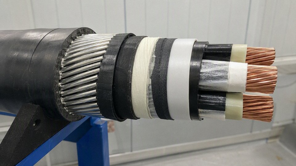
What the outer sheath actually does
The outer sheath is the cable’s working jacket. On a clean indoor cable tray it may only need modest abrasion resistance and clear marking; in a refinery trench, mine, port crane, or direct-buried feeder, it becomes the first defense against water, oil, chemicals, UV, impact, soil movement, and installation damage.
In practice, sheath selection usually balances these functions:
- Moisture protection: limits water ingress into insulation screens, bedding, fillers, and metallic components. This matters heavily for buried and outdoor medium-voltage cables.
- Ultraviolet resistance: prevents cracking and embrittlement on rooftop, solar, outdoor tray, and exposed plant runs.
- Abrasion resistance: protects the cable during pulling over rollers, ladder tray edges, ducts, and backfilled trenches.
- Chemical and oil resistance: prevents swelling, softening, cracking, or loss of mechanical strength in plants with hydraulic oil, cutting fluid, fuel, solvents, or process chemicals.
- Flame behavior: controls flame spread, smoke density, and acid gas emission, depending on the compound and tested construction.
- Mechanical containment: helps hold the cable geometry together under bending, pulling, thermal cycling, and armor pressure.
- Identification: provides color, printed markings, meter marks, voltage class, standard reference, manufacturer name, batch codes, and sometimes project-specific traceability.
The mechanism is simple but often underestimated: a sheath compound that absorbs oil or cracks under UV stops being a barrier, then moisture and dirt reach the bedding or metallic layers, then corrosion, tracking, screen damage, or insulation contamination starts. The electrical failure may appear years later, but the first mistake was usually mechanical or environmental.
Common sheath materials and where they fit
No sheath material is best everywhere. The usual procurement mistake is copying a familiar specification into a different environment, such as using a general indoor PVC cable for an exposed coastal tray or demanding low-smoke zero-halogen for a wet industrial yard without checking abrasion and water performance.
| Sheath material | Typical strengths | Common limits and cautions |
|---|---|---|
| PVC | Economical, easy to process, decent general-purpose performance, common in building and industrial LV cables | Can generate dense smoke and acid gases in fire unless specially formulated; check oil, UV, and low-temperature requirements |
| Polyethylene, including MDPE and HDPE | Strong moisture resistance, good abrasion resistance, good outdoor and buried service when properly specified | Generally poorer flame behavior than fire-rated building compounds; not usually the first choice for populated escape routes |
| Low-smoke zero-halogen compounds | Lower smoke and halogen acid gas emission during fire; favored in tunnels, metros, airports, hospitals, data centers, high-rises, ships, and evacuation areas | Usually costs more; mechanical toughness, water resistance, and installation temperature must be checked by compound grade |
| Chlorinated polyethylene, or CPE | Good resistance to weathering, oils, chemicals, and flame in suitable formulations | More specialized; verify exact compound performance rather than assuming all CPE jackets behave alike |
| Chlorosulfonated polyethylene, or CSP | Strong weather, ozone, chemical, and heat-aging resistance in demanding flexible or industrial service | Higher-cost specialty choice; availability and processing can affect lead time |
| Polyurethane, or PUR | Excellent abrasion and tear resistance; useful for moving equipment, reels, robotics, and rough handling | Fire and halogen performance varies by formulation; may not suit every fixed building installation |
| Rubber compounds, including PCP, EPR-based, and other elastomers | Flexibility, impact tolerance, trailing cable suitability, temporary power, mining, and mobile plant use | Needs correct grade for oil, flame, temperature, and mechanical duty |
| Application-specific jackets | Termite-resistant, rodent-resistant, mud-resistant, hydrocarbon-resistant, cold-resistant, or solar-rated designs | The description must tie back to a tested compound, construction, or project standard, not just a catalog adjective |
Polyethylene sheaths are often favored for direct burial, wet ducts, outdoor distribution, and cable routes where abrasion during pulling is a known risk. PVC or low-smoke zero-halogen materials are more often selected for buildings, tunnels, metro systems, airports, hospitals, high-rise towers, ships, and data centers because fire and evacuation consequences dominate the decision. The preferred sheath changes as soon as the main risk changes: wet soil pushes the buyer toward moisture toughness, while occupied enclosed infrastructure pushes the buyer toward smoke, halogen, and flame performance.
Armor types and the single-core AC trap
Armor gives mechanical protection; it does not automatically make a cable suitable for every installation. The armor material, lay, coverage, bonding, corrosion protection, and compatibility with single-core or multi-core construction all matter.
Common armor constructions include:
- Steel wire armor: widely used on multi-core power cables where pulling strength and impact protection are needed.
- Steel tape armor: useful for crush and mechanical protection, often less flexible than wire armor and not ideal where high pulling tension is expected.
- Galvanized steel armor: steel armor with zinc coating to improve corrosion resistance, still dependent on sheath integrity and soil chemistry.
- Aluminum wire armor: non-magnetic and lighter than steel; often considered for single-core AC applications.
- Aluminum tape armor: non-magnetic tape protection where the design and bending requirements allow it.
- Braided armor: used on some flexible, instrumentation, marine, or special-duty cables where flexibility and coverage are both needed.
- Double armor: applied in demanding pulling, heavy mechanical, submarine, mining, or special installation cases, subject to project design rather than catalog substitution.
The easily missed issue is single-core alternating-current cable. Magnetic steel armor around a single AC conductor can experience induced currents and heating because the armor links the conductor’s alternating magnetic field. For single-core AC circuits, engineers normally need non-magnetic armor, special bonding arrangements, trefoil installation, or a manufacturer-approved design verified against the applicable standard and load condition.
Armor is not automatically a protective earth conductor.True
Armor may be used as a protective conductor only when the cable design, armor cross-section, electrical continuity, gland termination, bonding method, fault-current capacity, and governing standard all allow it. Many projects still require a separate protective earth conductor.
Hidden construction details buyers should not ignore
Bedding, inner sheath, fillers, separators, binders, and wrapping tapes look like minor factory details until a cable is bent around a tight corner or pulled through a bad duct. They influence roundness, core position, armor support, flame propagation path, water migration, and how cleanly the cable strips during termination.
A few shop-floor checks are worth asking for on serious orders:
- Bedding thickness and material: protects insulated cores from armor pressure and sharp metallic edges.
- Fillers and lay-up quality: keep the cable round; poor roundness makes glands, cleats, and terminations harder.
- Separator and binder tapes: control friction between layers and support clean manufacturing, especially in armored and screened cables.
- Flame or water-blocking tapes: may be needed for vertical shafts, tunnels, MV routes, or wet ducts, but they must match the required test regime.
- Inner sheath under armor: improves mechanical protection and can help maintain cable geometry during pulling and bending.
This is one place where factory discipline shows. A cable can meet conductor size and voltage rating on paper but still be miserable to install if the lay-up is loose, the bedding is uneven, or the sheath tears when pulled over a tray rung with a burr left by last night’s maintenance crew.
Fire descriptions that are often confused
Fire wording in cable purchasing needs careful reading. Similar-sounding terms describe different behaviors, and they are not interchangeable.
- Flame-retardant: designed and tested to limit flame spread under specified test conditions. It may stop propagating flame after ignition is removed.
- Fire-resistant: designed to maintain circuit integrity for a defined time under fire test conditions, often with mica tape or other fire-survival layers.
- Fireproof: a loose marketing word and usually a bad specification term unless tied to an exact standard and performance requirement.
- Low-smoke: limits smoke generation under a specified test; it does not automatically mean zero halogen.
- Zero-halogen: formulated without halogenated materials, reducing acid gas risk during combustion, subject to test confirmation.
- Low-halogen: reduced halogen content, not the same as zero-halogen.
- Sunlight-resistant: suitable for UV exposure when tested or rated accordingly.
- Termite-resistant and rodent-resistant: may use physical barriers, additives, harder sheaths, or armor; local pest conditions matter.
- Oil-resistant: resists specified oil exposure; engine oil, hydraulic oil, and transformer oil are not always equivalent test exposures.
- Chemical-resistant: must name the chemical family, concentration, temperature, and exposure duration.
A flame spread test and a circuit integrity fire test answer different questions. A flame-retardant cable may limit propagation along a tray, yet fail electrically early in a fire because insulation, conductor support, or accessories cannot survive the heat. A fire-resistant cable for a fire pump, smoke extraction fan, emergency lighting circuit, or alarm supply must be selected with the whole system in mind: cable, cleats, glands, trays, joints, terminations, and installation route.
Smoke and acid gas are not academic concerns in enclosed infrastructure. In tunnels, metros, airports, hospitals, data centers, high-rise buildings, ships, and evacuation corridors, dense smoke can block escape and acid gases can damage switchgear, electronics, and structural assets long before flames reach them. The boundary is that LSZH is not automatically the toughest outdoor or buried sheath; where water, abrasion, and chemicals dominate, the compound has to be selected against those exposures as well.
Marking, color, and traceability
Outer marking saves labor later. A good sheath print gives maintenance crews and inspectors enough information to identify the cable without opening a gland or hunting through old drawings.
Specify what must appear on the sheath:
- Manufacturer identification
- Cable type or construction code
- Voltage rating
- Conductor material and size
- Number of cores
- Applicable standard or project specification
- Fire performance description where relevant
- Meter marking or sequential length marking
- Batch, reel, or traceability code
- Year of manufacture, if required by the project
- Sheath color or stripe coding for system identification
Color coding varies by country, utility, site standard, and voltage class, so it should be stated in the purchase document rather than assumed. Traceability sounds like paperwork until a shutdown crew finds three similar black armored cables in the same trench; then a clear meter mark and batch code are worth more than a cheaper jacket.
Standards and procurement checks
A usable cable enquiry should read like an engineering data sheet, not a product nickname. At minimum, send suppliers the following fields before asking for a commercial offer:
- Project country and installation authority
- Country of installation
- Utility, consultant, EPC, or end-user specification
- Local approval requirements, if any
- Applicable standard family
- IEC, BS, EN, VDE, ICEA, UL, CSA, AS/NZS, or a project-specific utility standard
- Edition or document number where known
- Any deviation sheet issued by the project owner
- Electrical rating and system data
- Voltage rating, such as 0.6/1 kV, 6/10 kV, 8.7/15 kV, 12/20 kV, 18/30 kV, or another project rating
- Alternating current or direct current
- System frequency for AC systems
- Grounding method: solidly grounded, resistance grounded, isolated, impedance grounded, or another defined arrangement
- Load current and load profile
- Permissible voltage drop
- Short-circuit current and duration
- Earth fault current and clearing time
- Harmonic content, if feeding drives, rectifiers, UPS systems, arc furnaces, or similar loads
- Motor starting current and starting frequency where relevant
- Protective device coordination requirements
- Emergency or overload duty requirements
- Cable construction
- Conductor material: copper or aluminum
- Conductor size and class of stranding
- Number of cores
- Insulation type
- Metallic screen or shield design, including required fault-current capacity
- Inner covering, bedding, sheath, and oversheath material
- Armor type, if required
- Fire performance requirement: flame retardant, low-smoke halogen-free, fire-resistant, circuit integrity, or project-specific fire classification
- Installation and service environment
- Direct burial, duct bank, tray, ladder, conduit, tunnel, riser, underwater route, overhead aerial support, flexible service, or mobile equipment
- Ambient air temperature
- Soil temperature
- Soil thermal resistivity
- Burial depth
- Cable grouping and spacing
- Sunlight exposure
- Wet location, water immersion, or water migration risk
- Oil, fuel, solvents, acids, alkalis, or process chemicals
- Rodents, termites, or other biological attack
- Salt spray or coastal atmosphere
- Altitude, where air cooling or voltage stress assumptions may be affected
- Mechanical impact, pulling tension, sidewall pressure, vibration, and bending constraints
- Supply, inspection, and documentation
- Drum length and tolerance
- Cable cutting plan
- Drum diameter, width, and gross weight limits
- Container loading limits
- Site lifting conditions: forklift, crane, spreader beam, or restricted access
- Route access to site storage
- Storage duration before installation
- End caps, moisture sealing, and export packaging
- Delivery schedule and phased shipment requirements
- Minimum order quantity constraints
- Inspection and test plan
- Required certificates, test reports, packing lists, drum schedules, and as-built documentation
Standards need careful handling because the same phrase can mean different things in different markets. IEC-based specifications are common in many international power projects, while BS, EN, and VDE requirements often appear in European, Middle Eastern, and infrastructure tenders. ICEA is widely seen in North American-style utility and industrial specifications, while UL and CSA approval may be mandatory for listed products used in regulated building or equipment applications. AS/NZS requirements appear frequently in Australia, New Zealand, and related export projects.
No single standard family is automatically “better.” The problem is mixing them casually. A cable quoted to an IEC construction standard may not satisfy a UL listing requirement; a utility MV cable specification may demand screen ratings, water blocking, or jacket tests beyond the base standard; and a building fire code may care less about conductor economics than smoke, acidity, and circuit integrity under fire. Before comparing price, confirm that every supplier is quoting to the same governing standard, the same edition, and the same project deviations.
Certification and test evidence are not paperwork decoration. They are how a buyer proves that the delivered cable matches the technical and contractual requirement after the drum has crossed a border and arrived on a congested site. For international projects, ask clearly for:
- Certificate of conformity
- Type test evidence, where the standard or project requires it
- Routine test records for the supplied batch
- Factory inspection reports, if witnessed or third-party inspection is specified
- Batch traceability from conductor, insulation, sheath compound, and finished cable drum
- Drum-by-drum packing lists and serial identification
The mechanism is simple: once cable is installed in ducts, trays, trenches, or risers, replacement cost is no longer the cable price. It becomes labor, outage time, civil access, retesting, termination rework, and schedule damage. A missing routine test record may look like an administrative issue in procurement, but it becomes a serious problem when a commissioning engineer has to explain a failed insulation resistance test two days before energization.
Installation method changes the cable type more than many buyers expect. A cable in free air on ladder tray may run cooler than the same cable buried in warm, dry soil. Ducts reduce heat dissipation; tight grouping increases mutual heating; vertical risers may need different flame spread or support considerations; underwater routes bring water pressure, abrasion, and sealing questions; mobile equipment needs flexibility and mechanical fatigue resistance rather than just ampacity on paper. The same nominal size can be acceptable in one route and undersized in another.
Environmental data is where many weak enquiries fail. Soil thermal resistivity, for example, directly affects heat removal from buried cables. If the assumed value is too optimistic, the conductor operates hotter, insulation ages faster, and the apparent saving on conductor size turns into reduced service life. Sunlight can drive sheath temperature up on outdoor tray runs. Oil exposure can soften unsuitable jacket compounds. Rodents and termites are not academic risks in some regions; they are maintenance realities, especially around substations, rail corridors, mines, plantations, and older industrial sites.
Electrical data also has commercial consequences. Higher short-circuit current may require a larger metallic screen or armor design. Long feeders may be governed by voltage drop rather than thermal ampacity. Drives and harmonic-rich loads may push neutral sizing, shielding, or heating checks. Motor feeders need starting voltage drop reviewed, not just full-load current. Emergency circuits may require different fire performance and documentation than ordinary distribution feeders.
The lowest quotation is often not lower because the factory is magically more efficient. It may be based on:
- A different standard
- A lower metallic screen short-circuit rating
- Reduced conductor cross-section tolerance assumptions
- Thinner sheath or different sheath compound
- PVC instead of low-smoke halogen-free material
- Non-armored construction where armor was expected
- No water-blocking where the route is wet
- Limited test scope
- Unacceptable drum lengths that create extra joints
- Packaging unsuitable for export handling or long storage
Quality checks should be agreed before production, not argued after shipment. Typical manufacturing and pre-shipment checks include conductor resistance, dimensional measurements, insulation thickness, sheath thickness, spark testing where applicable, voltage withstand testing, partial discharge testing for applicable medium- and high-voltage cables, hot set testing for cross-linked insulation, specified flame tests, drum marking checks, end sealing, and visual inspection. The exact test list must follow the governing standard and purchase specification.
For bulk procurement, the best results usually come from locking the technical schedule first and the unit price second. Shandong Jinda Special Cable Group’s integrated R&D, production, sales, technical support, and after-sales system is useful here because specification clarification, manufacturing feasibility, packing planning, inspection coordination, and long-term supply support can be handled as connected work rather than isolated transactions. That matters when the order is not one cable reel, but a project package crossing several voltage classes, installation environments, and delivery phases.
Frequently asked questions
What is the most common type of power cable?
It depends on the voltage class and local market practice. For fixed installation, low-voltage PVC- or XLPE-insulated power cables are among the most widely bought cable types, while medium-voltage XLPE-insulated cables are very common in utility, industrial, and infrastructure distribution. In many factories, the “common cable” on the purchasing desk is still a 0.6/1 kV multicore power cable feeding panels, motors, pumps, HVAC equipment, and lighting distribution.
What is the difference between power cable and control cable?
Power cables carry operating energy to loads: motors, transformers, switchboards, drives, heaters, and distribution panels. Control cables carry commands, interlocks, permissive signals, auxiliary power, and sometimes instrumentation-related control circuits at lower power levels.
The confusion starts because both may have copper conductors, PVC or XLPE insulation, armor, and similar-looking sheaths. The real difference is the circuit duty: current level, voltage drop sensitivity, electromagnetic interference requirements, core identification, and how the cable is terminated in the panel.
Is XLPE better than PVC?
XLPE is often the better insulation where higher conductor temperature, stronger dielectric performance, and improved thermal aging are needed. Many XLPE and EPR power cables are rated around 90°C continuous conductor temperature, while many PVC-insulated cables are rated around 70°C, subject to the standard, cable design, and installation conditions.
PVC still makes commercial sense in many low-voltage indoor and general building applications. It is economical, familiar to installers, and widely available. The better choice flips when heat, load cycling, fault withstand, or medium-voltage stress control becomes more important than initial cable price.
When should armored cable be used?
Use armored cable where the route exposes the cable to credible mechanical damage, not just because “armored sounds safer.” Typical cases include:
- Direct burial without continuous duct protection
- Industrial yards with vehicle movement or excavation risk
- Mining, quarrying, and heavy process areas
- Tunnels, trays, and exposed routes where impact is possible
- Sites with rodents, rough backfill, or poor route control
For single-core alternating current cables, armor selection needs care. Magnetic steel armor around a single AC conductor can create heating losses, so non-magnetic armor or another approved construction may be required. Verify this against the project standard and manufacturer data.
What cable is used for underground power distribution?
Underground distribution commonly uses low-voltage or medium-voltage XLPE-insulated cables, often with armor, water-blocking layers, or moisture-resistant sheaths depending on the route. The final design depends on voltage level, soil thermal resistivity, burial depth, groundwater exposure, mechanical risk, jointing practice, and local utility requirements.
A dry industrial trench is not the same duty as a flooded roadside duct bank. Water treeing risk, sheath damage during pulling, and joint quality can matter more than the cable catalog name.
What cable is used for solar power systems?
Solar systems usually use photovoltaic direct current cable between modules and string combiner equipment, selected for outdoor exposure, UV resistance, temperature range, and DC voltage rating. Larger DC feeder cables may be used between combiner boxes and inverters where the system design requires them.
After the inverter, the installation uses conventional AC power cables sized for the output current, voltage drop, installation method, and protective device coordination. Do not treat PV string cable and AC distribution cable as interchangeable just because the conductor size looks similar.
Can the same cable be used indoors and outdoors?
Yes, but only if the cable construction is approved for both environments. Check the sheath material, UV resistance, moisture protection, minimum and maximum service temperature, flame requirements, and installation standard.
In practice, failures often come from using an indoor-rated sheath outdoors on trays or rooftops. Sunlight, standing water, and seasonal temperature cycling will expose weak sheath selection faster than the electrical load does.
How do I choose cable size?
Cable size should be calculated, not guessed from a past project. The main checks are:
- Load current and duty cycle
- Permissible voltage drop
- Short-circuit thermal withstand
- Installation method and heat dissipation
- Ambient temperature and soil conditions
- Cable grouping and tray fill
- Harmonics, if relevant
- Protective device coordination
- Termination temperature limits
A conductor that is adequate in open air may be undersized in a crowded tray or buried in hot, dry soil. Copper and aluminum sizing also differs because electrical-grade aluminum has lower conductivity by volume, so equivalent aluminum cables usually need a larger cross-section.
What documents should a manufacturer provide?
For procurement, ask for documents that let engineering, quality, logistics, and site installation check the same product. A practical package normally includes:
- Technical datasheet with voltage rating, construction, conductor size, insulation, sheath, armor, and dimensions
- Applicable standard compliance statement
- Routine test report for the supplied cable
- Type test evidence where the project or standard requires it
- Quality certificate or certificate of conformity
- Packing list
- Drum schedule with lengths, drum numbers, and weights
- Installation guidance when pulling tension, bending radius, storage, or termination limits are critical
For medium-voltage and project-critical cables, do not rely on a quotation description alone. The datasheet, test documentation, and drum schedule are what prevent the wrong cable from reaching site and becoming an expensive argument at installation.
Verify your cable specification
The right power cable type is not defined by conductor size and voltage alone. A usable purchasing specification combines voltage class, conductor design, insulation system, screen or armor construction, sheath performance, installation environment, and the applicable standard, because each one changes the cable that will actually arrive on the drum.
Do not ask suppliers only for “4-core copper 0.6/1 kV” or “240 mm² medium-voltage cable” and expect equivalent quotations. Those short descriptions can hide major differences in conductor class, insulation material, metallic screen area, armor type, flame performance, water blocking, sheath compound, test requirements, and packing length. On paper the cheaper offer may look close; in the trench, tray, duct bank, or switchgear room it may become a pulling problem, a termination mismatch, or a certification delay.
Use this verification sequence before releasing an inquiry or purchase order:
- Confirm system voltage and grounding
- Rated voltage, highest system voltage, neutral grounding method, and whether the cable operates in a utility, industrial, mining, renewable, or building distribution system.
- Calculate load and fault requirements
- Continuous current, voltage drop limit, short-circuit current and duration, ambient temperature, grouping, burial depth, duct fill, and expected future load growth.
- Define the installation environment
- Indoor tray, outdoor exposed run, direct burial, duct, tunnel, wet area, corrosive soil, oil exposure, rodent risk, UV exposure, or repeated mechanical handling.
- Choose insulation and sheath performance
- PVC, XLPE, EPR, LSZH, PE, or special sheath compounds should be selected against temperature rating, fire behavior, moisture exposure, chemical contact, and regulatory requirements.
- Decide armor and screening
- Medium-voltage cables need the correct metallic screen design and screen cross-section. Armored cables need the right armor material and construction for mechanical protection, magnetic effects, installation method, and earthing practice.
- Specify fire behavior
- Flame retardant, fire-resistant, low-smoke zero-halogen, or ordinary sheath performance should match the installation area and governing code, not just a buyer preference.
- Identify standards, tests, and documents
- State IEC, national, project, or utility specifications, plus required routine tests, type-test evidence where applicable, inspection requirements, certificates, and language of documents.
- Confirm logistics
- Required drum lengths, maximum drum size or weight, delivery sequence, labeling, destination country, port or site access limits, and storage conditions.
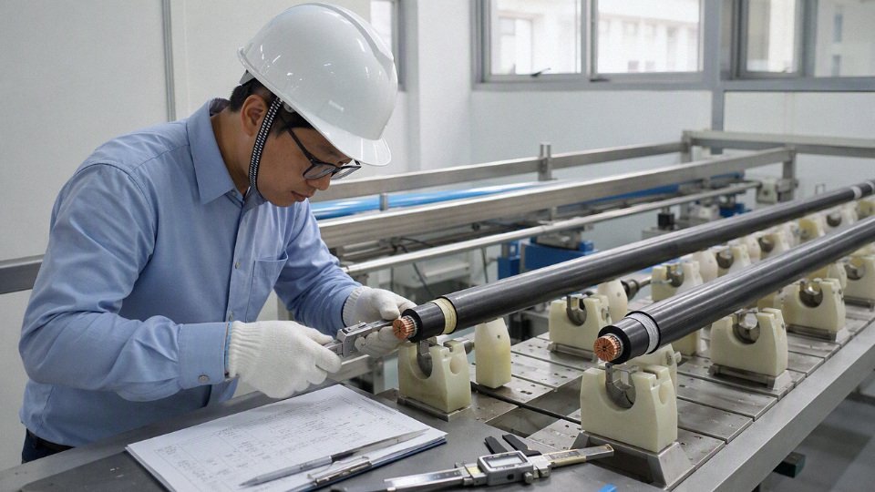
For international projects, early verification saves money in places that are painful to fix later: incompatible terminations, undersized screens, excessive pulling tension, failed document review, unexpected voltage drop, or replacement cable after shipment. Send drawings, load data, installation method, environmental conditions, required standard, expected drum lengths, and destination country before asking for a final price.
Contact Shandong Jinda Special Cable Group Co., Ltd. to review the project specification, compare suitable power cable types, and request a technically aligned quotation for bulk procurement or long-term supply. The more complete the application data, the closer the quotation will be to a cable that installs cleanly, passes review, and performs as intended.