A YY cable often looks like an easy power connection because it is flexible, familiar to panel builders, and already on the shelf. The trouble starts when a control cable is treated like a fixed power feeder without checking current, voltage drop, heat build-up, and protection coordination; then you get nuisance trips, softened PVC, failed terminations, or a machine down on a Monday morning. The right answer is not the cable name alone, but whether that exact YY cable is rated, sized, installed, and protected for the duty.
Yes, a YY cable can be used for power in limited low-voltage applications if its voltage rating, conductor size, temperature limit, installation method, and protective device are suitable. Many YY cables are control cables rated 300/500 V, while some variants may be 450/750 V, so the datasheet must decide the case.
That small “if” is where many buying mistakes happen. A cable that is perfectly acceptable for a short machine interconnect may be the wrong choice for a motor feed in a hot cable tray, a long run with voltage drop, or a grouped installation inside a packed control cabinet.
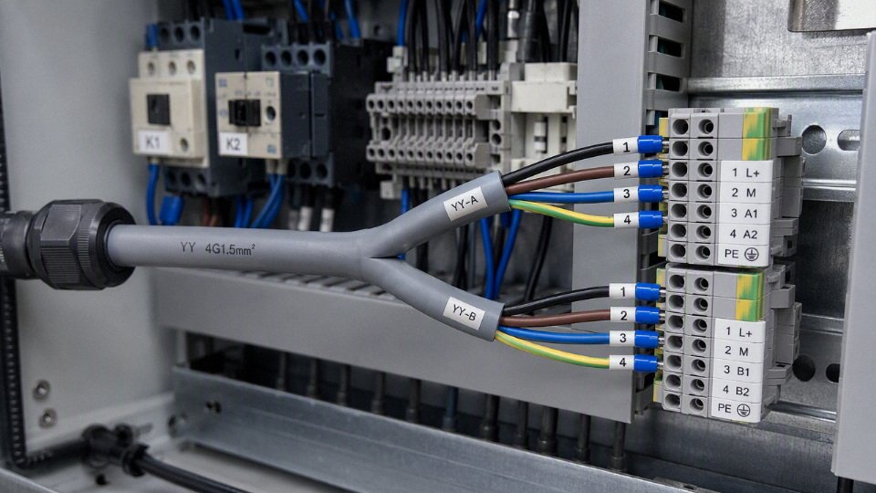
What YY cable is
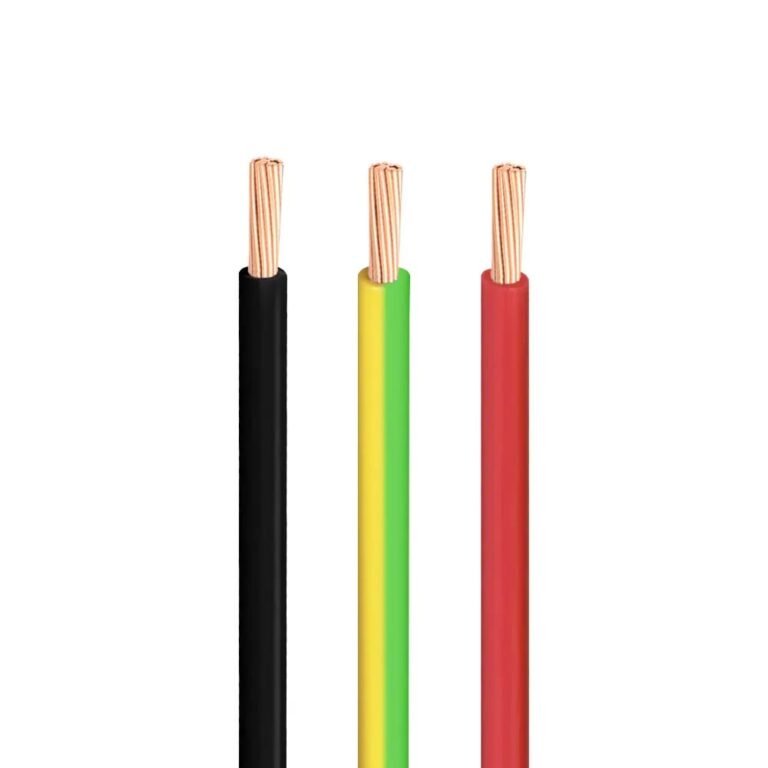
YY cable is a flexible, PVC-insulated and PVC-sheathed multicore industrial control cable, normally built around fine-stranded copper conductors rather than the stiffer conductors used in many fixed power circuits. It looks “power-capable” because it may carry 300/500 V, or sometimes 450/750 V, markings, but its construction is optimized mainly for control, machine wiring, and protected auxiliary circuits.
In practical terms, a typical YY cable has:
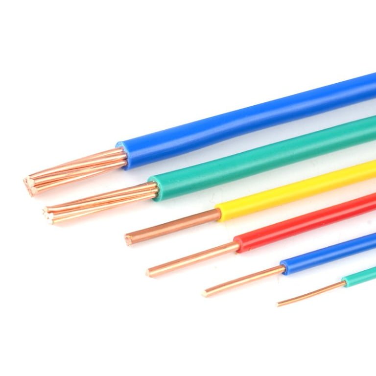
- Plain or tinned copper conductors, usually Class 5 fine-stranded for flexibility and repeated routing inside machinery.
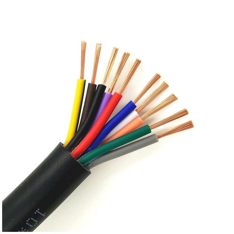
- PVC insulation around each core, with cores identified by numbers, colors, or a green-yellow protective conductor where specified.
- A PVC outer sheath, commonly grey or black, depending on the maker and market.
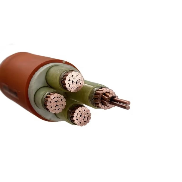
- Multicore layouts, from small 2-core or 3-core cables up to large control bundles with many numbered cores.
      ______________________________________________
     /
    /                PVC outer sheath
   |                                                  |
   |    (1)        (2)        (3)        (4)          |
   |   _____      _____      _____      _____         |
   |  /         /         /         /             |
   | | copper|  | copper|  | copper|  | copper|       |
   | |conductor |conductor|conductor|conductor|       |
   |  _____/    _____/    _____/    _____/        |
   |  PVC insulation around each numbered core         |
                                                    /
     ______________________________________________/
The awkward part is that “YY” is commonly used as an industrial control cable designation, not as one single universal global standard with identical performance everywhere. One supplier’s YY cable may be a basic PVC control cable for indoor machine wiring; another may offer a variant with different voltage rating, conductor class, flame behavior, oil resistance, or approval package. The catalog page and sheath marking matter more than the generic name.
Common voltage classes include 300/500 V for many YY control cables. Some manufacturer-specific variants are marked 450/750 V, but that must be confirmed from the cable printing and datasheet, not guessed from diameter, sheath color, or the fact that the cable has “a decent amount of copper in it.” In a plant, that mistake usually happens when a technician sees a spare multicore on the shelf and treats it like any other low-voltage power cable. The cable may fit the gland and terminate nicely, but rating, installation method, current capacity, and protection coordination still have to be checked.
All YY cables with the same sheath color have the same voltage rating.False
Sheath color and general appearance do not establish voltage class, approvals, oil resistance, UV resistance, or flame performance; those come from the cable marking, datasheet, and certification.
Typical applications for YY cable include:
- Control circuits between panels, sensors, actuators, and machine modules.
- Relay and contactor wiring where currents are modest and circuits are protected.
- Interlock circuits on guards, conveyors, packaging lines, and machine tools.
- Panel-to-machine wiring in dry or protected industrial areas.
- Instrumentation interfaces where shielding is not required.
- Production line equipment wiring where flexible multicore routing saves installation time.
- Light-duty auxiliary power, such as small solenoids, lamps, brakes, or fans, when the cable size, voltage rating, installation conditions, and protective device are suitable.
Its strengths are very practical. Fine-stranded copper makes the cable easier to dress through control panels, drag around machine frames during assembly, and land into terminal blocks without fighting spring pressure. Multicore construction keeps wiring neat, which matters when maintenance has to fault-find a jammed packing line at 2 a.m. Numbered cores also reduce wiring errors in repeated OEM builds. For procurement, YY cable is attractive because the same family can often cover several machine sizes, making bulk buying, stock control, and harness preparation simpler.
The trade-off is mechanical and environmental robustness. YY cable is usually not armored, so it has limited resistance to crushing, forklift contact, dropped tooling, sharp tray edges, or outdoor abuse. Standard PVC control cable temperature limits are often around -15°C to +70°C in normal service, subject to the datasheet; cold stores, hot machine enclosures, welding areas, and roof-level cable runs can push beyond that. PVC can also be a poor choice where oil, coolant, UV, washdown chemicals, or continuous flexing are present unless the exact cable is specified for those conditions.
That is where confusion with power cable becomes risky. A YY cable may be perfectly reasonable inside a guarded machine frame or between a panel and a small motor auxiliary device, yet wrong for a tray run across a factory, a buried feed, an exposed outdoor connection, or a high-load circuit with tight voltage-drop limits. The boundary is not the name “YY”; it is the verified combination of voltage rating, conductor cross-section, current capacity, installation method, ambient temperature, grouping, protective device coordination, and the environment around the cable.
Power use approval conditions
YY cable may be used for power only when the whole installed circuit is proven suitable: voltage rating, current capacity, voltage drop, fault protection, earthing, mechanical protection, and project approval all have to pass together. If one of those checks fails, the cable is not “almost acceptable”; it becomes the wrong cable for that power circuit.
Start with the voltage rating, not the cable name
The first gate is the cable’s rated voltage, usually expressed as U0/U. Common YY control cables are often supplied at 300/500 V, while some manufacturer-specific versions may be rated 450/750 V, but the marking and datasheet decide the answer, not the catalogue family name.
For a simple circuit, the cable rating must be equal to or higher than the actual system voltage between conductor and earth and between conductors. In practice, I would also check:
- Circuit voltage and earthing system: single-phase, three-phase, floating, grounded, or center-tapped systems can stress insulation differently.
- Installation category and transients: long runs near motors, contactors, drives, welders, or inductive loads can see switching spikes that are not obvious from the nominal voltage.
- Local rules and project specifications: a plant standard may require a designated power cable even when a YY cable has a sufficient voltage marking.
- Datasheet test standard: the declared voltage rating should be backed by the applicable cable standard or manufacturer’s documented test basis.
- Cable marking: if the sheath does not clearly show the relevant rating, traceability becomes weak during inspection, maintenance, or accident investigation.
A 300/500 V YY cable may look harmless on a 230 V auxiliary feed, but that does not automatically approve it for every 400 V machine power branch. The safe boundary is the actual installed electrical environment, not the bench condition where the cable was first connected.
A YY cable with the right conductor colors is automatically approved for power wiring.False
Conductor color helps identification, but approval comes from the cable rating, construction, test standard, datasheet, installation method, protective device coordination, and the governing project or local electrical rules.
Current-carrying capacity depends on the installation, not only the conductor size
A YY cable that is electrically insulated for the voltage can still be undersized thermally. The allowable current depends on how fast the conductor generates heat and how easily that heat escapes through insulation, sheath, surrounding air, conduit, trunking, or a crowded cable tray.
The main variables are:
- Conductor cross-section: larger copper area lowers resistance and heat generation for the same current.
- Conductor class: flexible stranded conductors are convenient for moving machine wiring and tight panel work, but current ratings must still come from the relevant table or datasheet, not from a solid-conductor assumption.
- Insulation and sheath temperature limit: common PVC control cables are often around -15°C to +70°C in normal service, subject to the actual datasheet.
- Ambient temperature: a cable inside a hot machine cabinet beside drives and transformers runs warmer than the same cable clipped in free air.
- Grouping: ten loaded multicore cables in a tray do not cool like one isolated cable.
- Enclosure ventilation: sealed control boxes, IP-rated machine frames, and plastic trunking can trap heat.
- Installation method: free air, conduit, cable chain, tray, trunking, wall penetration, and bundled harnesses all change heat dissipation.
The mechanism is simple but unforgiving: conductor resistance creates I²R heat, insulation slows heat escape, and higher conductor temperature increases resistance again. That loop may stabilize at an acceptable temperature, or it may push the PVC close to its limit. Once PVC spends enough time too hot, it hardens, discolors, cracks at bends, and loses the margin that made the installation look safe on day one.
There is a trade-off here. YY cable is attractive because it is flexible, easy to terminate, and neat in machine wiring. Dedicated power cable may be less convenient in a tight panel or moving subassembly, but it often gives better published ampacity data, stronger construction options, and clearer acceptance by inspectors. The preference flips toward YY only where the load is modest, the installation is protected and well ventilated, and the datasheet supports the current after all derating factors.
Do not approve continuous duty from a short test run
A cable that survives a five-minute commissioning test has not proven continuous power suitability. Short tests miss thermal soak, enclosure heat rise, seasonal ambient changes, and the effect of several circuits running at the same time.
Separate the load profile before signing off the cable:
| Load pattern | What to check | Typical risk if ignored |
|---|---|---|
| Continuous load | Full-load current for the whole operating shift, derated for ambient and grouping | Slow overheating, insulation aging, nuisance trips later in summer |
| High duty-cycle intermittent load | RMS heating effect over the duty cycle, not only peak current | Cable passes jogging tests but overheats during production |
| Short inrush load | Starting current duration and voltage drop | Motor contactor chatter, weak solenoid pull-in, supply dips |
| Occasional service load | Frequency of use, operator behavior, locked-rotor or stalled condition | “Temporary” functions become regular production loads |
| Heater load | Steady current, enclosure temperature, terminal temperature | Hot terminals and brittle insulation near the gland or ferrule |
This is where maintenance history matters. If operators routinely leave a heater circuit energized through breaks, or a small pump that was meant for purge duty now runs half the shift, the original intermittent assumption is gone. I have seen plenty of “only for testing” feeds become permanent because the machine kept running and nobody wanted to reopen the job.
Voltage drop must be checked on power and control-related loads
Voltage drop is not only a long-distance building wiring issue. Machine runs, moving gantries, heater banks, solenoids, DC supplies, and small motors can all misbehave if the cable resistance is too high for the load and length.
Check voltage drop especially for:
- Motors: poor starting torque, longer acceleration, contactor chatter, or drive undervoltage alarms.
- Heaters: lower wattage output and slow heat-up, which may look like a process problem rather than a wiring issue.
- Solenoids and brakes: weak pull-in, buzzing coils, delayed release, or overheating from partial engagement.
- Long machine runs: voltage may be acceptable at the panel and unacceptable at the actuator.
- Low-voltage AC or DC control supplies: a few volts lost on a 24 V circuit can be a large percentage of the available voltage.
The trade-off is conductor cost and bendability. Increasing conductor size reduces voltage drop and heat, but it makes the cable larger, stiffer, harder to gland, and harder to route through existing machine frames. On a retrofit, the correct engineering answer may be a larger cable, a local power supply, a different routing path, or splitting loads rather than forcing an oversized multicore through a crowded drag chain.
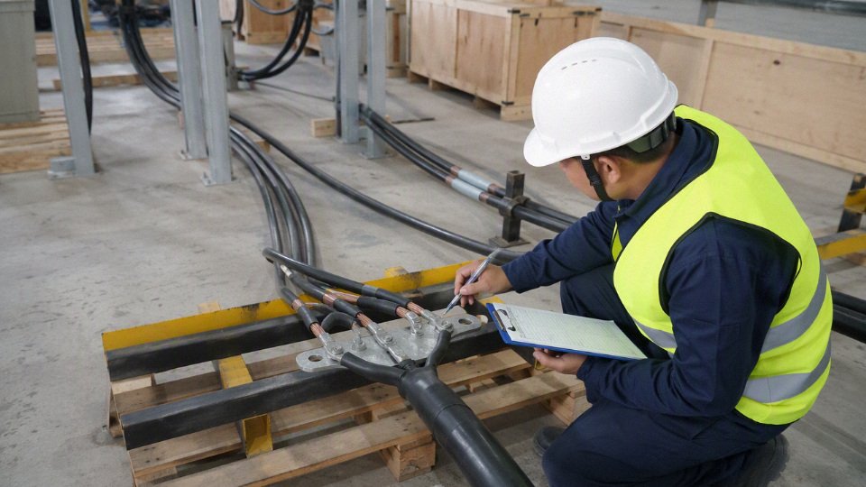
Protective devices must actually protect the YY cable
A fuse or circuit breaker protects the cable only if its rating and operating curve suit the installed conductor and fault conditions. It is not enough that “there is a breaker upstream.” The protective device must disconnect overloads before the conductor overheats and clear short circuits within the required time for the applicable system.
Verify at least these points:
- Overload protection: the breaker or fuse rating should not exceed what the cable can carry after derating for the actual installation.
- Short-circuit protection: prospective fault current and disconnection time must be suitable for the conductor size and insulation.
- Device curve: motor circuits and transformer inrush may need different characteristics than a simple resistive load.
- Coordination with downstream devices: a small YY-fed branch should not rely on a large upstream feeder breaker that cannot protect the smaller conductor.
- Terminal ratings: loose ferrules, undersized terminals, or mixed conductor types can become the hottest point even if the cable itself is acceptable.
Protective device coordination is where casual substitutions often fail. A small multicore YY cable tapped from a larger machine supply may energize the load perfectly, but under fault conditions the upstream breaker may be sized for the main feeder, not the smaller branch. That is not a paperwork problem; it is a fire-risk problem.
Earthing and protective conductor requirements cannot be assumed
If the YY cable includes a green/yellow protective earth core, confirm that its size, continuity, and termination method are suitable for the circuit. If the cable does not include a suitable protective conductor, a separate protective conductor may be required by the installation rules or project specification.
The check should include:
- Protective earth core cross-section versus phase conductor size and fault duty.
- Continuity through plugs, glands, terminal blocks, moving sections, and junction boxes.
- Suitability of ferrules, lugs, and earth bars for fine-stranded flexible conductors.
- Bonding of metallic machine frames, motor housings, and enclosures.
- Inspection access after covers, guards, or cable carriers are installed.
Do not use a spare numbered core as a casual earth substitute unless the governing rules permit it and the conductor is correctly identified and terminated. Inspectors tend to notice that, and so do competent maintenance electricians.
Mechanical protection is part of electrical approval
YY cable is generally more defensible inside protected environments: panels, enclosed trunking, conduits, machine frames, control cabinets, protected cable trays, or short internal equipment links. It becomes much harder to justify where the cable is exposed to crushing, abrasion, oil-soaked dragging, forklift contact, sharp sheet-metal edges, weld spatter, or repeated flexing beyond its design.
Suitable mechanical arrangements may include:
- Enclosed control panel wiring with proper gland plates and strain relief.
- Fixed machine wiring inside guarded frames or covers.
- Protected tray routes away from traffic and sharp edges.
- Conduit or trunking where impact or abrasion is credible.
- Correct bend radius and clamping so the termination is not carrying cable weight.
If the route crosses a shop-floor walkway, hangs behind a machine where pallets get pushed, or passes near hot tooling, a standard YY control cable is usually the wrong first choice. The electrical numbers may still pass, but the mechanical environment will decide the service life.
Regulatory and project approval may overrule the calculation
Even when voltage, current, voltage drop, protection, earthing, and mechanical routing look acceptable, the cable still has to satisfy the authority having jurisdiction and the contract documents. IEC-based projects, European specifications, British practices, Middle Eastern oil and gas requirements, African mining sites, Asian industrial parks, and owner-specific plant standards may not treat YY cable the same way.
The approval file should normally include:
- Cable datasheet and construction details.
- Sheath marking or batch traceability.
- Rated voltage and temperature range.
- Referenced test standard or manufacturer declaration.
- Installation method and derating basis.
- Load current and voltage drop calculation.
- Protective device type, rating, and curve.
- Earthing arrangement.
- Any client, consultant, insurer, or local authority requirement.
Cable color, multicore format, or the fact that a cable “looks like the one used before” is not approval evidence. The governing documents are the datasheet, cable marking, relevant standard, installation calculation, and project specification. Where those documents conflict, the stricter requirement usually wins unless the responsible engineer and approving authority accept a documented deviation.
Unsafe YY cable locations
YY cable should normally be rejected wherever the cable is expected to provide environmental protection, mechanical protection, certified fire behavior, or drive-output performance beyond a light-duty control cable. If the installation needs armor, UV-rated sheath, oil resistance, washdown approval, low-smoke performance, or VFD output suitability, standard YY cable is usually the wrong starting point. The exception is only a manufacturer-specific YY variant with documented ratings for that exact duty.
A YY cable voltage rating alone is enough to approve it for power use.False
Voltage rating is only one check. The installation must also satisfy current capacity, voltage drop, protective device coordination, temperature, mechanical protection, environmental exposure, fire requirements, and any local code or project specification.
The failures I worry about are not always immediate. A cable can energize a small motor or heater on day one and still be a poor installation. Six months later the sheath has gone hard near hot pipework, the insulation has wicked moisture at an outdoor gland, or a forklift has flattened the cable under a pallet leg. By then the breakdown has become a production fault, not a design discussion.
| Location or condition | Hidden hazard | Likely failure mode | Safer cable choice |
|---|---|---|---|
| Direct burial | Soil moisture, compaction, stones, soil chemicals, rodents, no visual inspection | Sheath cracking, water ingress, earth fault, crushed cores | Armored or direct-burial-rated power/control cable in suitable duct or trench system |
| Outdoor ground runs | UV, standing water, ice, impact from tools or vehicles | Brittle sheath, damaged insulation, nuisance trips | UV-resistant outdoor cable, armored cable, or cable in mechanical conduit/tray with drainage |
| Unprotected external routing | Ladders, maintenance traffic, wind movement, sharp brackets | Abrasion, cut sheath, intermittent faults | Outdoor-rated flexible cable with protection, steel conduit, covered tray, or armored cable |
| Crane routes and moving equipment paths | Repeated flexing, tensile load, twisting, impact | Broken conductors, hot joints, insulation fatigue | Festoon cable, reeling cable, drag-chain cable, or rubber flexible cable designed for motion |
| Forklift and production floor zones | Crush loads, pallet damage, swarf, coolant, foot traffic | Flattened cores, sheath cuts, short circuits | Armored cable, protected tray, floor trench, overhead drop, or heavy-duty flexible cable |
| Sharp edges and vibrating machinery | Micro-movement against metal, loose clips, burrs | Sheath wear-through, earth leakage, conductor fracture | Properly clamped industrial cable, abrasion-resistant sheath, grommets, strain relief |
| Wet, oily, chemical, or washdown areas | Fluid absorption, detergent attack, pressure spray, capillary ingress at glands | Swollen sheath, tracking, corrosion, insulation resistance collapse | Cable with confirmed oil/chemical/water resistance and suitable IP-rated glands |
| High-temperature areas | PVC insulation and sheath temperature limit exceeded, poor heat dissipation | Hardening, deformation, insulation embrittlement, reduced life | Heat-resistant cable, silicone, XLPE, glass-braid, or routed thermal separation |
| Fire-performance-critical routes | Smoke toxicity, flame spread, circuit failure during fire | Non-compliance, unsafe smoke generation, loss of emergency function | LSZH, flame-retardant, fire-resistant, or circuit-integrity cable as specified |
| VFD motor outputs | High dV/dt pulses, common-mode current, EMC emissions, harmonic heating | Motor bearing current, drive trips, insulation stress, noise on instruments | Screened VFD motor cable with proper grounding and drive-approved construction |
| Public infrastructure and building distribution | Certified wiring systems and inspection requirements | Rejection by inspector, insurance issue, unsafe installation | Code-approved building wire, power cable, armored cable, or specified listed cable |
| Hazardous areas | Gas, vapor, dust ignition risk, gland certification | Non-compliant ignition source pathway | Hazardous-area-certified cable system and glands per zone/classification |
| Emergency systems and safety circuits | Required survivability or documented fire behavior | Loss of safety function during incident | Certified fire-rated or safety-system cable specified by design authority |
| Breakdown “temporary” substitution | No calculation, no labels, undocumented change | Overload, wrong protection, permanent unsafe shortcut | Approved replacement cable after sizing, inspection, labeling, and sign-off |
Direct burial is the first hard no in most plants. Standard YY cable is not normally built to resist long-term soil pressure, stones, water, or underground chemical exposure. Even if the load current is modest, the soil environment changes the job: the sheath becomes the primary environmental barrier, and a general PVC control sheath is a weak barrier compared with a proper buried cable system.
Outdoor routing has a similar trap. A cable clipped neatly along a wall can look acceptable during commissioning, then fail after UV exposure, winter contraction, and water sitting at a low gland. In practice, the weak points are often ordinary accessories: a cheap compression gland without the right seal, a cable tie pulled too tight, or a tray edge that moves in the wind. If the run is outside, specify the outdoor exposure and mechanical protection, not just conductor size.
Heavy mechanical areas are where YY cable gets abused because it is flexible and easy to pull. That flexibility is not the same thing as suitability for repeated flexing, dragging, torsion, or crush. A drag chain needs cores, fillers, lay length, sheath material, and bend radius designed for continuous motion. A crane festoon needs tensile management. A cable crossing a production floor needs protection from forklifts, pallet trucks, scrap bins, and the maintenance habit of “just set it there for five minutes.”
Wet and oily duty needs more than a casual “PVC is fine” assumption. Coolant mist, hydraulic oil, food-cleaning foam, caustic wash, solvents, and disinfectants do not attack every sheath in the same way. Some fluids soften the sheath; others creep through glands and junction boxes, then lower insulation resistance days later. If a datasheet does not identify resistance to the actual fluid and exposure method, treat it as unapproved. Spray exposure, immersion, vapor, and occasional wipe-down are different service conditions.
Temperature is another quiet derating problem. Common PVC control cables are often around -15°C to +70°C in normal service, but the exact limit must come from the cable datasheet. A cable near an oven, heater band, furnace wall, steam pipe, motor frame, braking resistor, or packed control cabinet may see a local sheath temperature far above the room temperature. Once PVC ages hard, it does not become young again after the plant cools down.
Fire requirements can override every electrical calculation. In public buildings, tunnels, rail, process plants, high-rise risers, escape routes, emergency lighting, fire alarm, smoke control, and safety shutdown circuits, the cable may need verified flame spread, smoke, halogen, fire-resistance, or circuit-integrity performance. A standard YY cable should not be substituted into those routes unless the project specification and local authority accept that exact cable construction.
Motor drives deserve separate caution. A VFD output is not a clean 50/60 Hz supply; it is a pulsed waveform with steep voltage edges. Cable capacitance, screening, grounding geometry, conductor symmetry, and termination method all affect drive stress, electromagnetic noise, bearing currents, and nuisance tripping. A short, lightly loaded run may appear to work, but longer runs and higher carrier frequencies can expose the wrong cable quickly. Use the drive manufacturer’s cable guidance and a purpose-designed screened motor cable where required.
The messiest cases are temporary repairs. Someone uses spare YY cable during a breakdown, the line restarts, the shift is grateful, and the “temporary” run survives until it is forgotten. If it stays, it needs to be treated like a new installation:
- Recalculate current capacity, voltage drop, grouping, ambient temperature, and protective device coordination.
- Inspect the route for heat, oil, abrasion, impact, bend radius, and gland sealing.
- Confirm the cable datasheet supports the service conditions.
- Replace with the proper cable if any requirement is not met.
- Label the circuit and update drawings, maintenance records, and approval documents.
The boundary is simple enough: YY cable can be acceptable only where the environment is controlled, mechanical risk is low, temperature stays within the datasheet, and no special fire, EMC, hazardous-area, or certification requirement applies. Once the cable itself is being asked to act as armor, weather barrier, fire system component, or VFD engineering control, upgrade the cable rather than hoping careful installation will compensate.
YY versus power cables
YY cable should be treated as a flexible control and light interconnection cable first, not as the default answer for every circuit that carries voltage. For feeders, distribution runs, outdoor equipment, buried routes, impact-prone areas, or project-specified installations, a proper power, armored, rubber flexible, tray, or instrumentation cable is usually the safer and easier-to-approve choice.
A common buying mistake is to reduce the decision to voltage rating and core count: “It is 300/500 V, the motor is small, so use it.” That misses the plant-floor issues that actually decide whether the cable survives: clamp pressure, tray fill, oil mist, sunlight at the dock door, vibration at a pump skid, water sitting in a cable gland, and whether the inspector or client specification recognizes that cable type for the installation.
YY compared with standard fixed power cable
Standard fixed power cable is normally selected for feeder and distribution circuits where the installation is expected to stay in place for years, carry higher current, and coordinate cleanly with protective devices. Compared with YY, a fixed power cable usually gives the engineer a clearer route through cable schedules, electrical codes, gland selection, short-circuit withstand checks, and site inspection.
YY can be convenient inside machinery, control panels, short interconnections, or low-current auxiliary supplies where flexibility and multicore control wiring matter. The trade-off is that its sheath and installation category may not match the abuse level of a plant distribution circuit. If the run leaves the machine envelope and becomes part of building power distribution, the preference usually flips toward a recognized fixed power cable.
YY compared with NYY-type cable
NYY-type cable is typically associated with fixed low-voltage power distribution. Exact construction and approvals vary by manufacturer and market, but the family is generally understood as a power cable with solid or stranded copper conductors, PVC insulation, and a more robust outer sheath suited to fixed installation duties.
YY is different in intent. It is usually a flexible PVC control cable for control signals, interlocks, instrumentation-style wiring, and light power within equipment limits. A buyer may see both products offered with similar voltage markings and assume they are interchangeable. They are not. The mechanism is simple: the sheath compound, conductor class, installation approval, and intended fixing method all affect heat dissipation, mechanical damage resistance, and long-term compliance. A cable that behaves well in a cabinet wireway may be a poor choice clipped along a warehouse wall where forklifts, ladders, and maintenance contractors live.
YY compared with armored cable such as steel wire armored cable
Armored cable, including steel wire armored types, earns its keep where external damage is a credible risk. That includes direct burial where permitted by the cable design and local rules, exposed runs on industrial structures, yard lighting, pump stations, utility areas, and long routes where nobody can promise the cable will remain untouched.
YY has no equivalent armor layer. A PVC sheath can resist normal handling and routing, but it is not a substitute for steel wire armor, conduit, trunking, or other mechanical protection. In procurement terms, armored cable costs more and is slower to terminate, but it can reduce the hidden cost of nuisance trips, insulation damage, emergency shutdowns, and arguments over who hit the cable. On dirty sites, I would rather pay for the right protection than rely on a neat drawing that assumes the installation will stay neat.
YY compared with rubber flexible cable such as H07RN-F
Rubber flexible cables such as H07RN-F are often the better answer for portable equipment, outdoor temporary power, wet areas, workshops, construction-type duty, and mechanically demanding applications. They are designed around movement, abrasion, moisture exposure, and tougher handling than a typical PVC control cable.
YY may bend nicely during installation, but that does not make it a trailing cable. PVC can stiffen in cold conditions, soften near heat sources, and suffer where oil, UV exposure, or repeated dragging are present unless the specific datasheet says otherwise. Common PVC control cable limits are often around -15°C to +70°C in normal service, but the actual figure must come from the manufacturer’s datasheet. If operators unplug equipment every shift, drag it across concrete, wash nearby floors, or leave coils outdoors, rubber flexible cable is usually the more honest specification.
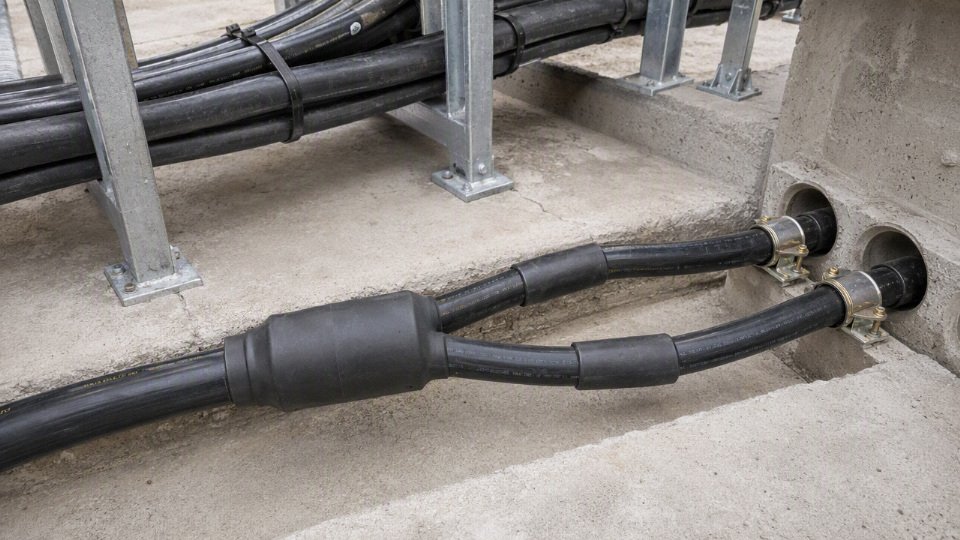
YY compared with CY and SY control cables
CY and SY sit closer to YY than the heavy power cable families do, but they solve different problems.
- CY control cable adds a metallic screen, commonly used where electromagnetic interference may disturb signals or where control wiring runs near drives, contactors, servo cables, or other noise sources. The screen only works properly if terminated and earthed according to the design; a floating screen can become an expensive decoration.
- SY control cable adds a steel wire braid for improved mechanical protection compared with YY. It is useful in machine wiring and industrial interconnections where scuffing or light mechanical exposure is expected, but it should not be confused with full armored power cable.
- Power use still needs verification. Some markets and project specifications restrict or reject SY, CY, or YY for certain fixed power applications regardless of conductor size. Do not assume that because a control cable has a braid or screen it becomes a compliant power cable.
This is where purchasing language causes trouble. “Screened,” “braided,” and “armored” are not interchangeable words. A CY screen is mainly for electromagnetic performance; an SY braid improves mechanical robustness; steel wire armor is a much heavier protection system used in power distribution contexts. The right choice depends on the failure mode you are trying to prevent.
YY compared with tray cable and instrumentation cable
Tray cable and instrumentation cable are often specified because a project needs more than copper cores inside a sheath. The requirement may involve flame propagation tests, sunlight resistance, oil resistance, low-smoke performance, pair twisting, individual and overall screens, drain wires, numbered pairs, or an installation approval for cable tray use.
YY should not be forced into those duties just because it is available in many core counts. For example, an analog signal from a transmitter beside a variable frequency drive may need twisted screened pairs, not just spare YY cores. A cable tray in a petrochemical or utility project may require a defined flame test and printed approval marking. A wastewater plant may need UV and moisture performance that ordinary indoor PVC control cable was never bought to provide.
Comparison table for practical selection
| Cable family | Primary purpose | Mechanical protection | Electromagnetic protection | Typical environment | Power suitability | Procurement caution |
|---|---|---|---|---|---|---|
| YY control cable | Flexible control, interconnection, light auxiliary circuits | Low to moderate, depending on sheath and routing | None unless separately specified | Panels, machines, protected indoor routes | Limited, only after load, voltage drop, installation, and approval checks | Do not buy on voltage rating alone |
| Standard fixed power cable | Feeders, subcircuits, distribution wiring | Moderate, depending on sheath and installation method | Usually none | Buildings, fixed plant wiring, cable tray or conduit as approved | Stronger fit for general power distribution | Match to local code, current rating, installation method, and protective device |
| NYY-type cable | Fixed low-voltage power distribution | Generally more robust than YY | Usually none | Fixed indoor/outdoor routes where the cable type is accepted | Typically a better fit than YY for fixed power | Verify national standard, UV/burial suitability, and conductor class |
| Steel wire armored cable | Power in exposed, buried, or damage-prone routes | High | Usually none unless combined with screening | Industrial yards, buried routes, exposed plant areas | Strong fit where mechanical risk is high | Termination skill, gland type, bending radius, and earthing must be planned |
| H07RN-F or similar rubber flexible cable | Portable and flexible power | Good for handling and abrasion | Usually none | Outdoor equipment, workshops, wet or temporary duty | Good fit for portable power within rating | Check oil, chemical, temperature, and duty-cycle exposure |
| CY control cable | Screened control wiring | Similar to YY unless construction differs | Good when screen is correctly terminated | Noisy electrical environments, automation systems | Conditional and specification-dependent | Confirm screen construction, earthing method, and acceptance for the circuit |
| SY control cable | Control wiring with steel wire braid | Better than YY, below true armored cable | Limited unless also screened | Machine interconnections, light industrial exposure | Conditional and locally sensitive | Do not treat braid as equivalent to power cable armor |
| Tray or instrumentation cable | Project-specified tray, signal, or process wiring | Varies by design | Often screened, paired, or shielded | Process plants, utilities, cable trays, instrumentation systems | Depends on listing and construction | Buy to the project specification, not just core count and voltage |
A thicker-looking cable is not automatically safer. I have seen oversized flexible cables fail early because the sheath was wrong for oil exposure, the conductor temperature rating did not suit the load grouping, or the cable had no approval for the installation route. Visual diameter can reflect filler, sheath thickness, conductor class, or core count; it does not prove current capacity, flame performance, UV resistance, short-circuit behavior, or code acceptance.
A YY cable with the same voltage rating and conductor size as a power cable is automatically equivalent for power distribution.False
Voltage rating and conductor cross-section are only part of the selection. The cable construction, sheath material, temperature rating, installation method, mechanical protection, approvals, grouping, voltage drop, and protective device coordination also have to be checked.
For procurement, the better question is not “Can one cable cover everything?” It is “Which cable family removes the most technical and approval risk for this route?” YY may be perfectly sensible inside a protected machine circuit. Once the cable becomes a feeder, an outdoor run, a tray-installed project cable, a portable lead, a screened signal path, or a mechanically exposed supply, another cable family often becomes the more defensible purchase.
Sizing and protection checks
Use this workflow before issuing a YY cable on a purchase order or releasing it to an electrician. The cable type may already be acceptable in principle, but the circuit still has to pass current, voltage-drop, fault-withstand, protection, termination, and installation checks.
- Identify the actual load, not just the machine nameplate
Collect the circuit data before selecting a conductor size:
- Supply voltage and tolerance, such as 230 V single-phase or 400 V three-phase.
- Phase arrangement and number of loaded conductors.
- Full-load current from the load datasheet or measured running current on a comparable machine.
- Starting current for motors, compressors, pumps, solenoids, heaters with cold resistance, and transformer-fed loads.
- Inrush current for switch-mode power supplies, VFD input capacitors, contactor coils, LED drivers, and control transformers.
- Power factor, especially on motor and transformer circuits.
- Duty cycle: continuous, intermittent, cyclic, or standby with short high-current events.
- Operating hours and expected ambient temperature during production, not during a clean morning inspection.
- Future capacity margin, if the machine builder expects extra valves, heaters, sensors, or cabinet auxiliaries later.
A common mistake is sizing from “normal running amps” while ignoring a load that starts ten times per hour. The copper may survive the average current, but the protective device may nuisance-trip, terminals may loosen through thermal cycling, or the voltage dip may reset a PLC power supply.
- Select conductor cross-section from allowable ampacity
Start with the allowable current-carrying capacity from the applicable wiring standard, local electrical code, or the YY cable manufacturer’s datasheet. Do not lift a current value from a random catalogue table unless the installation conditions match your job.Check these inputs before accepting the size:
- Conductor material, usually copper for YY control cable.
- Cross-sectional area, such as 0.75 mm², 1.0 mm², 1.5 mm², 2.5 mm², or larger where offered.
- Number of loaded cores inside the cable.
- Installation method: free air, tray, conduit, trunking, machine frame, cabinet duct, or energy chain.
- Ambient temperature around the cable.
- Grouping with other loaded cables.
- Cable temperature rating, often around -15°C to +70°C for common PVC control cable in normal service, subject to the actual datasheet.
Voltage rating, commonly 300/500 V for many YY cables, with some manufacturer-specific variants rated 450/750 V.
The mechanism is simple but unforgiving: current creates heat by I²R losses, and insulation life drops as conductor temperature rises. Grouping, conduit fill, cabinet heat, and poor ventilation reduce heat rejection, so a cable that is comfortable on an open bench can run too hot inside a packed control panel in July. Ampacity is not a property of the cable alone; it is a property of the cable in a specific installation.
The trade-off is between cable size, flexibility, panel space, and cost. Upsizing from 1.0 mm² to 1.5 mm² may reduce heat and voltage drop, but it also increases bend radius, gland size, terminal crowding, and drum weight. The preferred choice flips when the installation is moving, tightly routed, or terminated into small device terminals that are not approved for the larger conductor.
Check voltage drop under operating and starting conditions
Voltage drop needs the circuit length, load current, conductor resistance, supply voltage, and allowable drop for the equipment. For longer runs or three-phase motor feeds, include reactance where it is relevant; for short machine wiring it is often small compared with resistance, but that assumption should not be made blindly on long routes.Check voltage drop separately for:
- Motors, where excessive drop reduces starting torque and increases current.
- Control transformers and PLC power supplies, where dips may cause resets or contactor chatter.
- Lighting, where the issue may be brightness, driver stability, or nuisance flicker.
Auxiliary sockets or service outlets, where unknown future loads can become the real problem.
In practice, voltage-drop acceptance depends on the equipment and the site rule. A small fan motor may tolerate more drop than a sensitive 24 V DC power supply fed through a transformer. If the load has a manufacturer limit for input voltage during start or operation, that limit overrides a comfortable rule of thumb.
- Verify short-circuit withstand
A cable must survive long enough for the protective device to clear a fault. Check:
- Prospective fault current at the point of installation.
- Protective device type and clearing time at that fault level.
- Conductor material.
- Conductor cross-sectional area.
- Insulation thermal limit from the cable data.
Whether the fault is line-to-line, line-to-neutral, or line-to-earth.
For small YY conductors fed from a large upstream breaker, this is where designs often fail. A 0.75 mm² or 1.0 mm² auxiliary cable may be connected downstream of a panel supply protected at a level chosen for the whole machine, not for that small branch. If the downstream fuse or miniature circuit breaker is omitted, the cable can become the weak link during a fault.
A YY cable that passes normal running current can still be unsafe if the upstream protective device cannot clear a fault before the conductor insulation is thermally damaged.True
Running ampacity and short-circuit withstand are different checks. Fault current heating is severe and brief, so it must be assessed against protective-device clearing time and the cable conductor and insulation limits.
- Coordinate overload and short-circuit protection
The breaker or fuse must protect the cable, not just the machine. Confirm that:
- The protective device rating does not exceed the corrected cable ampacity.
- The trip curve allows normal starting or inrush without nuisance operation.
- The device clears short circuits fast enough for the selected conductor.
- Downstream branch circuits with smaller conductors have their own protection.
- Control circuits fed from transformers or power supplies are protected on the secondary side where required.
- The disconnection method meets the applicable electrical code and machine safety requirements.
This is a commercial issue as much as an electrical one. A buyer may try to standardize one cable size across a project to simplify purchasing, but protection coordination can force different branch sizes or local fusing. Standardization is useful only until it hides an unprotected small conductor.
- Check termination compatibility
Fine-stranded flexible conductors behave differently from solid or coarse-stranded power cable conductors. Before approving the cable, verify the termination system:
- Ferrules for screw-clamp terminals where required or good practice.
- Correct crimp lugs for stud terminals and earth bars.
- Terminal approval for fine-stranded conductors.
- Proper stripping length, especially on compact terminal blocks.
- Torque values from the device or terminal manufacturer.
- Strain relief so vibration is not carried by the copper strands.
- Gland selection for sheath grip and ingress protection.
Hot joints usually start small: one loose strand, an over-stripped conductor, a ferrule crushed with the wrong die, or a maintenance electrician reusing a terminal after a rushed weekend repair. Infrared inspection later may find the symptom, but correct termination prevents the fault.
- Confirm neutral and protective earth sizing
Do not assume the neutral and protective earth can be treated as spare conductors. Check:
- Single-phase loads returning through a shared neutral.
- Unbalanced three-phase auxiliary circuits.
- Harmonic-producing loads, including switch-mode power supplies and LED drivers.
- Control transformers with secondary bonding arrangements.
- Protective earth continuity through glands, panels, moving machine sections, and removable assemblies.
Local rules for minimum protective conductor size and identification.
Harmonics are the awkward one. In some circuits, neutral current can be higher than expected even when phase currents look acceptable. If several single-phase electronic loads are bundled into one multicore cable, ask for actual load details rather than assuming a balanced three-phase condition.
- Account for enclosure and routing heat
A YY cable routed inside a cabinet, conduit, drag chain, or cable tray bundle may need derating. Look at the actual route:
- Cabinet ducts packed above VFDs or power supplies.
- Tray sections exposed to sun or warm roof spaces.
- Conduit runs with several loaded cables and little air movement.
- Energy chains where flexing, crowding, and heat combine.
Cables tied tightly to hot machine frames, ovens, heaters, or hydraulic power packs.
The boundary of any desktop sizing result is the assumed installation environment. Once the cable is moved into a hotter, more crowded, or more flexible route than assumed, the calculation must be revisited.
Worked example outline: small machine auxiliary feed
A practical approval file for a small auxiliary feed might look like this:
| Check step | Example input | What to verify | Accept or reject logic |
|---|---|---|---|
| Load definition | 230 V single-phase auxiliary circuit, running current 4.2 A, short inrush from a small power supply and contactors | Confirm full-load current, inrush, duty cycle, and any future spare load | Reject if the “spare” load is undefined but expected to feed heaters or sockets |
| Cable rating | YY cable datasheet shows suitable voltage rating for the circuit | Voltage rating must match the system and installation category required by the project | Reject if only a lower-rated cable is available |
| Ampacity | Proposed conductor size checked against standard table and manufacturer data | Apply installation method, ambient temperature, loaded cores, and grouping factors | Accept only if corrected ampacity remains above design current and protective device rating |
| Voltage drop | Use route length there and back for single-phase calculation, conductor resistance at operating temperature, and load current | Compare operating drop and inrush dip against equipment tolerance | Upsize or shorten route if PLC supply, contactor, or auxiliary device may drop out |
| Derating | Cable passes through cabinet duct with other loaded cables | Apply grouping and enclosure temperature correction | Reject the first size if corrected rating falls below required current |
| Protection | Local miniature circuit breaker or fuse installed for this branch | Device rating and trip curve protect the conductor while tolerating inrush | Reject if the branch relies only on a large upstream machine breaker |
| Termination | Fine-stranded cores into terminal blocks | Use ferrules, correct strip length, and terminal torque | Reject loose bare-strand termination in screw terminals not approved for it |
| Final decision | All checks documented | Cable, route, protection, and terminations treated as one system | Approve only with the stated installation conditions on the drawing or purchase specification |
For procurement, the purchase line should not say only “YY cable, 3 core, 1.5 mm²” if the engineering decision depends on rating, sheath material, flexibility class, temperature limit, approvals, or manufacturer datasheet values. Put the minimum voltage rating, conductor size, number of cores, sheath requirements, applicable standard or approval requirement, and any project-specific test or documentation requirement into the RFQ. That prevents a low-priced substitute from arriving on site that looks right on the reel but fails the calculation.
Installation and procurement controls
A technically acceptable YY cable can still fail early if it is installed like scrap flex or bought against a vague line item such as “control cable, PVC, 12 core.” For power use, the two weak points are usually field handling and purchasing ambiguity: one damages the insulation system, the other delivers a cable that was never matched to the duty.
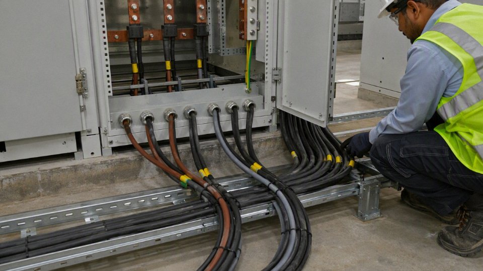
Installation controls that protect the cable before it is energized
YY cable is relatively easy to route, which is exactly why crews sometimes abuse it. The damage is not always visible on day one; a tight bend, crushed sheath, or nicked outer jacket can become a hot spot after load current, vibration, oil mist, and seasonal temperature swings have done their work.
Use the project cable schedule and manufacturer datasheet to control these points on site:
- Minimum bend radius: Follow the cable datasheet, especially at panel entry, drag-free loops, and tray drops. Do not let installers “dress” the cable tightly around DIN rail corners just because it looks neat.
- Sharp-edge protection: Fit edge strip, bushings, conduit glands, or proper tray drop-outs where the cable passes through sheet metal. A punched enclosure hole without deburring is a common source of sheath cuts.
- Strain relief: Do not leave terminal screws carrying cable weight. Use cable glands, clamps, tie bars, or cleats so vibration and pulling force are taken by the support system, not by the conductor termination.
- Suitable glands: Match gland size to the cable outside diameter and sheath type. Over-tightening a cheap nylon gland can ovalize the cable; under-tightening loses sealing and strain relief.
- Sheath damage control: Reject cable with exposed insulation, deep scoring, flattened sections, or chemical swelling. Taping over jacket damage is a temporary maintenance trick, not an installation standard.
- Heat and moving parts: Keep YY cable away from motor frames, heaters, steam lines, chains, cylinders, and guarding hinges unless the design specifically allows for temperature, movement, and abrasion.
- Proper support: Use tray, conduit, cleats, or cable ties at sensible intervals. Avoid tight tie-wraps; they can indent PVC and make troubleshooting harder later.
The trade-off is simple: tighter routing saves tray space and looks clean, but it increases mechanical stress and future maintenance risk. In practice, a slightly longer, better-supported route usually costs less than one nuisance fault inside a packed cabinet during production.
Electrical workmanship, segregation, and route discipline
Termination quality decides whether the calculated current rating survives contact with the machine. Use ferrules for fine-stranded conductors where the terminal design expects them, and use the correct lug type for stud or busbar connections. Torque terminals to the device manufacturer’s data, not to the electrician’s wrist memory; I have seen loose terminals pass commissioning and then brown the insulation six months later.
For multi-core YY cable, control the wiring identity from the start:
- Fit permanent core labels or heat-shrink markers before termination.
- Maintain earth continuity through the protective conductor and bonding path.
- Check polarity before energizing DC loads, solenoids, and control transformers.
- Do not mix power cores and sensitive analog, encoder, load cell, Ethernet, or communication cores unless interference has been assessed.
- Keep spare cores identified and safely parked, not cut back randomly inside the gland plate.
Segregation is not paperwork; it prevents faults that are hard to prove. Route power, control, instrumentation, network, and VFD circuits separately where required by the equipment design, local practice, or electromagnetic compatibility needs. VFD output cables are a particular concern because high switching edges can couple noise into adjacent circuits; if those circuits share a tray with low-level signals, the first symptom may look like a bad sensor, not a cable routing error.
Inspection and testing before handover
Use a short, written test record. It gives maintenance a baseline and stops arguments between purchasing, installation, and commissioning teams when a fault appears.
Received cable and pre-installation inspection checklist:
- Confirm cable type matches the purchase order and datasheet.
- Check voltage rating, conductor cross-section, number of cores, and conductor class.
- Verify sheath material, color, marking, and any required flame rating.
- Confirm temperature range and any specified oil, chemical, or UV resistance.
- Inspect drum condition, end caps, wrapping, moisture protection, and transit damage.
- Check drum marking, batch number, length, and traceability information.
- Review certificate, routine test report, declaration of compliance, or standard reference where specified.
- Inspect the sheath for cuts, crushing, flat spots, contamination, or printing inconsistency.
- Measure cable length if critical to the job.
- Quarantine any suspect drum before cutting it into multiple machine sets.
After installation, the basic electrical checks should include continuity, insulation resistance, polarity, earth continuity, and functional testing under normal operating sequence. For loaded power circuits, thermal inspection after commissioning can be useful, especially at glands, terminals, contactors, and plug-in connectors. The acceptable insulation test voltage, minimum resistance value, and any electronic-device disconnection requirements must come from the equipment manual, project specification, or applicable standard; guessing here can damage drives, PLC cards, and surge components.
Procurement specification and supplier qualification
For bulk buying, specify the cable rather than the nickname. A sound purchase description should state voltage rating, conductor material and class, cross-section, number of cores, sheath material, flame performance requirement, temperature range, oil or UV resistance if needed, standard compliance, required test reports, packaging method, drum marking, and traceability. If cable will be stocked for several machine families, list approved alternates clearly so stores do not substitute a 300/500 V YY cable into a circuit that was designed around a different rating or installation condition.
Supplier qualification matters more on repeat industrial projects than on one emergency reel. Assess production capacity, quality management, export experience, technical documentation, customization ability, lead time reliability, packaging control, and after-sales support. Shandong Jinda Special Cable Group Co., Ltd., established in 1987, is positioned for this kind of project supply with five production bases across China, 470,000 m² of manufacturing space, more than 1,000 employees, and an integrated structure covering R&D, production, sales, technical support, and after-sales service for international cable projects.
YY cable procurement should specify voltage rating, conductor class, cross-section, core count, sheath material, temperature range, relevant resistance requirements, compliance documents, packaging, drum marking, and traceability rather than relying only on the term YY cable.True
YY is a broad cable family name. The actual suitability depends on the manufacturer’s construction, rating, materials, test documentation, and the installation conditions of the project.
Frequently asked questions
Can YY cable carry 230 V or 400 V power?
Yes, but only if the cable’s marked voltage rating, conductor size, insulation system, installation method, and local approval all support that circuit. A YY cable marked 300/500 V is commonly acceptable from a voltage-rating perspective for many 230 V control or light-duty single-phase circuits, but that marking alone does not approve it as a general-purpose power feeder.
For 400 V three-phase circuits, the same discipline applies. The phase-to-phase voltage, earthing system, fault level, protective device, enclosure temperature, grouping with other loaded cables, and voltage drop all have to be checked. Some manufacturer-specific YY variants may be rated 450/750 V, but procurement should not assume that unless the drum marking and datasheet say so.
A cable with a suitable voltage marking can still be unsuitable for a power circuit.True
Voltage rating only addresses insulation withstand. Current capacity, installation derating, mechanical exposure, protective device coordination, and local code acceptance still decide whether the cable is suitable.
Is YY cable the same as flexible power cable?
No. YY cable may be flexible and it certainly carries current, but it is normally treated as a control, signal, instrumentation, or interconnection cable unless the manufacturer’s datasheet and the project specification approve it for the intended power duty.
The confusion usually comes from the construction: fine-stranded copper conductors, PVC insulation, and a flexible PVC sheath can look very similar to light flexible power cable. The difference is in classification, tested use, conductor identification, sheath robustness, flame behavior, approval scope, and sometimes the assumptions behind current ratings. I would not let a buyer substitute YY for a specified flexible power cable just because the core count and cross-section look convenient on a stock list.
Can YY cable be used for a motor?
Sometimes, but keep the boundary tight. YY cable can be suitable for small motor auxiliaries, brake coils, thermistors, limit switches, contactor control, or low-power protected circuits if the rating and installation checks pass.
It is usually a poor default choice for:
- Direct motor feeders with high starting current.
- Moving motor leads on traversing equipment or cable chains.
- VFD output cables where EMC behavior, insulation stress, bearing-current mitigation, and shielding may matter.
- Motors exposed to oil, coolant, washdown, abrasion, or outdoor weather.
- Long runs where voltage drop during start becomes the actual problem, not steady running current.
For VFD outputs, use a cable type selected for drive duty and verify the drive manufacturer’s cable recommendations. That is not a place to improvise because nuisance trips, motor heating, and interference with nearby sensors can eat more money than the cable ever saved.
Can YY cable be used outdoors?
Standard PVC YY cable is usually not my first choice outdoors unless UV resistance, moisture exposure, temperature range, and mechanical protection are confirmed in writing. Many common PVC control cables are intended around typical indoor industrial service, often roughly -15°C to +70°C depending on the datasheet, but outdoor service adds sunlight, water tracking, frost, condensation inside glands, and impact risk.
If the route is outdoors, check:
- UV resistance of the outer sheath.
- Water exposure: occasional splash, rain, standing water, or immersion are not the same duty.
- Lowest and highest site temperatures, including sun-heated tray temperatures.
- Rodent, forklift, ladder, and maintenance damage risk.
- Gland compatibility and enclosure ingress protection.
- Whether the local code allows that cable type in that location.
Can YY cable be run in conduit?
Yes, conduit can improve mechanical protection, but it does not magically increase the cable’s rating. In practice, conduit often makes thermal conditions worse because heat has a harder path out, especially where several loaded cables share the same run.
Check these points before approving it:
- Conduit fill and pulling tension, especially with multi-core flexible cable.
- Bend radius at boxes and machine entries.
- Derating for grouping and installation method.
- Ambient temperature around the conduit, not just room temperature.
- Drainage and condensation in outdoor or washdown areas.
- Compatibility with glands, strain relief, and earthing continuity where required.
A common plant-floor mistake is pulling a flexible control cable through a long steel conduit with rough bends, then blaming the cable when insulation is scuffed at the entry bush. The conduit protected the cable after installation, but damaged it during installation.
Can I use spare cores as a protective earth?
Only if the core is correctly identified, adequately sized, continuous, and permitted by the applicable wiring rules and project specification. A spare numbered core does not automatically become a protective earth just because it is available.
Protective conductors have a safety function under fault conditions. They must coordinate with the protective device so enough fault current flows to disconnect the circuit within the required time. Identification also matters; maintenance technicians should not have to guess whether core 7 is a spare, a neutral, a screen drain, or an improvised earth.
Why does YY cable fail if the current is below the conductor rating?
Because the conductor current rating is only one part of the failure chain. I have seen “correctly sized” small cables fail because the termination was loose, the panel ran hot in summer, or the cable was bunched with twenty other loaded cores in a duct.
Common causes include:
- Poor stripping or loose ferrules causing local heating at terminals.
- Several loaded cables grouped together without derating.
- High ambient temperature inside panels, roof spaces, or near heaters.
- Excessive voltage drop causing equipment to draw poorly or cycle.
- Harmonics or non-linear loads increasing heating in conductors.
- Repeated flexing where the cable was not selected for continuous movement.
- Oil, coolant, solvents, or plasticizer attack on PVC.
- Protective devices sized for the upstream circuit rather than the cable branch.
What information should I send to a cable manufacturer?
Send enough information for the manufacturer to check the duty, not just quote a core count and cross-section. At minimum, provide:
- System voltage and frequency.
- AC or DC, single-phase or three-phase.
- Load current, starting current, and duty cycle if known.
- Load type: control circuit, heater, motor, solenoid, brake, sensor supply, VFD output, or other.
- Route length and acceptable voltage drop.
- Installation method: tray, conduit, duct, panel wiring, free air, buried section, machine harness.
- Number of cables grouped together and expected loaded cores.
- Ambient temperature along the route.
- Environment: indoor, outdoor, UV, moisture, oil, coolant, chemicals, abrasion, rodents, washdown.
- Movement: fixed, occasional flexing, drag chain, pendant, reel, or vibrating machine.
- Required approvals, local code constraints, and project standard.
- Flame, smoke, halogen, or fire-performance requirements.
- Core identification, sheath color, packing preference, and required delivery quantity.
Photos of the route, cabinet entries, machine nameplate, and existing cable marking help a lot. Samples help even more when the job is a replacement and nobody has the original documentation.
Verify your power cable duty
YY cable is not automatically wrong for power, but it is only correct after the full duty is checked: electrical load, voltage rating, protection, mechanical exposure, temperature, installation method, and local acceptance. Treat it as a controlled selection for light-duty, protected circuits, not as a convenient substitute for a dedicated power cable whenever stock is short or the panel build is running late.
A practical approval path is simple enough, but it has to be followed before the purchase order is released or a field substitution is signed off:
- Approve YY cable where the circuit is low-voltage, lightly loaded, properly protected, routed in a protected indoor environment, and accepted by the applicable code, project specification, or end-user standard.
- Reject standard YY cable for harsh outdoor runs, direct burial, high-current feeders, frequent flexing, trailing duty, exposed mechanical damage, oil-heavy areas, fire-critical routes, or VFD motor output cables.
- Escalate to an engineered cable variant if the application needs higher voltage rating, improved sheath performance, screening, oil resistance, flame performance, armoring, or special approval marking.
- Do not buy from appearance alone. Two grey multicore cables can look similar on a pallet and behave very differently once they are grouped in a hot cable tray above a compressor room.
A YY cable with a suitable voltage marking still needs current rating, voltage drop, installation method, temperature, grouping, and protective-device coordination checked before it is approved for power use.True
Voltage rating only confirms insulation suitability within stated limits. It does not prove ampacity, thermal performance, mechanical suitability, or compliance for the installed circuit.
Before approving a YY cable for power duty, prepare a minimum verification package that an engineer, buyer, and supplier can all work from:
- Circuit voltage and phase arrangement
- Load current, starting current, and duty cycle
- Route length and acceptable voltage drop
- Installation method, such as tray, conduit, panel wiring, free air, or grouped runs
- Ambient temperature, including seasonal highs near roofs, furnaces, or poorly ventilated enclosures
- Environment: indoor, outdoor, wet, oily, chemical, UV exposure, abrasion, or rodents
- Required approvals, project standards, and country-specific compliance requirements
- Fire performance expectations for the building, tunnel, vessel, machine, or process area
- Mechanical risk from pulling tension, vibration, forklift traffic, sharp tray edges, or moving machine sections
- Expected procurement quantity, delivery schedule, packaging preference, and any repeat-order requirements
The commercial consequence is worth spelling out. Buying standard YY because it is cheaper per meter can be a false saving if the plant later needs containment changes, derating, replacement, or an inspection concession. On the other hand, automatically specifying a heavier power cable everywhere can add cost, stiffness, panel termination problems, and unnecessary installation labor. The correct choice sits between those two habits.
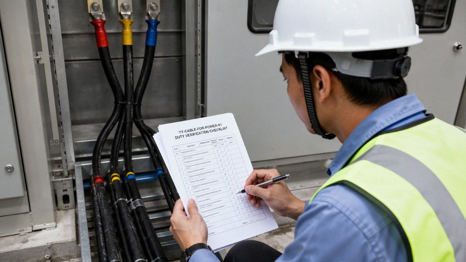
For project support, send Jinda the power duty, installation conditions, required standards, and procurement quantity, with clear route or panel photos if available. Jinda can review the application requirements, confirm suitable datasheets, discuss customized cable manufacturing options where appropriate, and plan bulk supply for international cable projects.