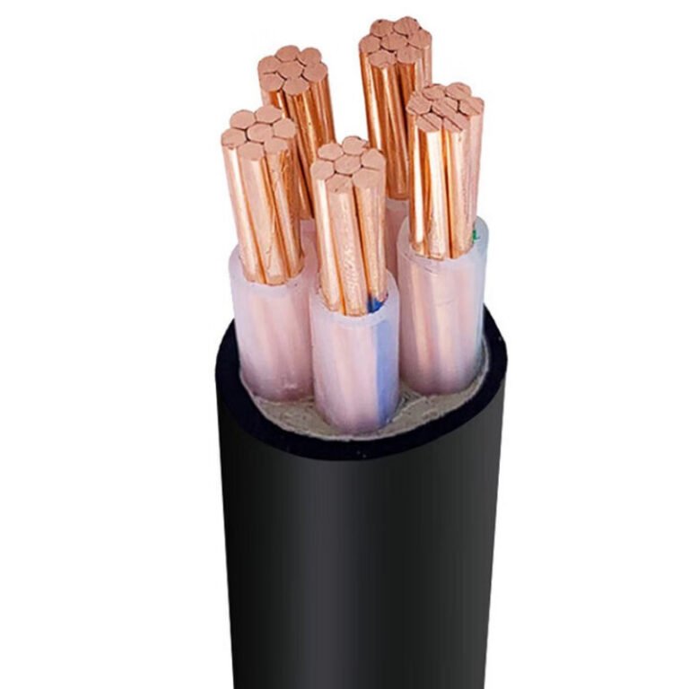
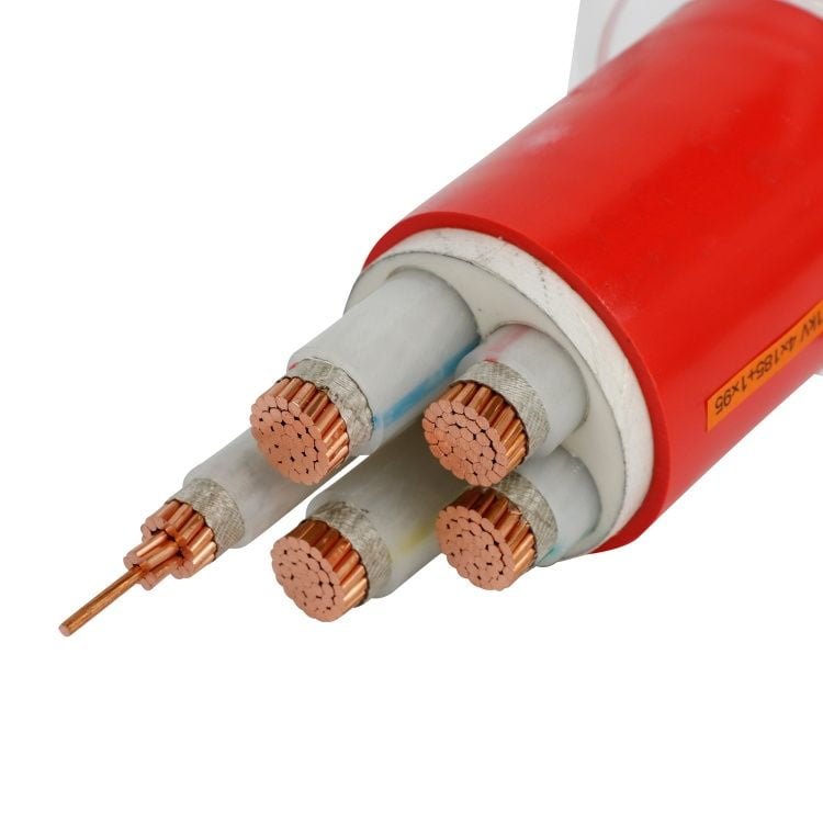
A cable run that looks harmless clipped along a wall can become the weak point in a plant, yard, or temporary production area. UV cracks the sheath, rain tracks into glands, forklifts clip exposed corners, and unsupported spans start to sag; then a cheap above-ground shortcut turns into nuisance trips, shutdown time, rework, and an awkward insurance or inspection conversation. The right answer is not “bury everything” — it is selecting, routing, supporting, protecting, and terminating the armoured cable for the exposure it will actually see.
Yes, armoured cable can often be left above ground, but only if the cable construction, sheath material, voltage rating, support method, impact protection, corrosion resistance, and terminations are suitable for the location and accepted by the applicable code or authority. Outdoor-rated armoured cable is not automatically approved for every exposed run.
The judgement sits in the details: SWA versus other armour types, PVC versus LSZH sheath, wall-mounted versus tray-supported routing, coastal corrosion, wet glands, vehicle zones, and whether the installation is under IEC, BS, NEC, CEC, or a local utility rule. This is where many specifications go vague, so the practical test is less “is it armoured?” and more “what can damage it between the panel and the load?”

Rules that decide legality
Legality is decided by the wiring rules adopted for the site, not by how tough the cable looks in your hand. A physically suitable armoured cable can still be rejected if its certification, declared wiring method, support arrangement, gland system, or environmental rating does not match the governing code and the authority having jurisdiction.
That distinction matters in procurement. A buyer may order a 0.6/1 kV armoured power cable built to a recognized construction standard and still have a problem at installation because the project specification requires a different listing, a local fire-performance class, sunlight-resistant marking, or a wiring method recognized by the local electrical code. The cable may be well made; the paperwork and installation method may still be wrong.
Manufacturer suitability is not the same as legal compliance
Manufacturer suitability answers questions such as:
- Is the cable designed for outdoor exposure?
- Is the sheath resistant to UV, moisture, oils, or chemicals expected on site?
- Is the armour corrosion-protected for the atmosphere?
- Is the voltage rating correct for the system?
- Can the cable tolerate the installation temperature and bending radius?
Legal compliance asks a different set of questions:
- Is this cable type recognized by the local electrical code for exposed installation?
- Is the standard printed on the cable accepted by the project jurisdiction?
- Is the cable listed or certified by the required certification body?
- Is the installation method permitted without conduit, tray, guard, or additional mechanical protection?
- Has the designer documented support spacing, bonding, glands, fire sealing, and inspection access?
That is where many above-ground cable arguments start. The maintenance team sees steel wire armour and assumes “mechanically protected.” The inspector sees an unsupported cable laid along a parapet, a gland without the right ingress rating, or a cable marking that does not show sunlight resistance, and rejects the installation. Both sides may be looking at the same cable, but they are judging different things.
Direct burial approval does not automatically mean a cable is approved for exposed above-ground installation.True
Direct burial suitability mainly addresses soil, moisture, and underground mechanical conditions. Exposed above-ground use introduces sunlight, impact, support, accessibility, fire routing, and termination requirements that must be accepted by the applicable code and cable certification.
The reverse mistake also happens. An indoor armoured cable approved for certain building wiring routes may not be acceptable outdoors on a wall or gantry if the sheath is not marked or documented for sunlight and wet locations. A black outer sheath is not proof of UV resistance. In practice, the submittal sheet, cable legend, test standard, and certification file matter more than the colour.
Who actually decides: codes, specifications, and the authority having jurisdiction
The final decision normally sits with the authority having jurisdiction, often called the AHJ in North American work. Depending on the project, that may be:
- A municipal or regional electrical inspector
- A utility engineer for service entrance or metering areas
- A mine safety authority
- A petrochemical or hazardous-area approval body
- A marine, rail, airport, tunnel, or infrastructure authority
- A project owner’s appointed electrical consultant
- An insurer or loss-control engineer
- A national standards enforcement agency
- A government client using its own specification
The national code is only the starting point. Large plants often add owner rules because they have lived with the failures: forklifts clipping wall-run cables, cable trays becoming storage shelves, sun-baked rooftop wiring cracking after a few summers, or armoured cables corroding where washdown water sits in saddle clamps. I have seen projects where the electrical code allowed a cable route in principle, but the owner’s engineering standard still required tray, guards, stainless cleats, or a minimum elevation above finished floor.
Utility rules can be even stricter near service equipment. Mining and petrochemical sites add another layer because damage consequences are higher and atmospheres may be classified. Insurers may focus on fire propagation, emergency egress routes, separation from fuel systems, and damage exposure. None of those groups cares that the cable is “heavy duty” unless the installation is documented in the language they accept.
Standards families are related, not interchangeable
IEC, British, North American, and local standards often deal with similar hazards, but they do not classify cable types in the same way. Treating them as interchangeable is a common procurement trap.
| Reference family | What it usually governs | Where mistakes happen |
|---|---|---|
| IEC practice, including IEC 60502 cable constructions and IEC 60364 installation principles | Cable design, voltage class, insulation systems, and general low-voltage installation rules in many IEC-based countries | Assuming an IEC cable construction is automatically accepted as a local exposed wiring method |
| British rules such as BS 7671, with cable standards such as BS 5467 and BS 6724 | Wiring design, protection, installation, and recognized cable constructions in UK-style projects | Confusing cable construction compliance with permission to install it anywhere exposed without protection |
| NEC in the United States | Defined wiring methods, listed cable types, use conditions, protection from physical damage, wet locations, sunlight, and hazardous areas | Supplying a cable that is robust but not listed as the required NEC cable type |
| CEC in Canada | Canadian wiring methods, certification, environmental use, mechanical protection, and installation rules | Assuming NEC acceptance or foreign certification will satisfy Canadian inspection |
| Country-specific adaptations | Local amendments, fire rules, utility practices, language, marking, and certification requirements | Using an export cable datasheet that omits the exact approval the local inspector expects |
A 0.6/1 kV armoured cable may be a normal low-voltage choice in many IEC or British Standard projects. That rating alone does not make it legal for a North American exposed installation, and it does not override a local rule requiring a particular listed cable type, raceway, tray, or protective guard. The mechanism is simple: codes define acceptable wiring methods, not just electrical strength. If the wiring method is not recognized, the inspector has no clean basis to approve it.
The trade-off for buyers is commercial as much as technical. Buying a globally available cable construction can reduce lead time and cost, especially for bulk industrial work. But if the project jurisdiction requires a local listing or a narrow product category, the cheaper cable can become expensive through redesign, replacement, inspection delay, and field labour. The “best” cable on paper flips to the wrong choice the moment the approval route is uncertain.
Markings and documents the inspector will look for
For above-ground armoured cable, the outer sheath marking and certification documents should be checked before purchase, not after drums arrive. At minimum, the engineering or procurement team should verify the required evidence for:
- Voltage rating, such as 0.6/1 kV where applicable to many low-voltage IEC or British Standard constructions
- Conductor material and size
- Number of cores or conductors
- Insulation type, for example XLPE or PVC where specified
- Bedding and sheath material
- Armour type, such as steel wire armour, steel tape armour, or aluminium wire armour depending on the cable design
- Applicable cable standard number
- Flame performance or low-smoke requirements where the route passes through buildings, tunnels, plant rooms, or escape routes
- UV or sunlight resistance for outdoor exposed runs
- Wet-location suitability where rain, washdown, condensation, or standing water can reach the cable
- Oil, chemical, or hydrocarbon resistance if the route crosses process areas
- Temperature rating, including ambient correction where cables run on roofs or near hot equipment
- Certification or listing mark required by the country or project
- Batch traceability and test certificates if demanded by the owner specification
Do not rely only on the sales description. Phrases like “outdoor cable,” “armoured,” or “weather resistant” are not precise enough for code approval. The usable evidence is the standard, listing, product datasheet, installation instructions, and cable marking. If those do not line up, a site inspector may reject a technically strong cable for reasons that are completely legitimate.
Locations where exposed above-ground runs often need extra protection
Even where above-ground armoured cable is allowed, exposed routing is commonly restricted in damage-prone or life-safety-sensitive areas. These are the places I would check first on a drawing review:
- Driveways and vehicle crossings: impact, crushing, and snagging risks usually push the design toward ducts, barriers, tray with guards, or rerouting.
- Forklift and pallet-truck zones: armour may resist some abuse, but repeated glancing hits can deform the sheath, loosen cleats, or damage glands.
- Public access areas: exposed cable invites tampering, climbing, vandalism, and accidental damage; codes and owners often require enclosure or guarding.
- Temporary construction areas: scaffold moves, welding leads, debris, and shifting traffic routes make “permanent-looking” exposed cable risky unless it is specifically installed as a compliant temporary system.
- Hazardous areas: glands, sealing, bonding, sheath materials, and cable type must match the area classification; ordinary outdoor suitability is not enough.
- Fire escape routes and protected corridors: flame spread, smoke, support survivability, and falling-cable risk may govern the installation.
- Sharp-edged steelwork: beam flanges, tray edges, roof sheet corners, and cable ladder cut ends can abrade the sheath unless radius protection and proper cleating are used.
- Rooftops and exposed pipe racks: sunlight, heat cycling, standing water, wind movement, and maintenance foot traffic can age the installation faster than expected.
- Washdown or coastal areas: corrosion of armour, cleats, glands, and support hardware can become the limiting factor rather than conductor ampacity.
Permanent installation normally means the cable is fixed, supported, relieved of strain, and terminated into equipment with compatible glands. Simply laying an armoured cable on soil, concrete, roofing membrane, or steelwork is rarely acceptable for a permanent industrial installation. It traps water, hides damage, creates trip hazards, and leaves termination points carrying mechanical load they were never meant to carry.
Support spacing should come from the applicable code, manufacturer guidance, cable diameter, route orientation, and environmental loading. A large multicore armoured cable on a vertical wall behaves differently from a smaller control cable clipped horizontally under a canopy. Wind, thermal movement, and vibration from nearby pumps or compressors can make a neat installation loosen over time if cleats are undersized or spaced by habit rather than calculation.
Bonding or earthing is another inspection point that gets missed. Metallic armour may need to be bonded correctly depending on the design, fault-protection method, and local rules. The gland is not just a mechanical accessory; it may be part of the electrical continuity, ingress protection, and strain-relief system. Wrong gland material, wrong seal, missing shroud, poor locknut engagement, or painted enclosure faces can all turn a compliant cable into a failed installation.
The practical boundary is this: if the cable is exposed to people, vehicles, weather, fire-critical routes, classified atmospheres, or public access, assume the installation method needs explicit approval rather than informal acceptance. The inspector is not judging only the cable drum; they are judging the whole installed wiring system, including documentation, supports, glands, route protection, markings, and access for future inspection.
Cable construction and exposure
Armour alone does not decide whether a cable will survive above ground; the armour, outer sheath, bedding, fillers, water-blocking, termination system, and current loading all work together. A steel wire armoured cable with the wrong sheath can fail faster outdoors than a lighter tray-rated cable that is actually UV-marked, wet-location rated, and installed with proper glands.
Common armoured cable families used above ground
Above-ground suitability starts with identifying the cable family, not just seeing “armoured” on a datasheet or purchase order. The same nominal voltage class, such as common 0.6/1 kV low-voltage power cable constructions under IEC or British Standard practice, can be built with very different exposure limits.
| Cable family | Typical strength above ground | Main exposure concern | Where I would be cautious |
|---|---|---|---|
| Steel wire armoured cable | Good impact and crush resistance; familiar for industrial feeders | Corrosion at damaged sheath, magnetic effects in some single-core AC arrangements, gland workmanship | Coastal sites, chemical areas, rooftop runs with poor support |
| Aluminium wire armoured cable | Non-magnetic armour option often used for single-core AC circuits | Lower mechanical strength than steel in some abuse conditions; accessory compatibility | Heavy traffic areas, places where cable may be struck or clamped badly |
| Steel tape armoured cable | Good radial protection against compression and some rodent damage | Less tolerant of bending, movement, and tensile pulling than wire armour | Exposed bends, vibrating steelwork, temporary-looking permanent installs |
| Metal-clad cable | Factory-applied metallic sheath or armour system with defined installation rules | Depends heavily on listing, bonding, environment rating, and connector system | Outdoor use unless the exact construction is marked and approved for it |
| Interlocked armour cable | Flexible metallic armour, quick to install in commercial and industrial work | Moisture path through armour unless jacketed and rated for wet/outdoor service | Washdown, rooftops, tray with standing water |
| Tray-rated armoured cable | Designed for cable tray routing when marked for the application | Mechanical protection may be lower than buried-style armour | Low-level exposed routes, forklift zones, ladder exits |
Steel wire armoured cable is often the instinctive choice because it feels robust in the hand and tolerates a rougher industrial environment. In plant work, that matters. A feeder running down a pipe rack column or across a service yard needs protection from tools, scaffold clips, pallet edges, and the occasional maintenance shortcut. The trade-off is that heavier armour raises cable weight, increases minimum bending radius, and makes glanding less forgiving.
Aluminium wire armour has a specific role that gets missed in rushed buying: single-core AC circuits. Ferromagnetic steel around a single conductor can suffer magnetic heating because the armour is exposed to alternating magnetic flux. Aluminium avoids that issue, which is why single-core AC armoured cables are often specified with non-magnetic armour or non-magnetic metallic layers. That advantage does not make aluminium the best answer everywhere; if the site has high impact exposure, the mechanical design and routing still need checking.
Steel tape armour is a different animal from steel wire. It resists radial compression well, but it is not as friendly where the cable must bend tightly, tolerate movement, or handle pulling loads. I have seen tape-armoured cable installed neatly in straight tray and perform well, then get abused at the last three metres into a motor terminal box because nobody allowed enough sweep, cleats, or gland space. The cable construction was not the only problem; the layout invited the defect.
Metal-clad and interlocked armour cables are common in North American-style installations and in equipment packages shipped internationally. They can be excellent when used within their listing and environmental markings. The mistake is assuming the metal covering is a weather seal. Often it is a mechanical and grounding system first, and the wet-location suitability depends on an overall jacket, connector rating, sealing method, and local code acceptance.
A cable is not automatically suitable for outdoor above-ground installation just because it has metal armour.True
Outdoor performance depends on the full cable construction, including outer jacket material, UV resistance, wet-location rating, corrosion protection, termination sealing, support method, and the applicable installation code or standard.
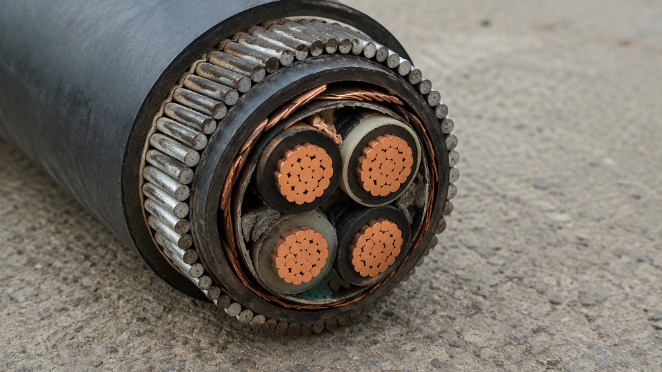
Armour material selection: strength, heating, and corrosion
Steel armour is selected mainly for mechanical strength. It gives good resistance to impact, crushing, and rough handling, especially in industrial yards, utility areas, and exposed building services. Galvanized steel improves corrosion resistance, but galvanizing is not magic. Once the outer sheath is cut, scraped, or cracked, water and contaminants can sit against the metallic layer, and corrosion starts where the protection is weakest: at damaged points, bends, cleat contact areas, tray contact lines, and gland entries.
Aluminium armour is selected when magnetic performance matters or when weight reduction helps installation. On long vertical rises, roof runs, or tray systems with limited load capacity, the weight saving is useful. The price paid is usually lower mechanical abuse tolerance compared with a heavy steel wire design, depending on the exact construction. That is why routing and guarding still matter. A cable that is electrically correct but mechanically exposed at ankle height beside a loading dock will not stay correct for long.
Specialty metallic layers are sometimes used where the hazard is not ordinary impact. Project specifications may call for lead sheath, copper wire screens, corrugated metallic sheaths, bronze components, or other barriers for chemical resistance, earth fault performance, rodent resistance, electromagnetic screening, or offshore service. Those are project-specific decisions, not catalog upgrades to add casually. They affect gland selection, bonding method, bending radius, delivery lead time, and scrap value risk on site.
The armour choice should match the hazard you actually have: mechanical abuse, magnetic heating, corrosion, electromagnetic requirements, or a combination of them. Over-specifying armour can create its own failures. A stiffer cable pulled around a tight tray corner may suffer sheath damage; a heavy cable without enough supports may sag between cleats; a difficult gland may be assembled badly by a tired crew using whatever brass fitting was left in the gang box.
The outer sheath is the first weather defence
Above ground, the outer sheath is usually more important for aging than buyers expect. Armour may take the hit, but the sheath decides whether sunlight, rainwater, oil mist, alkaline dust, or cleaning chemicals reach the layers below.
Common sheath choices include:
- PVC: Common for general industrial use, economical, and reasonably tough when correctly compounded. Outdoor PVC needs suitable UV stabilization; ordinary indoor-grade PVC can harden and crack under long sun exposure.
- LSZH compounds: Used where reduced smoke and halogen acid gas are required during fire. They are often specified in tunnels, enclosed galleries, public buildings, transport infrastructure, and substations. The outdoor and chemical behavior must be checked by compound grade, not assumed.
- PE: Strong moisture resistance and good outdoor durability in many applications. It can be less favorable where flame spread or smoke performance is the dominant requirement unless the specific compound is designed and tested for that duty.
- UV-resistant compounds: Needed for open tray, rooftop, façade, pole, and yard installations. The cable should be marked or documented for sunlight resistance according to the applicable standard or supplier data.
- Oil-resistant or chemical-resistant compounds: Useful near machine tools, hydraulic skids, fuel handling, wastewater, fertilizer, and process equipment. Resistance depends on the exact oil or chemical, temperature, concentration, and contact duration.
Sunlight damage is not just color fading, although fading is often the first visible warning. UV and heat can embrittle the jacket, reduce flexibility, open fine surface cracks, and allow water tracking along the sheath or into armour bedding. Once a crack starts on a dark sheath facing afternoon sun, seasonal movement can make it worse. A cable may look serviceable from the ground while the top side in the tray is already chalked, cracked, and wet underneath.
The boundary here is simple: if the manufacturer’s data, cable marking, or project specification does not confirm outdoor and UV suitability, do not treat above-ground exposure as harmless just because the cable is armoured.
Wet-location and water-ingress behavior
Rain is only the obvious water source. Condensation inside tray covers, rooftop ponding, washdown spray, sprinkler discharge, steam cleaning, and poor drainage can put a cable in wet service even when nobody calls the area “outdoors.” On roofs, a shallow tray can become a long gutter after a storm. In food plants and wastewater facilities, washdown water finds every low point and gland thread.
Water ingress usually follows one of several paths:
- Through damaged sheath: Cuts from pulling, sharp tray edges, burrs on Unistrut, or over-tightened cleats expose bedding or armour.
- Through poor terminations: Incorrect glands, missing shrouds, unsealed armour entry, wrong compression ring, or no drip loop lets water run into the cable end.
- By capillary movement: Stranded conductors, fillers, screens, and bedding can move moisture along the cable if the end is not sealed.
- Through accessories not rated for wet service: A cable may be suitable, while the connector, junction box, or gland is not.
- By standing water in tray: Constant immersion or repeated ponding is more severe than occasional rain splash.
This is where procurement language matters. “Outdoor cable” is not the same as “suitable for continuous immersion,” and “wet-location rated” does not automatically approve every termination arrangement. For critical feeders, especially outdoors or in tray exposed to process washdown, ask the supplier how the cable ends should be sealed during storage, pulling, and final termination. A surprising number of water problems begin before energization, with cable drums sitting open-ended in the yard for three rainy weeks.
Thermal exposure above ground
Above-ground cable often runs hotter than the nameplate current calculation suggests. Solar gain on a black sheath, hot steel structures, rooftop membranes, poor air movement, and grouping with other loaded circuits can all push conductor temperature upward. In a tray full of motor feeders, the center cables see a different thermal environment than a single cable clipped in free air.
The mechanism is straightforward: higher ambient temperature and reduced heat dissipation reduce the allowable current for the same conductor insulation temperature limit. Grouping makes it worse because neighboring cables reject heat into the same air space. A cable on a sun-heated roof or dark steel pipe bridge may have a local ambient far above the weather report. Current derating then becomes a design issue, not a paperwork exercise.
The trade-off is between mechanical protection and heat dissipation. Covered tray, conduit, or heavy guarding may protect against impact and sunlight, but it can trap heat or water if poorly detailed. Open tray cools better and drains better, but exposes the sheath to UV and physical damage. The preferred choice flips depending on whether the dominant risk is electrical loading, mechanical abuse, chemical exposure, or public contact.
Corrosive and dirty environments
Corrosion risk above ground is highly site-specific. Coastal salt spray attacks exposed metallic parts, especially at glands, cleats, tray supports, and damaged sheath. Fertilizer plants bring ammonia compounds and aggressive dusts. Chemical process areas may expose cable systems to acids, caustics, solvents, or intermittent vapor releases. Wastewater facilities combine moisture, hydrogen sulfide risk, biological contamination, and frequent washdown. Cement plants add alkaline dust, abrasion, vibration, and cleaning damage.
Galvanic corrosion deserves attention where dissimilar metals touch in the presence of moisture. Aluminium armour, steel tray, stainless hardware, copper earth links, brass glands, and galvanized supports can form corrosion cells if the detail is wrong. In practice, this often shows up at terminations and clamps rather than in the middle of a straight cable run. The cable datasheet may be correct, but the installed assembly becomes the weak point.
Useful checks before buying or approving construction include:
- Local atmosphere: marine, chemical, wastewater, fertilizer, cement, mining, or clean industrial air.
- Contact metals: armour, tray, cleats, glands, bonding straps, lugs, washers, and enclosure material.
- Drainage: whether water can sit at cable-to-metal contact points.
- Cleaning regime: pressure washing, alkaline foam, solvent wipe-down, or dry sweeping.
- Maintenance access: whether damaged sheath can be inspected without shutting down half the plant.
Flame, smoke, and enclosed-route requirements
Above-ground cable is often closer to people, equipment rooms, tunnels, cable galleries, and air-handling paths than buried cable. That changes the fire discussion. In substations, transport infrastructure, offshore modules, public buildings, enclosed industrial galleries, and tunnels, flame spread, smoke density, acid gas emission, and circuit integrity may matter as much as voltage rating or armour type.
PVC may be acceptable in many outdoor industrial routes, but it can produce dense smoke and halogen acid gases in a fire. LSZH designs reduce those emissions, which is why they are often specified for enclosed or occupied routes. The trade-off is that LSZH jackets are not all equally resistant to sunlight, oil, abrasion, or moisture. A good specification names the required fire behavior and the environmental exposure, rather than assuming one sheath material solves both.
Cable construction above ground is a system decision: armour for the abuse, sheath for the weather and chemicals, conductor and armour arrangement for electrical behavior, and accessories for sealing and bonding. The drawing may only show a line in tray, but the long-term performance is decided at the bends, supports, glands, roof penetrations, washdown zones, and sun-facing surfaces where the cable meets the plant.
Acceptable above-ground methods
Acceptable above-ground installation is not one method; it is a controlled route where the cable is supported, protected, identifiable, and inspectable for the whole service life. In practice, the best method is usually fixed mounting or tray/ladder work, with extra guarding at impact zones and carefully detailed transitions where the cable comes out of the ground or enters equipment.
Fixed surface mounting to walls, columns, brackets, and steelwork
Fixed surface mounting is common in plants because it gives a clear route and keeps the cable out of water, mud, forklift paths, and housekeeping damage. Armoured cable may be mounted to masonry walls, concrete columns, structural steel, Unistrut-type channel, fabricated brackets, or cable stanchions, provided the supports suit the cable diameter, weight, environment, and applicable wiring rules.
The details matter more than the word “armoured.” A poor saddle on a sharp angle bracket can damage an oversheath faster than weather exposure will. I like to see the installer check these items before pulling cable:
- Support spacing: Use the spacing required by the applicable code, cable manufacturer, and installation method. Larger multi-core armoured power cables need closer and stronger supports than light control cables, especially on vertical runs.
- Bend radius: Respect the cable’s minimum bending radius during installation and in its final position. The tight bend beside a motor isolator is a common place to find sheath stress and cracked glands later.
- Cleat compatibility: Cleats, saddles, or clamps should match the cable outside diameter and armour type without crushing the bedding or oversheath. For high fault-level circuits, cleats may need short-circuit withstand capability, not just mechanical support.
- Edge protection: Any contact with slotted channel, steel brackets, tray edges, or punched holes should be dressed, bushed, lined, or fitted with grommet/edge strip where needed.
- Thermal allowance: Do not strap cables tight across expansion joints, hot pipe racks, boiler-house steel, or sun-exposed metalwork without considering movement and derating.
Painted structural steel can look harmless in a new installation, but chipped paint, vibration, and rainwater can turn it into an abrasive support. Stainless or hot-dip galvanized hardware may be needed outdoors or in coastal and chemical areas, depending on the corrosion category and project specification.
Cable tray and ladder systems
Cable tray and ladder are usually the cleanest answer for long above-ground routes, especially in factories, utilities, water treatment plants, and process areas. They provide repeatable support, route visibility, and easier replacement than burying a failed cable under concrete. A tray route should be designed as an electrical support system, not treated as spare steelwork that happens to hold cable.
Key design checks include:
- Tray fill and grouping: Fill affects heat dissipation and future access. A tray that is packed flat on day one leaves no working room for inspection, clamp replacement, or additional circuits.
- Circuit separation: Power, instrumentation, data, fire alarm, and control circuits may need physical separation or separate containment to manage electromagnetic interference, fault risk, and code requirements.
- Drainage: Outdoor tray should not form troughs that hold water, drilling swarf, leaves, or coal dust. Ladder tray drains better than solid-bottom tray, but may need closer attention to small cable support.
- Cover selection: Covers protect against sun, falling objects, ice, or debris, but they can also trap heat and make inspection slower. In hot climates, a ventilated or raised cover may be better than a flat sealed cover.
- Bonding and earthing: Metallic tray or ladder systems may need bonding across joints and connection to the protective earthing system, depending on the wiring rules and whether the containment is relied on for protective continuity.
- Route accessibility: A tray above a crane runway, behind permanent ducting, or over a congested pipe bridge may be legal on a drawing but painful to maintain. Leave safe access for inspection, gland checking, and future pulling.
One trade-off is worth spelling out. Tray and ladder improve access and reduce random damage, but they also expose cable to ambient temperature, sunlight, and mechanical activity unless shields, covers, or barriers are used. The preferred option flips in a dirty washdown area, for example: an open ladder drains well, while a covered tray may collect residue unless it is sloped, ventilated, and routinely cleaned.
Clipped direct runs where allowed
Clipped direct runs can be acceptable for short, visible, low-risk routes, particularly along walls or dedicated service zones. They are less forgiving than tray because each cleat becomes part of the support design. Use cleats or saddles that hold the cable firmly without cutting into the oversheath, and keep the route straight enough that the cable is not forced to act like a spring between fixings.
Support is especially important at:
- Bends, where cable weight and stiffness load the first and last fixing.
- Terminations, where the gland and enclosure should not carry cable weight.
- Vertical drops, where the lower cleats must not slowly deform the sheath.
- Areas with vibration, such as beside compressors, crushers, pumps, fans, conveyors, and generator sets.
- Outdoor corners exposed to wind, where a loosely clipped cable can work against its own fixings.
A common maintenance shortcut is to replace one broken saddle with a random metal strap from the workshop. That may get the line running, but it can introduce galvanic corrosion, sharp bearing points, or inadequate fire performance. For export projects, specify the cleat type and material clearly enough that the buyer’s maintenance team can source like-for-like replacements five years later.
Conduit, trunking, and local guard protection
Conduit, trunking, channels, and guards are often used locally rather than for the entire armoured cable route. The aim is mechanical protection at vulnerable points, not cosmetic tidiness.
Use extra protection at:
- Exposed vertical drops from tray to machines or isolators.
- Road and walkway crossings.
- Entrances to buildings, substations, kiosks, and containerized equipment.
- Public or shared-access areas.
- Forklift routes, pallet staging zones, loading docks, and maintenance bays.
- Wall and floor penetrations.
- Places where cables pass near sharp concrete edges, steel decking, or removable panels.
Rigid steel conduit, heavy-duty PVC conduit, galvanized trunking, checker-plate guards, concrete cable covers, bollards, or fabricated steel shields may all be valid, depending on impact risk and environment. The guard should protect the cable without trapping water or making inspection impossible. If a guard has to be removed to inspect every gland or bend, maintenance crews will eventually stop removing it.
Where cable passes through walls or floors, sleeves should be sized so the cable is not jammed, and penetrations may need fire stopping, water sealing, vermin barriers, or gas sealing depending on the location. Any sealant or compound must be compatible with the cable sheath and the required fire or environmental rating.
Aerial and messenger-supported arrangements
Aerial armoured cable should only be used where the arrangement has been engineered for suspension loads. Armour improves mechanical resistance, but it is normally not a suspension system. Hanging a heavy low-voltage armoured cable from its own armour across a yard is a bad habit; the strain transfers into the sheath, armour bedding, glands, and terminations.
A proper aerial design considers:
- Cable weight and span length.
- Messenger wire or catenary strength.
- Sag at the hottest expected temperature.
- Tension at the coldest expected temperature.
- Wind loading and cable movement.
- UV resistance of the sheath and ties.
- Strain relief at each end.
- Clearances over roads, walkways, vehicles, stored material, and equipment.
- Corrosion of messenger hardware and clamps.
- Earthing or bonding requirements for metallic supports.
This method has a narrow operating window. It can work well for temporary site power or engineered crossings where trenching is not possible, but it should not be improvised by pulling cable tight between two buildings and hoping the glands hold.
Temporary above-ground installations
Temporary does not mean casual. Construction power, event supply, dewatering pumps, mining support, outage bypasses, and emergency generator feeds often use above-ground armoured cable because the route must move or disappear later. The controls are different from a permanent tray route: duration, inspection frequency, and physical segregation carry more weight.
A workable temporary setup normally includes:
- A defined route on a marked drawing or site sketch.
- Barriers, ramps, mats, cable protectors, or raised supports at crossings.
- Separation from excavators, telehandlers, welding areas, sharp scrap, and standing water.
- Regular inspection after storms, vehicle movement, blasting, crane lifts, or shift changes.
- Clear ownership: someone must know who is allowed to move the cable.
- Correct terminations and weatherproof connectors, not taped joints sitting in mud.
The boundary is simple: once a “temporary” route becomes part of normal production, it should be reviewed as a permanent installation. Plants are full of temporary cables that survived the first shutdown and then stayed for six years. That is where risk quietly accumulates.
Armour alone does not make a cable suitable to be laid loose on open ground as a permanent installation.True
Armour provides mechanical resistance, but permanent above-ground routing still needs support, route control, environmental suitability, termination sealing, protection from abrasion and impact, and compliance with the applicable electrical rules.
Why loose open-ground laying is usually poor practice
Simply laying armoured cable across open ground is usually the weakest permanent method. It looks cheap during installation because there is no tray, trench, bracket, or guard to buy. The cost tends to reappear as damaged sheath, nuisance outages, unsafe access, and arguments about who drove over the cable.
The main failure drivers are predictable:
- Abrasion against stone, concrete, ballast, steel grating, or compacted soil.
- Water pooling around damaged oversheath, glands, or low spots.
- Crushing by vehicles, pallets, skips, jacks, or temporary equipment.
- Trip hazards and poor housekeeping.
- Vegetation growth that hides the route and holds moisture.
- Rodent damage, especially where cable sits in warm sheltered edges.
- No reliable route control during future excavation, cleaning, or plant modification.
- Difficulty inspecting the underside of the cable.
There are limited situations where a cable may be placed at grade for short duration with protection and inspection, but that is a controlled temporary installation, not a respectable permanent design.
Transitions between underground and above-ground sections
The change from buried to exposed cable deserves more attention than it usually gets. This is where moisture, corrosion, UV, mechanical impact, and poor bending practice all meet in one small area.
Good transition detailing normally includes:
- A riser guard or heavy conduit from below grade to a safe height.
- Smooth entry and exit points with no sharp sleeve edges.
- Drainage so water does not run down the cable into the duct or enclosure.
- Sealing against water, soil, insects, and rodents where required.
- Corrosion-resistant glands, cleats, bands, and fixings.
- Oversheath protection where the cable exits concrete, asphalt, or steel plate.
- Identification tags showing circuit, source, destination, voltage, and route reference.
- Space to re-terminate the cable without dismantling half the support system.
For steel wire armoured cable, gland selection and installation quality are critical at these points. A weatherproof gland installed without the correct shroud, washer, thread engagement, or earthing continuity can turn a mechanically sound route into a reliability problem. Always verify the actual gland system against the cable construction, enclosure rating, and local earthing practice.
Inspection and maintenance access
Inspection access should be designed into the route before procurement, especially on long industrial cable runs and international projects where the maintenance crew may not know the original design intent. Cable schedules, route markers, tray labels, and termination tags are not paperwork decoration; they are what let the next technician isolate the right feeder at 2 a.m. without tracing a black cable through three buildings.
For maintainable above-ground routes, specify:
- Safe walking or platform access to inspect trays, glands, cleats, and guards.
- Enough clearance to open covers and remove cable clamps.
- Labels that survive UV, washdown, oil mist, and heat.
- Spare tray space or planned expansion zones where future loads are likely.
- Inspection intervals tied to exposure: public impact zones and temporary routes need more frequent checks than indoor wall-mounted feeders.
- Documentation of any engineered aerial spans, special cleats, fire barriers, or separation requirements.
Above-ground armoured cable can be a good engineering choice when the route is visible, supported, protected, and maintainable. The method stops being acceptable when the cable is merely “tough enough” in someone’s opinion but lacks controlled support, impact protection, environmental suitability, and a way for future crews to inspect and identify it.
Failure risks above ground
Above ground, armoured cable usually fails from the outside inward before it fails electrically: impact, abrasion, sunlight, water, corrosion, heat, and poor bonding do the damage first. The armour buys mechanical resistance, not immunity, and it does not remove the need for routing control, support design, gland selection, earthing verification, and inspection access.
The most common mistake I see is treating “armoured” as if it means “can be left anywhere.” It cannot. A cable clipped along a quiet wall at shoulder height lives a very different life from one lying across a loading bay, strapped to a vibrating pump skid, or crossing a roof where workers drag scaffold boards and HVAC panels.
Mechanical impact and crushing
Vehicle and maintenance damage is the obvious above-ground risk, but it is often underestimated because the cable looks rugged. Forklift tyres, pallet truck wheels, mobile access platforms, crane outriggers, rolling gates, hinged steel doors, temporary scaffolding, dropped spanners, and dragged machinery bases can all deform the cable enough to damage the bedding, insulation, or cores without fully cutting the oversheath.
Typical high-risk locations include:
- Door thresholds and roller-shutter openings.
- Loading docks and warehouse aisles.
- Plant-room floors where pumps, valves, and filters are serviced.
- Temporary construction routes.
- Cable drops below about knee height unless guarded.
- Areas behind swing gates, sliding gates, or removable machine guards.
- Roof walkways where contractors carry tools, cylinders, or metal framing.
The mechanism is simple: the armour spreads some impact load, but point loading still ovalizes the cable. Once the circular geometry is disturbed, conductor insulation can be pinched, armour wires can bite inward, and sheath cracks may form at the crush line. A megger test immediately after damage may still pass; the failure often appears months later after moisture and thermal cycling have done their work.
The trade-off is access versus protection. An exposed route is easy to inspect and modify, but every accessible metre also becomes vulnerable to the next mechanic with a ladder, pry bar, or pallet jack. In traffic areas, the better answer is usually relocation, rigid containment, bollards, raised support, or a purpose-designed cable guard rather than simply choosing a heavier armoured cable.
Abrasion, movement, and support damage
Abrasion is quieter than impact and just as destructive. Cables rubbing on concrete, roof ballast, tray edges, unbushed holes, threaded rod, sharp Unistrut ends, corroded brackets, or vibrating machinery can lose oversheath thickness long before anyone notices. Thermal expansion adds a slow sawing action: a long black cable in sun may move a few millimetres each day against the same high spot.
Watch for these installation details:
- Tray edges without radius protection.
- Cable ties pulled too tight, especially nylon ties outdoors.
- Metal banding used directly over the sheath.
- Cleats with the wrong internal profile or over-tightened bolts.
- Long unsupported spans that let the cable sway.
- Cable resting directly on rough concrete or roof chippings.
- Vibration transfer from motors, compressors, fans, and packaged skids.
If the sheath can move against a hard edge, the design should assume it will eventually wear there. Good supports hold the cable without crushing it, allow controlled expansion, and avoid knife-edge contact. In practice, a cheap rubber liner or proper saddle can prevent a repair that later requires shutdown permits, isolation, re-glanding, and retesting.

UV degradation and weather cracking
Outdoor exposure is not just “wet or dry.” Sunlight ages many polymer oversheaths, especially if the material is not rated for long-term UV exposure. The surface can chalk, harden, shrink, or crack. Once cracking starts, bending at supports and glands opens the path for water ingress.
This risk changes by climate and route. A shaded north-facing wall may be forgiving. A roof in a hot, dusty, high-UV region is not. Dark sheaths absorb solar heat, so the same sunlight that degrades the polymer also raises conductor temperature and reduces current-carrying margin. If the cable construction or supplier documentation does not confirm sunlight resistance for the installed environment, the design assumption should be conservative.
Water ingress, wicking, and termination failures
Water usually enters above-ground cable systems through details, not through the middle of a perfect sheath. Damaged oversheath, poorly matched glands, unsealed cable ends, downward-facing but unsealed terminations, junction boxes with failed gaskets, and low points that collect water are all common paths.
The trouble is that water does not always stay where it entered. Depending on the cable construction, bedding materials, conductor stranding, and temperature cycling, moisture can migrate along the cable. Condensation inside outdoor junction boxes is another nuisance; a box can be “weatherproof” against rain and still breathe moist air in and out daily. After a cold night, droplets form on terminals, gland plates, and armour interfaces.
Good practice includes:
- Correct outdoor-rated glands for the cable type and armour form.
- Proper shrouds, seals, washers, and thread sealing where required by the gland system.
- Sealing spare or cut cable ends immediately, not “after lunch.”
- Avoiding low points where water sits around the sheath or gland.
- Drainage or breather strategy for enclosures where condensation is expected.
- Inspection after the first wet season, not only at commissioning.
Corrosion of armour, glands, supports, and bonding hardware
Corrosion is a system problem. The cable armour may be galvanized steel, the gland may be brass or nickel-plated brass, the tray may be galvanized steel, the fixings may be stainless, and the local atmosphere may contain salt, fertilizer dust, acid fumes, caustic washdown, or fine metal particles. Put those together carelessly and the weakest interface becomes the maintenance item.
Risk rises sharply in:
- Coastal sites and offshore-adjacent facilities.
- Chemical plants, wastewater areas, fertilizer stores, and battery rooms.
- Food plants with regular washdown and cleaning chemicals.
- Cable routes touching wet soil, damp concrete, or roof debris.
- Mixed-metal assemblies without compatible washers or isolation.
- Locations where water sits inside tray or under cleats.
Corrosion matters electrically as well as mechanically. Armour continuity, gland grip, earth tags, banjos, locknuts, and bonding jumpers can all degrade. A cable may still carry load normally while its fault path has become unreliable, which is exactly the kind of hidden defect that hurts people during a fault.
Electrical overheating and derating errors
Above-ground routes can run hotter than the designer expected. Grouped cables on tray, direct sun, dark sheath color, poor air movement, harmonics, undersized conductors, and high ambient temperature all reduce current-carrying capacity. Loose terminations and gland assemblies add local heating; I have seen more nuisance heat at terminations than in the middle of a properly sized run.
The engineering path is not mysterious. Current produces I²R loss in the conductor. If the cable cannot reject that heat because it is bunched, sun-heated, covered in dust, or installed near hot pipework, conductor temperature rises. Higher conductor temperature increases resistance, which creates still more heat. Insulation life then shortens, and terminals lose spring pressure or loosen under thermal cycling.
The preferred choice can flip depending on the route. Open tray improves cooling and inspection, but it exposes the cable to sunlight, mechanical damage, and unauthorized contact. Conduit or covered containment gives protection, but can worsen heat dissipation and make water trapping harder to see. Final ampacity needs the actual installation method, grouping, ambient temperature, load profile, harmonic content, and applicable standard tables or software, not a catalogue current rating copied into a procurement sheet.
Fault current, bonding, and armour continuity
Armour should not be assumed to be an adequate protective conductor unless the design proves it. That means checking fault current capacity, earth fault loop impedance or equivalent disconnection criteria, gland compatibility, continuity across joints, and the bonding arrangement required by the applicable standard and authority.
Steel wire armour can always be used as the sole protective conductor for an above-ground power cable.False
Armour may be permitted as a protective conductor in some designs, but only after fault current capacity, continuity, disconnection performance, gland systems, and local code requirements are verified. Some installations require a separate protective conductor or supplementary bonding.
This is one place where procurement shortcuts cause site arguments. A buyer may order “SWA cable” correctly by voltage and core size, but miss the required glands, earth tags, shrouds, bonding jumpers, cleats, or test requirements. The cable then arrives on site, the installer improvises, and the as-built fault path is not what the design engineer intended.
Single-core AC cable hazards
Single-core AC armoured cables need special care above ground. If single-core cables use ferrous armour or pass through ferrous gland plates, ferrous enclosures, or steel clamps incorrectly, magnetic effects can cause induced currents and heating. Formation also matters: trefoil, flat spacing, transposition, bonding method, and phase balance all influence impedance, sheath or armour losses, and forces under fault conditions.
Do not treat three single-core cables like a three-core cable split into pieces. The installation hardware must be compatible with single-core AC service, including non-ferrous glands or plates where required, suitable cleats for short-circuit forces, and a bonding arrangement verified by calculation or manufacturer guidance.
Fire, smoke, and occupied-area exposure
Above-ground routes often pass through places people occupy or depend on during an emergency: corridors, risers, plant rooms, control rooms, escape routes, tunnels, and critical production areas. In those zones, flame spread, smoke density, acid gas emission, circuit integrity, and fire stopping can matter as much as basic electrical insulation.
The correct cable choice may need flame-retardant, low-smoke zero-halogen, fire-resistant, or circuit-integrity construction, depending on the route and function. A standard armoured power cable that is acceptable outdoors on a boundary wall may be a poor choice through a control room ceiling void. The boundary of any simple “armoured is suitable above ground” conclusion stops as soon as the route enters an area with life-safety, evacuation, smoke-control, or critical-service requirements.
Human-factor failures
People create a large share of above-ground cable damage. They step over low cables until someone trips. They hang temporary lights from them. They move a cable to fit a new pipe bracket and forget to update the drawing. They assume a dead-looking armoured cable is abandoned. A contractor cuts a route because the identification tag fell off three winters ago.
Control measures are basic but not optional:
- Permanent cable identification at sensible intervals and at terminations.
- Route drawings updated after changes, not only after major projects.
- Physical guarding where people can stand, drive, or store material.
- Lockout and proving-dead procedures before maintenance.
- Segregation from temporary services and construction traffic.
- Clear ownership for inspection after storms, shutdowns, and contractor work.
Above-ground armoured cable can be reliable, but only when it is treated as an engineered exposed system rather than a tough-looking product. The weak point is rarely the cable catalogue description; it is the route detail, the gland, the support, the derating assumption, or the undocumented change made during the next maintenance job.
Specification and purchasing checks
Use the RFQ to describe the service condition, not just the cable size. For above-ground armoured cable, the buying risk is usually not that the copper or aluminium is completely wrong; it is that the sheath, armour, documentation, accessories, or logistics package is under-specified and the site team discovers the gap after the drums arrive.

Define the installation environment before asking for a price
A cable quoted for “outdoor use” can still be a poor fit if the supplier does not know what outdoor means on that site. A shaded plant room wall, a rooftop cable tray in direct sun, and a coastal pipe rack with salt spray are three different purchasing specifications.
At RFQ stage, state the following conditions clearly:
- Indoor or outdoor route: Include whether the cable is fully exposed, partly under cover, inside a ventilated tunnel, on tray, clipped to wall, or routed through short sections of conduit.
- Sunlight exposure: Direct UV on a roof or yard rack needs a sheath compound and cable marking suitable for sunlight exposure. Black sheath is common for UV performance, but do not assume color alone proves UV suitability.
- Rain and standing water: Above-ground does not always mean dry. Cable on sagging tray, in unsealed conduit, or behind a parapet can sit in water after storms.
- Chemical exposure: Identify oils, fuels, solvents, acids, alkalis, fertilizers, washdown chemicals, and airborne process vapors. This is where a standard PVC oversheath may be cheap and wrong.
- Ambient temperature range: Give both normal and extreme values. Rooftop cable in summer sun can run much hotter than the weather report suggests.
- Elevation and routing height: A cable at ground-level along a fence line faces different impact, vandalism, and water risks than one on a 6 m pipe rack.
- Coastal or corrosive conditions: Salt-laden air changes the discussion around armour corrosion, gland material, support hardware, and exposed metallic parts.
- Mechanical impact level: Forklift traffic, scaffold work, maintenance trolleys, livestock, hand tools, and dropped components all matter. “Armoured” is not a license to leave cable in a damage zone without guards.
- Expected service life: A temporary feed for a six-month construction compound is not purchased the same way as a 25-year utility or industrial installation.
The mechanism is simple: the oversheath and metallic armour are the first defence against weather and handling, while insulation is the last defence for electrical integrity. If the outer jacket cracks from UV or chemical attack, water tracks toward glands and bedding, armour corrosion accelerates, and a cable that passed factory tests can become a maintenance nuisance long before its electrical design life is reached.
Specify the electrical requirements without leaving design gaps
Procurement should not be forced to guess the electrical design. Give enough information for the supplier and design engineer to check whether the requested cable construction is sensible.
Include at least:
- System voltage: For many IEC and British Standard low-voltage armoured power cable constructions, 0.6/1 kV is common, but the project standard must govern.
- AC or DC service: DC systems can change insulation stress, polarity identification, protective device selection, and termination practice.
- Conductor material: Copper or aluminium, including any project preference for compacted, stranded, or flexible conductors where applicable.
- Conductor size: State the required cross-sectional area and whether the size is based on load current, voltage drop, fault withstand, or a client standard.
- Number of cores: Include phase cores, neutral, and any separate protective conductor requirement.
- Earthing arrangement: Do not assume the armour is automatically acceptable as the protective conductor. That depends on local rules, fault level, armour type, termination quality, and design calculation.
- Prospective fault level and clearing time: Needed for short-circuit rating and protective conductor assessment.
- Load current and duty profile: Continuous load, cyclic load, motor starting, transformer inrush, EV charging, crane duty, or standby generator use all affect thermal assumptions.
- Voltage drop limit: Especially important on long outdoor runs to pumps, lighting, gatehouses, compressors, and remote skids.
- Harmonic content: Nonlinear loads may require neutral sizing checks and derating, particularly in multi-core low-voltage distribution.
A common buying mistake is ordering cable by ampacity table only. Current-carrying capacity is not a universal number; it depends on installation method, grouping, ambient temperature, conductor operating temperature, tray ventilation, solar gain, and local code calculation method.
Specify the cable construction, not just “SWA cable”
“Armoured cable” covers a wide range of constructions. The RFQ should name the required standard where applicable, such as IEC 60502, BS 5467, BS 6724, or another project-specified construction, then define any extras needed for the exposure.
Use a construction checklist like this:
| Requirement | What to specify | Why it matters above ground |
|---|---|---|
| Insulation | XLPE, PVC, EPR, or project-specified material | Controls operating temperature, dielectric performance, and overload tolerance |
| Bedding | Compatible bedding under armour | Poor compatibility can lead to deformation or moisture paths |
| Armour type | Steel wire, steel tape, aluminium wire, or other specified armour | Affects impact resistance, flexibility, corrosion behavior, magnetic losses, and earthing design |
| Oversheath compound | PVC, PE, LSZH, oil-resistant, UV-resistant, or special compound | Main defence against sunlight, water, chemicals, abrasion, and smoke requirements |
| Sheath color | Usually project-defined; black often requested outdoors | Color helps identification but does not replace compound certification |
| Flame performance | Standard flame-retardant or higher project requirement | Relevant where cable runs near buildings, escape routes, or process areas |
| Low-smoke requirement | LSZH where specified by code or client | Often required in tunnels, stations, public buildings, and enclosed industrial areas |
| Oil or chemical resistance | State the fluid type and exposure pattern | Splash exposure and immersion are not the same duty |
| Termite or rodent resistance | Required in certain regions or site conditions | Armour helps, but sheath and installation protection still matter |
| Water-blocking | Conductor or screen water-blocking if needed | Useful where water migration along the cable could create wide repair zones |
The trade-off sits mainly between durability, handling, and cost. A tougher PE or special compound sheath may resist abrasion and moisture better than general PVC in some outdoor duties, but it may have different flame behavior, gland sealing behavior, marking performance, or code acceptance. LSZH may satisfy smoke and halogen limits, yet not automatically give the best oil or UV resistance. The preferred choice flips when the route changes from open outdoor tray to enclosed public-access space, or from clean utility yard to oily process plant.
Request evidence rather than accepting assumptions
A cable that is “made to standard” should be backed by documents that match the ordered product, voltage rating, construction, and batch. Ask for documentation before shipment, not after a commissioning engineer is standing beside an open drum with a phone in one hand.
For international projects, request:
- Applicable standard and cable designation
- Type test reports for the relevant cable family and construction
- Routine test records for the manufactured batch where applicable
- Factory test certificate
- Declaration of conformity
- Third-party approval or certification where the project, authority, or client specification requires it
- Traceable cable markings showing manufacturer, voltage rating, size, core count, standard, year or batch identification, and other required marks
- English-language documents and markings if the project team, inspector, or end user requires English records
The cheapest compliant-looking cable can become the most expensive option if it lacks the correct sheath rating, test documents, approvals, or termination compatibility for above-ground service.True
Procurement cost is only one part of installed cost. Missing documentation can delay energization, unsuitable sheath compounds can shorten service life, and incompatible glands or lugs can force rework during installation. The exact financial impact depends on project schedule, inspection regime, and replacement access.
Include accessories in the same purchasing review
Many above-ground cable problems begin at the accessory interface. The cable itself may be acceptable, while the gland is the wrong material, the shroud traps water, the earth tag is forgotten, or the lug barrel does not suit the conductor class.
Check compatibility for:
- Cable glands: Armour type, sheath diameter, ingress protection, material, hazardous area approval if required, and corrosion suitability.
- Shrouds and seals: UV and weather suitability; avoid designs that hold water against the gland.
- Earth tags, locknuts, and bonding conductors: Matched to fault current duty and local earthing practice.
- Cable cleats and clamps: Correct for cable outside diameter, route spacing, short-circuit forces, UV exposure, and support material.
- Cable lugs: Copper or aluminium conductor compatibility, palm hole size, barrel length, crimp die system, and plating.
- Heat-shrink or cold-shrink parts: Outdoor rating, voltage class, adhesive sealing, and compatibility with sheath compound.
- Termination kits: Especially for screened, medium-voltage, or special constructions; do not improvise kits across cable families.
- Cable tray hardware and protective guards: Stainless, hot-dip galvanized, coated, or non-metallic support choices should match the environment.
- Identification tags: Outdoor-readable, mechanically secure, and consistent with the project tagging system.
In practice, I prefer accessory schedules to reference actual measured cable diameter tolerances from the supplier datasheet. Nominal diameter is useful for budgeting, but gland selection gets awkward when the delivered cable sits near the top or bottom of the tolerance band.
Ask for installation data before the drums ship
Installation data should be part of the submittal package. It prevents field crews from treating heavy armoured cable like building wire.
Request:
- Minimum bending radius: During pulling and after installation; the two values may differ.
- Maximum pulling tension: Include whether the limit applies to conductor pulling, pulling eye, stocking grip, or armour.
- Maximum sidewall pressure: Relevant for bends, rollers, and tray transitions on long pulls.
- Maximum operating temperature: Based on insulation and installation assumptions.
- Short-circuit rating: Conductor and, where relevant, armour or protective conductor duty.
- Current-carrying capacity and derating guidance: For tray, conduit, wall mounting, grouping, ambient temperature, and solar exposure where supported.
- Cable weight: Needed for tray loading, support design, manual handling, and lifting plans.
- Overall diameter and tolerance: Needed for glands, cleats, trays, and penetrations.
- Drum dimensions and gross weight: Check container loading, site forklifts, drum jacks, and storage space.
- Storage instructions: End caps, drum orientation, sunlight exposure, temperature, and moisture protection.
If the supplier cannot provide the data needed to install the cable correctly, the unit price is not a complete commercial offer. That does not mean every small project needs a thick dossier, but above-ground cable on an industrial or infrastructure site needs enough information for design, inspection, and maintenance records.
Plan bulk procurement and export logistics
Bulk cable buying is where small specification gaps multiply. A wrong drum length on one feeder can leave a joint in a poor outdoor location; a missing project tag can send the right cable to the wrong area; poor end sealing can allow moisture into a cable that waits three months in a yard before installation.
For larger orders, define:
- Drum length and cutting tolerance: State whether lengths are exact, minimum, or plus/minus tolerance. Include spare length for terminations and routing changes.
- Drum schedule by circuit: Match drum number to cable tag, route, size, length, and destination area.
- Packaging for sea freight: Export drums, lagging, wrapping, lifting points, and protection against handling damage.
- Moisture protection: Sealed ends, caps, and inspection on arrival.
- English markings: Cable sheath marking, drum labels, packing lists, test certificates, and project documents.
- Project tags: Circuit numbers, purchase order references, destination, and installation area.
- Inspection hold points: Pre-production document review, in-process checks if required, final inspection, witness testing if commercially justified, and release documentation.
- After-sales support: A clear contact path for document corrections, installation questions, batch traceability, or nonconformance handling.
This is where supplier structure matters. Jinda’s manufacturing profile is relevant to project buyers because the company has multiple production bases, integrated R&D and production, export experience across more than 50 countries, technical support, and after-sales service. For a buyer managing repeat orders or phased projects, that can help coordinate specification control, documentation packages, and long-term supply consistency across more than one shipment.
The boundary is still the project standard and local authority requirement. A manufacturer can support cable selection and documentation, but the final purchasing specification must be checked against the current design code, client standard, installation method, and approval regime for the site where the cable will actually be installed.
Inspection before energizing
Use a disciplined walkdown sequence, not a casual “looks good” check from the switchroom door. I like to inspect from source to load with the approved drawing set in hand, then repeat the route in the opposite direction after terminations are open, because missed cable IDs and poor gland work are easier to catch from different angles.
- Verify the cable identity against drawings and purchase documents
- Match the installed cable to the approved cable schedule:
- Cable type and construction
- Circuit number
- Route number or tray reference
- Voltage rating, such as 0.6/1 kV where specified
- Conductor size
- Core count
- Armour type
- Outer sheath material and color, if specified
- Standard reference, such as IEC 60502, BS 5467, BS 6724, or the project-specific requirement
- Read the sheath marking at several points, not only near the drum end. Paint, dust, and sun glare can hide a wrong drum surprisingly well.
- Check drum numbers, delivery notes, inspection release documents, and any factory test certificates required by the project.
- Confirm that any cable substitutions were formally approved. A cable that is electrically similar may still be wrong for UV exposure, flame performance, low-smoke requirements, gland compatibility, or local authority acceptance.
- Match the installed cable to the approved cable schedule:
- Inspect the above-ground route for physical exposure
- Walk the full route slowly and look for conditions that will attack the cable over time:
- Forklift lanes, crane access, vehicle crossings, and pallet drop zones
- Sharp tray edges, unprotected steelwork, cable ladder burrs, and unfinished bracket cuts
- Hot pipework, exhaust ducts, steam tracing, heaters, and sun-heated metal surfaces
- Moving guards, conveyor frames, pump skids, vibration points, and removable machine panels
- Standing water, roof drainage paths, washdown areas, and low points on outdoor racks
- Chemical splash from dosing skids, battery rooms, plating lines, process vents, or cleaning stations
- Areas accessible to unauthorized personnel
- Future maintenance conflicts, such as valve pull space, motor removal paths, filter access, or scaffold routes
- Do not accept “it has armour” as the protection argument. Armour improves mechanical resistance, but it does not make a cable immune to repeated rubbing, crushing, chemical attack, heat ageing, or bad routing.
- Walk the full route slowly and look for conditions that will attack the cable over time:
- Check supports, cleats, tray, and restraints
- Confirm cleat or support spacing against the project design, cable manufacturer’s data, and applicable installation rules. Long unsupported spans lead to sagging, sheath creep, and extra load at glands.
- Check cable tray and ladder condition:
- No missing covers where covers are specified
- No collapsed rungs
- No standing water inside enclosed tray
- No loose tray joints
- No sharp galvanizing spikes or cut edges touching the sheath
- Verify minimum bend radius at corners, offsets, risers, and terminations. The worst bends are often behind panels where installers had little room and wanted the door to close.
- Look closely at clamps and cleats. Overtightening can flatten the sheath, create pressure marks over the armour, and start a water path along the bedding. The trade-off is real: loose restraints allow movement under vibration or fault forces, but excessive compression damages the cable before it is ever energized.
- Confirm vertical support and strain relief. A vertical drop into a gland should not leave the gland carrying the cable weight.
- Allow for thermal expansion on outdoor racks and long straight runs. A cable tied hard at every bracket may look tidy in winter and buckle or pull at terminations in summer.
- Inspect terminations, glands, and enclosure entries
- Confirm the gland type matches the cable armour, sheath, enclosure, and environment. Indoor brass glands in a wet outdoor location are a classic commissioning defect.
- Check:
- Armour wires or tape are correctly prepared and clamped
- Bedding and outer sheath are not cut too far back
- Seals are fitted, compressed, and installed in the right order
- Shrouds are present where specified
- Earth tags, serrated washers, locknuts, and banjo washers are fitted correctly
- Enclosure ingress rating is maintained after drilling and gland installation
- Corrosion compatibility is acceptable for the atmosphere, enclosure material, and gland material
- Conductor lugs are the right barrel size, correctly crimped with the specified die, and not strained at the terminal
- Tugging a conductor by hand is not a substitute for a proper crimp inspection, but it will catch some embarrassing failures before they become hot joints.
- Confirm bonding and earthing
- Verify armour continuity across every joint, gland, junction box, and equipment connection.
- Confirm protective conductor sizing against the project design and applicable rules. Do not assume the armour alone is an adequate protective conductor unless that was calculated and accepted.
- Check the earth fault loop path and protection philosophy:
- Armour used as CPC
- Separate CPC installed with the cable
- Tray or ladder included as a bonded metalwork system
- Local supplementary bonding
- RCD, fuse, or circuit-breaker disconnection assumptions
- For single-core armoured cables, confirm the bonding arrangement before energizing. Single-point bonding, both-end bonding, cross-bonding, and non-magnetic armour choices have different loss, heating, and fault-current behavior. A wrong bonding decision can create circulating currents and heating that will not be obvious during a quick no-load test.
- Check tray bonding jumpers at expansion joints, removable sections, painted interfaces, and bolted joints. Paint under a lug is not an earth connection.
- Perform electrical and commissioning tests
- Select tests according to the governing standard, equipment connected, voltage class, and project commissioning procedure. Common checks include:
- Conductor continuity
- Protective conductor and armour continuity
- Insulation resistance
- Polarity
- Phase identification and phase rotation
- Earth fault loop impedance or equivalent verification
- Sheath integrity testing where applicable and permitted
- Functional checks of protective devices and interlocks
- Disconnect sensitive equipment before applying insulation test voltages if required by the manufacturer. Drives, surge protection devices, soft starters, meters, and control electronics are easy to damage with an otherwise normal test.
- An insulation resistance result proves condition at the time of test; it does not prove that the route is mechanically safe or correctly protected for years of above-ground service.
- Select tests according to the governing standard, equipment connected, voltage class, and project commissioning procedure. Common checks include:
A pre-energizing inspection is both a safety control and a commercial control for above-ground armoured cable installations.True
Commissioning records help verify code compliance, preserve warranty position, support insurance review, and give maintenance teams a baseline for future fault investigation.
- Review labels, records, and handover evidence
- Confirm cable tags at both ends and at practical route intervals, especially where several similar armoured cables share a tray.
- Check warning signs near exposed routes, low-level runs, service crossings, and maintenance-access areas.
- Update as-built drawings to show actual route changes, gland locations, junction boxes, tray deviations, and protection details.
- File:
- Test certificates
- Drum traceability records
- Inspection photos
- Approved deviations
- Corrective action records
- Maintenance access notes
- Any site authority or third-party inspection sign-off
The inspection boundary is simple: it can verify that the installed work matches the approved design and is fit to energize, but it cannot rescue a poor specification or an unapproved routing concept. If the walkdown finds repeated exposure to impact, chemicals, heat, water pooling, or unauthorized access, treat that as a design issue, not a punch-list nuisance.
Frequently asked questions
Can armoured cable be laid directly on the ground above the surface?
Usually not as a permanent method. A cable sitting loose on soil, concrete, gravel, or a roof slab is exposed to abrasion, standing water, impact, rodents, UV, and people using it as a step. Even if the armour survives, the outer sheath and glands often do not.
For a temporary feed, some sites allow surface-laid armoured cable only with controls such as:
- Short installation duration and documented inspection frequency
- Protection at crossings and pinch points
- No sharp stones, scrap steel, or pallet traffic under the cable
- Clear marking or barriers
- Suitable glands, seals, and earth continuity
- Local authority or site electrical supervisor approval
Is steel wire armoured cable automatically waterproof?
No. Steel wire armour is mechanical protection; it is not a waterproofing system.
Steel wire armoured cable is automatically waterproof.False
The armour resists impact and tension, but wet-location performance depends on the outer sheath, bedding, conductor insulation, cable design, gland sealing, terminations, and whether water can track along the cable end.
In practice, water usually enters through poor glands, cut sheath damage, unsealed cable ends, or outdoor junction boxes with weak IP ratings. A decent cable can still fail early if the installer leaves a gland washer crooked or uses indoor brass glands in a washdown area.
Does armoured cable need conduit above ground?
Not always. If the cable construction is rated for the environment and the route protects it from impact, sunlight, corrosion, and tampering, it may be installed on tray, ladder, cleats, brackets, or a wall surface subject to the applicable code.
Conduit or trunking becomes sensible where the route has:
- Hand-truck, pallet jack, vehicle, or forklift impact risk
- Public access or vandalism risk
- Tight bends near machines
- Falling tools, scrap, or maintenance traffic
- Chemical splash or pressure-washing exposure
Can armoured cable be exposed to sunlight?
Only if the outer sheath is suitable for UV exposure, or if the installation provides shade or mechanical covering. Black PVC, PE, or LSZH sheaths are often specified for outdoor service, but the buyer should ask the manufacturer to confirm UV suitability for the specific cable, not just the cable family name.
Sunlight damage is slow and easy to miss. The first signs are usually sheath chalking, cracking at bends, and brittle gland tails.
Can single-core armoured cable be used above ground?
Yes, but AC single-core armoured cable needs careful selection. Ferromagnetic steel armour around a single AC conductor can heat due to magnetic effects, so single-core AC power cables commonly use non-magnetic armour such as aluminium wire armour, depending on the standard and design.
The engineering checks are:
- AC or DC circuit
- Single-core or multicore arrangement
- Armour material
- Bonding method
- Cleat spacing and short-circuit forces
- Phase grouping and route layout
How often should above-ground armoured cable be supported?
There is no safe universal spacing. Support intervals depend on cable diameter, weight, armour type, tray or cleat system, vertical versus horizontal run, bend radius, ambient temperature, vibration, and the project standard.
As a plant-floor rule, support closer at:
- Glands and terminations
- Bends and drops
- Vertical runs
- Areas with vibration
- Cable tray transitions
- Points where maintenance workers may lean, pull, or disturb the cable
Use the cable manufacturer’s data, tray or cleat supplier limits, and the governing wiring rules rather than copying spacing from a previous job.
Can armoured cable run through a driveway or forklift area?
Not loose and exposed. A forklift crossing can crush the sheath, deform armour, loosen glands, or create an intermittent earth fault that appears only when the floor is wet.
For vehicle areas, use one of these engineered methods:
- Underground duct or trench crossing
- Heavy-duty cable ramp rated for the traffic load
- Steel cover plate or guarded channel
- Overhead route with proper clearance
- Rerouting outside the traffic path
Is direct burial cable suitable for cable tray?
Sometimes, but not automatically. Direct burial suitability tells you the cable can tolerate soil and moisture under specified conditions; it does not prove tray suitability, UV resistance, flame performance, bending behavior, or compliance with the local wiring code for exposed installation.
Ask the manufacturer whether the exact construction is suitable for exposed tray, ladder, or cleated installation.
Can the armour be used as the earth conductor?
In some systems, yes, if the armour has adequate fault-current capacity, reliable continuity, correct gland bonding, and acceptance under the applicable standard. Do not assume it.
Many engineers still specify a separate protective earth conductor, especially on long runs, high fault levels, corrosive sites, or installations where glands may be disturbed during maintenance.
What is the difference between temporary and permanent above-ground installation?
Temporary installation is controlled by duration, supervision, inspection, and site barriers. It is often used for construction power, shutdown work, pumps, or mobile equipment.
Permanent installation must be designed as part of the fixed electrical system. That means correct cable specification, supports, mechanical protection, earthing, identification, inspection records, and compliance documents. “We will move it later” is not a permanent installation method.
When should low-smoke or fire-resistant armoured cable be specified?
Low-smoke, halogen-free armoured cable is commonly considered for indoor occupied areas, tunnels, transport infrastructure, public buildings, data centers, hospitals, and enclosed industrial routes where smoke toxicity and corrosion matter.
Fire-resistant cable is different. It is used where the circuit must continue operating during fire, such as fire pumps, alarms, smoke extraction, emergency lighting, or life-safety systems. The required performance class must come from the project specification and local code.
What documents should a buyer request from the cable manufacturer?
Ask for project-specific documents, not only a brochure. A serious purchase file usually includes:
- Cable datasheet with voltage rating, construction, sheath, armour, and temperature limits
- Applicable standard, such as IEC 60502, BS 5467, BS 6724, or the relevant national code reference
- Test certificate or routine test report
- Declaration of conformity, where applicable
- UV, outdoor, wet-location, or direct-burial suitability statement if required
- Drum schedule, cable length tolerance, and marking details
- Recommended bending radius and pulling tension
- Gland and termination guidance
- Packaging, storage, and shelf-life guidance
- Quality management and traceability documents
- Any project-required fire, smoke, or halogen performance evidence
Verify your cable route
Above-ground armoured cable is acceptable only when the whole route is engineered as an exposed electrical installation: correct cable rating, permitted local code basis, impact protection, UV and wet-location resistance, proper supports, sealed terminations, and completed pre-energizing tests. If one of those pieces is missing, the armour does not make the run automatically safe or compliant.
Use a short approval sequence before procurement releases the order or site work begins:
- Identify the route
- Mark indoor, outdoor, roof, wall, tray, pole, structure, and transition points.
- Note where the cable can be struck by forklifts, vehicles, hand tools, falling material, livestock, or public access.
- Check whether the route creates standing water pockets, sharp bends, heat exposure, or difficult maintenance access.
- Define the hazards
- UV exposure, rain, washdown, salt air, chemical vapour, mechanical impact, vibration, rodents, and corrosion all change the cable and accessory specification.
- A short visible run on a guarded wall is a different job from a long exposed run across a yard or process structure.
- Confirm the governing standard and approval path
- The project may reference IEC 60502, IEC 60364, BS 7671, BS 5467, BS 6724, NEC, CEC, or a local authority requirement.
- Do not approve an installation based only on the word “armoured” on a datasheet. Armour type, sheath material, voltage rating, installation method, and termination system must match the actual code basis.
- Select the cable construction
- Confirm voltage, number of cores, conductor material and size, insulation, armour, outer sheath, flame or smoke requirements, and outdoor suitability.
- For many low-voltage power projects, armoured cable may be specified around 0.6/1 kV ratings, but the final construction must follow the applicable project standard and load design.
- Specify accessories with the cable
- Include glands, shrouds, lugs, cleats, tray fixings, bonding parts, warning labels, protective guards, and sealing materials.
- In practice, many exposed-cable failures start at the gland, not in the middle of the cable.
- Verify the installation method and inspect before energizing
- Check support spacing, bend radius, sheath damage, armour continuity, earth bonding, ingress sealing, insulation resistance, phase identification, and documentation.
- Keep test records, cable datasheets, certificates, route drawings, and inspection sign-off with the project file.
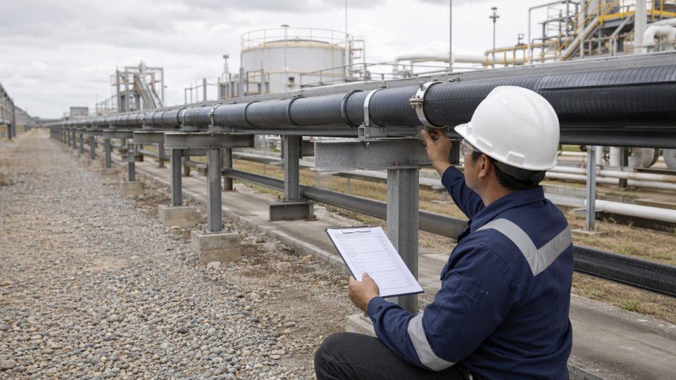
For project review or quotation support, send Jinda the voltage, cores, conductor size, installation route, ambient conditions, exposure hazards, required standard, certification needs, quantities, drum length preferences, destination, and delivery schedule. Jinda can review the application requirements and quote armoured cable suitable for the intended above-ground environment and compliance framework.