A shed supply that looks fine on current rating alone can still disappoint at 100 ft: lights flicker, tools start sluggishly, heaters pull the voltage down, and nuisance tripping gets blamed on the wrong kit. The expensive part is not just the cable; it is digging the trench twice, replacing undersized SWA, or discovering later that the circuit cannot support the load you actually use.
For a shed about 100 ft, or roughly 30 m, from the house, voltage drop often decides the armoured cable size before amp rating does. Many light-duty supplies land around 2.5 mm² or 4 mm² SWA, while workshop, heater, welder, or higher-load circuits commonly move to 6 mm² or 10 mm², subject to design verification.
The right answer depends less on the word “shed” and more on the load schedule, protective device, installation method, earthing arrangement, and whether this is a garden storage light or a small production bay in disguise. A few numbers change the decision sharply, so the sizing needs to be treated as an electrical design choice, not a shopping-list guess.
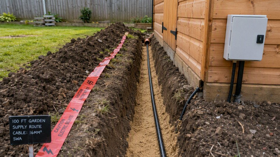
Shed load and diversity
A shed supply should be sized from the expected demand profile, not from the fact that the building is “only a shed.” At 100 ft, a lighting circuit and one convenience socket may be a light load, while heating, compressors, welders, hot tub equipment, or EV preparation can move the design current into a completely different class before cable size is even checked for voltage drop.
The first calculation is simple: list the loads, convert watts to amps, then decide which loads can realistically run together. For a UK single-phase supply, use 230 V as the working basis unless the designer has a better site-specific value.
For a single-phase 230 V shed supply, current in amps is estimated by dividing load in watts by 230, before applying diversity and design margin.True
This follows P = V x I for resistive or near-unity power-factor loads. Motors, welders, inverters, and electronic equipment may need allowance for starting current, power factor, and manufacturer data.
Typical examples:
| Connected load | Approximate current at 230 V | What it feels like in shed terms |
|---|---|---|
| 1 kW | 4.3 A | Lighting, battery chargers, a small tool, or a dehumidifier class load |
| 3 kW | 13 A | A fan heater, kettle-sized load, or one heavy socket appliance |
| 7 kW | 30.4 A | EV-related provision, substantial heating, or a larger dedicated load |
Those numbers are not cable sizes. They are the start of the design current.
Common shed demand levels
Shed use cases fall into distinct demand bands. Mixing them up is where many undersized garden supplies begin.
- Lighting and one socket: Usually the lightest case. LED lighting is modest, and the socket may only serve a mower charger, radio, laptop, or occasional small tool. A 13 A light-duty supply may be enough if the owner genuinely accepts that limitation.
- Garden tools and chargers: Cordless tool chargers draw little individually, but hedge trimmers, pressure washers, and mowers can create short higher loads. The awkward bit is nuisance tripping or voltage sag when a motor starts while other loads are already on.
- Freezer or dehumidifier: The running load may look small, but it can be continuous or seasonal. A freezer compressor cycling on a frosty morning is not the same design problem as a drill used for ten seconds.
- Small workshop: Bench saw, dust extractor, task lighting, chargers, and maybe a small heater. Not every item runs together, but in practice the extractor and saw often do, and someone will plug in a heater because cold hands are useless hands.
- Electric heating: This is often the load that dominates the design. A 2 kW or 3 kW heater can run for long periods, so it uses cable capacity continuously and leaves less headroom for tools.
- Compressor: The running current may be acceptable, but the starting current can be several times higher for a short period. Long cable runs make this more sensitive because voltage drop during starting can make the motor pull harder and start poorly.
- Welder: Do not size this from a casual plug rating alone. Welding sets vary widely by input current, duty cycle, power factor, and supply requirements; the nameplate and manual matter.
- Hot tub support equipment: Pumps, blowers, controls, and heaters need proper load data. If the hot tub heater is part of the supply, the demand can jump sharply and may need a dedicated design rather than being treated as a normal shed socket.
- Future EV or battery system preparation: This is not a casual spare socket. Even if the charger, inverter, or battery equipment is not being installed now, the route, cable, earthing approach, protection, and consumer unit capacity need to be planned from the start.
Diversity is useful, but it is not permission to guess low
Diversity means the design does not always have to equal the sum of every nameplate load. A shed with lights, two chargers, a small radio, and a lawnmower does not normally draw everything at full load all day. A workshop is different: saw plus dust extractor plus lighting plus compressor recharge is a believable combination, and if there is a heater in winter, that heater may already be using 9 A to 13 A before the first tool starts.
The mechanism matters. Continuous loads warm the cable and protective device over time; starting loads create short voltage dips and magnetic-trip stress; electronic loads may add leakage current or sensitivity to poor supply quality. A cable that looks adequate for steady current may still give poor service if the motor at the far end struggles to start because the volt drop rises exactly when the load current peaks.
The design current should reflect the heaviest credible operating condition, not the most convenient appliance list written on day one. That does not mean designing every garden shed like a commercial workshop. It means being honest about how the space will be used over the next several years.
There is a cost trade-off here. Larger SWA cable costs more, is stiffer, needs larger glands, may need more generous bends, and takes a little more care to terminate neatly in small enclosures. The saving from going smaller can disappear quickly if the cable is buried under paving, decking, planting, or a concrete path and later has to be replaced. In my experience, civil disturbance and labour usually hurt more than the original difference between common planning sizes such as 2.5 mm², 4 mm², 6 mm², and 10 mm².
A common misunderstanding is that the supply can be “upgraded later” by fitting a larger breaker. It cannot be done safely unless the original cable current rating, voltage drop, earth fault loop impedance, RCD arrangement, glands, containment, consumer unit capacity, and installation method were all designed for that higher rating. The breaker protects the cable; it does not magically improve it. If future workshop equipment, electric heating, hot tub equipment, EV charging, or battery hardware is plausible, that future load belongs in the design discussion before the trench is closed.
Voltage drop at 100 ft
At roughly 100 ft, or about 30 m, voltage drop often becomes the sizing check that pushes a shed supply above the smallest cable that would otherwise carry the current. A 2.5 mm² SWA may be fine for a modest light-and-socket load, but the same run feeding heaters, machinery, or regular high-current loads can justify 4 mm², 6 mm², or even 10 mm² after calculation.
Voltage drop is not a mysterious cable derating factor. It is simply the voltage lost as current flows through the resistance of the conductors. The shed is at the far end of that resistance, so the more current you draw and the longer the route, the lower the voltage available at the consumer unit, sockets, lights, tools, chargers, or controls in the shed.
That is why the answer changes with distance. A 13 A load close to the house and a 13 A load at the bottom of the garden do not see the same supply conditions, even if the protective device is identical.
A 100 ft shed cable run is about 30 m, and at that distance voltage drop can control cable size before current-carrying capacity does.True
100 ft converts to approximately 30.5 m. For small outdoor submains and final circuits, the current rating of a cable may be adequate while the voltage drop at the remote end is still too high for the intended load or applicable wiring rules.
What is actually dropping?
In a single-phase shed supply, the current leaves on the line conductor and returns on the neutral conductor. Both conductors have resistance, and the voltage available at the shed end is reduced by the combined effect of that circuit resistance. Cable tables normally account for this in their published voltage drop values, so you should not casually double the route length unless you are calculating from conductor resistance values directly.
The practical calculation is usually:
voltage drop = tabulated mV per amp per metre × design current × route length ÷ 1000
For example, the designer takes the correct millivolt-per-amp-per-metre value for the chosen cable size and installation conditions, multiplies it by the design current, multiplies again by the route length in metres, and converts millivolts to volts. That result is then checked against the allowed voltage drop for the circuit type and supply arrangement.
For UK work, electricians commonly check against BS 7671 voltage drop requirements, often discussed as tighter for lighting than for many other final uses. Do not treat an internet rule of thumb as a design approval; the current edition of the wiring regulations, the earthing arrangement, the circuit origin, and the actual load all matter.

Why 30 m is a nuisance distance
A 30 m garden run is not a transmission line. It is not extreme, and plenty of shed supplies are installed successfully at that distance. The nuisance is that it sits in the zone where small cable sizes can look acceptable on current rating but start to look weak once the load is more than occasional lights and a drill charger.
A typical light-duty shed might have:
- LED lighting
- One or two socket outlets for hand tools
- A battery charger
- A small freezer or garden equipment charger
- Occasional use rather than full-load operation all day
In that sort of case, a calculated design current may be low enough that 2.5 mm² SWA is still technically possible, provided the protective device, installation method, earthing, fault protection, and voltage drop all check out. The danger is copying that size into a different shed that has a very different load profile.
A workshop shed is a different animal:
- Electric heater or fan heater
- Compressor
- Bench saw, planer, grinder, or welder
- Dust extractor
- Multiple tools starting and stopping
- Lighting that must not flicker every time a motor starts
- Freezer or electronics that dislike low voltage
Here, the voltage drop rises in direct proportion to current. Double the design current and, with the same cable and route, you double the voltage drop. That is the mechanism that catches people out. The cable has not become “unsafe” in a thermal sense simply because the run is longer; it may still run cool enough. The shed equipment, however, may receive a sagging supply during normal use or an even deeper dip during starting.
Current-carrying capacity and voltage drop are separate checks: a cable can be thermally safe and still deliver an unsatisfactory voltage at the shed end.
Why larger SWA helps
Increasing conductor cross-sectional area lowers electrical resistance. Lower resistance means less voltage lost for the same current and the same length. That is why the practical planning sizes for a 100 ft shed feed often move through 2.5 mm², 4 mm², 6 mm², and 10 mm² rather than stopping at the first cable that appears to match the breaker rating.
The trade-off is commercial and physical as much as electrical. Larger SWA costs more, has a larger bending radius, needs larger glands and enclosures, and is less forgiving when you are trying to dress it neatly into a small garage consumer unit or adaptable box. Anyone who has wrestled 10 mm² SWA into a tight corner gland plate knows the material cost is not the only pain. On the other hand, undersizing the cable can create nuisance complaints for years: dimming lights, slow-starting motors, chargers dropping out, or the owner later discovering that the shed cannot support the workshop they actually want.
A simplified selection pattern often looks like this:
| Intended shed use at about 100 ft | Voltage drop tendency | Likely design implication |
|---|---|---|
| LED lights and very occasional small tools | Low | 2.5 mm² may be possible after full checks |
| General sockets, chargers, small garden workshop | Moderate | 4 mm² is often investigated rather than assuming 2.5 mm² |
| Heaters, compressor, heavier tools, sustained loads | Higher | 6 mm² commonly enters the discussion |
| High-demand workshop, future expansion, long detours, EV-related loads | High | 10 mm² or a different supply strategy may need assessment |
Those are planning categories, not approvals. Installation method can change the current rating. Protective devices change disconnection and overload requirements. Soil conditions, grouping, insulation, and how the cable enters buildings can all affect the final design.
Equipment that exposes voltage drop quickly
Some loads tolerate modest voltage variation without drama. A basic resistive heater will simply produce a little less heat at lower voltage. Other loads show the problem faster, and these are the ones I ask about before accepting a small cable size for a long garden run.
Watch voltage drop closely where the shed will contain:
- Lighting circuits, especially if the design must meet the tighter voltage drop allowance commonly applied to lighting.
- Motors, because starting current can be several times normal running current, causing a temporary voltage sag.
- Compressors and pumps, where low voltage can increase starting difficulty and heat the motor.
- Freezers or refrigerators, especially in cold, damp outbuildings where compressor restart conditions may already be poor.
- Electronic controls, chargers, inverters, and power supplies, which may trip, derate, or behave unpredictably if the supply dips.
- Welders or large workshop tools, where the load is intermittent but severe enough to disturb the rest of the shed supply.
The motor case is worth spelling out. A cable sized only around steady running current may look reasonable on paper, but starting current creates a short, sharp voltage dip along the same cable resistance. If the dip is large enough, the motor takes longer to accelerate, draws high current for longer, and heats more than expected. In practice, that can feel like “the breaker is too sensitive” or “the compressor is getting old,” when the supply design is part of the problem.
Measure the route, not the garden
The length used in the voltage drop calculation is the actual cable route length, not the straight-line distance from the back door to the shed wall. This is a common source of underestimation, especially when the trench route is planned after the electrical estimate.
Include:
- Vertical drop from the house consumer unit or supply point
- Route through the house, garage, or external wall
- Down the wall to the trench depth
- Detours around patios, tree roots, drains, ponds, and retaining walls
- Sweeps and bends rather than sharp corners
- Rise up into the shed
- Internal run to the shed consumer unit or first enclosure
- Extra length required for termination, glanding, and future re-termination
A “100 ft” garden can easily become a 34 m or 38 m cable route once the installer avoids the soakaway, drops to a sensible burial depth, and enters the shed on the side that actually has space for the board. That extra length feeds directly into the voltage drop calculation.
The boundary on the usual advice is simple: if the shed load is genuinely small, the route is close to 30 m, and the installation is otherwise favourable, voltage drop may not force a large cable. Once the load becomes sustained, motor-heavy, heat-heavy, or likely to expand later, the design should stop treating 2.5 mm² as the default and run the voltage drop numbers before trenching.
Likely SWA cable sizes
For a shed roughly 100 ft from the house, the practical planning range is usually 2.5 mm² to 10 mm² SWA, depending on the load and how the circuit is protected. At this distance, do not treat the smallest cable that carries the current as automatically acceptable; voltage drop, fault loop impedance, installation method, and future use often push the selection up one size.
At about 100 ft, voltage drop can control SWA selection before ampacity on shed supplies.True
For many small buried or clipped SWA runs, the cable may be thermally capable of carrying the load, but conductor resistance over roughly 30 m can make voltage drop the tighter design check, especially on socket circuits, motors, heaters, and workshop tools.
Planning ranges for common shed uses
These sizes are planning examples, not a substitute for a design calculation. A qualified electrician still has to confirm current-carrying capacity, voltage drop, earth fault loop impedance, RCD requirements, disconnection time, burial depth, glands, earthing arrangement, and the applicable local wiring rules.
| Intended shed use | Estimated design current | Likely SWA size range | Typical protective device range | Notes for electrician verification |
|---|---|---|---|---|
| Lights only, small charger, very occasional socket use | Roughly 3-10 A | 2.5 mm² may be considered | Often 6-16 A | Check whether socket use is genuinely limited. Voltage drop and fault protection still need proving over the full route. |
| General garden shed with sockets, mower, battery chargers, small tools | Roughly 10-20 A | 4 mm² commonly considered | Often 16-25 A | A useful upgrade where 2.5 mm² is marginal on voltage drop or future load. Confirm installation method and RCD/RCBO selection. |
| Small workshop, heavier tools, compressor, modest heating | Roughly 20-32 A | 6 mm² commonly considered | Often 20-32 A | Often chosen where starting currents, heaters, or regular socket loads make margin worthwhile. Check motor starting voltage and loop impedance. |
| Larger workshop submain, future expansion, heavier heating, multiple circuits | 32 A and above, subject to design | 10 mm² or larger may be needed | Often 32-50 A or engineered as a submain | Cable becomes stiff and termination space matters. Enclosures, glands, isolators, and protective devices must be sized as a system. |
The protective device column is deliberately cautious. A breaker size is not a cable rating. The breaker has to coordinate with the cable, installation conditions, expected load, fault current, RCD protection, and the supply earthing system. I have seen perfectly decent cable choices become awkward because someone selected the consumer unit first and then discovered the gland plate, bend radius, and earth termination were never going to make a neat job.
2.5 mm² SWA: light-duty only, and not automatically wrong
2.5 mm² SWA can be a reasonable planning candidate for a low-current shed supply: lighting, a small battery charger, a radio, and occasional light socket use. It is where many homeowners want the answer to land because the cable is cheaper, easier to pull, easier to gland, and less irritating to dress inside a small weatherproof enclosure.
The limitation is that 100 ft is long enough for resistance to matter. A 2.5 mm² conductor may be acceptable on current capacity in one installation method, yet fail the voltage-drop check once the actual route length, load current, and circuit arrangement are calculated. If the shed later gets a pressure washer, fan heater, chop saw, or small compressor, the original “just lights and a socket” design can become the wrong design very quickly.
Use 2.5 mm² only after checking:
- Design current is genuinely low and controlled by a suitable MCB or RCBO.
- Voltage drop remains within the permitted limit for the connected loads.
- Fault protection and disconnection time are met at the shed end.
- The cable installation method does not derate it beyond the intended protective device.
- Socket outlet use is not being quietly upgraded by habit, which is what usually happens once power is available.
A light-duty shed circuit is one of the cases where a smaller cable can be good engineering rather than false economy. That stops being true once the socket is expected to behave like a small workshop supply.
4 mm² SWA: the common step up for a more useful shed
4 mm² SWA is often the first sensible upgrade when the shed is more than a light-and-charger outbuilding. For a 100 ft run, it gives more voltage-drop margin than 2.5 mm² while still being manageable for typical domestic-sized glands, small distribution boards, and practical trench routes.
This size suits many garden shed circuits where the owner wants sockets for:
- Garden tools
- Battery chargers
- A freezer or small appliance, where allowed and appropriate
- Bench tools used one at a time
- Low to moderate lighting
- Occasional maintenance equipment
The mechanism is straightforward: increasing conductor cross-sectional area reduces resistance, so less voltage is lost along the run at the same current. That helps tools start better, reduces nuisance issues with equipment sensitive to low voltage, and gives the electrician more room to coordinate the protective device. It does not make the circuit unlimited. If someone plugs in a 3 kW heater and a compressor at the same time, the cable size alone is not the whole problem; the circuit design current and breaker selection must match the expected use.
The trade-off is cost versus usefulness. 4 mm² costs more than 2.5 mm² and is slightly less pleasant to handle, but on a buried garden run the labour, trenching, reinstatement, and inspection often cost more than the copper difference. In practice, if there is any credible chance that sockets will see regular tool use, 4 mm² is frequently easier to justify than digging the route twice.
6 mm² SWA: workshop territory and sensible future margin
6 mm² SWA is a frequent planning size for a proper shed workshop, not just a storage shed with a light. It is commonly considered where the load may include heavier socket circuits, modest electric heating, dust extraction, a compressor, larger chargers, or equipment with noticeable starting current.
Motor loads deserve special attention. A compressor or saw may draw a starting current several times its running current for a short period. If the supply cable has too much resistance, the voltage at the shed end dips during starting, the motor struggles, the breaker may nuisance trip, and the equipment runs hotter than it should. A larger conductor does not cure a badly specified motor circuit, but it reduces one of the avoidable causes.
6 mm² also gives better options if the shed will have a small distribution board rather than one simple radial circuit. That might include:
- A lighting circuit
- A socket circuit
- An outdoor socket or garden equipment point
- A dedicated circuit for a fixed tool or heater, where properly designed
The downside is not just cable price. 6 mm² SWA needs more care with bending, clipping, gland selection, banjo or earth nut arrangements, and termination space. In a cramped plastic enclosure on a cold day, that difference is not theoretical. Cable that looks reasonable on a website can be a pig to dress cleanly if the gland entries, tails, and protective devices were chosen too small.
10 mm² SWA: heavier submain, expansion, and long-term property use
10 mm² SWA moves the project from “shed circuit” toward “small submain” thinking. It may be appropriate for higher loads, larger workshops, future outbuildings, heavier heating, multiple final circuits, or a long-term property upgrade where the trench is open once and the owner wants capacity available later.
The commercial logic can be sound. If excavation, paving, ducting, or landscaping dominate the project cost, paying more for cable may be cheaper than revisiting the job. The electrical design still has to justify it. Oversizing the cable does not remove the need for correct protective equipment, isolation, earthing, RCD strategy, labeling, and distribution board capacity at both ends.
The trade-off becomes mechanical and installation-related. 10 mm² SWA is stiffer, heavier, and less forgiving. It may require:
- Larger CW or BW glands, depending on indoor/outdoor gland requirements
- Bigger adaptable boxes or consumer unit entries
- More generous bend radii
- Better support along the route
- Larger terminals or intermediate jointing arrangements
- Careful planning where the cable enters a small shed wall or compact board
A heavy cable badly terminated is not a high-quality installation. If the enclosure cannot accept the gland properly, the armour is not bonded correctly, or the cores are forced into tight bends, the oversized cable has created a workmanship risk.
2-core versus 3-core SWA on single-phase shed supplies
For a single-phase shed feed, the live conductors are line and neutral. With 2-core SWA, one core is used for line and one for neutral, and the steel wire armour may be used as the circuit protective conductor where permitted and correctly verified. With 3-core SWA, one core can be line, one neutral, and the third used as a protective conductor, with the armour still bonded correctly.
The choice is not only about buying one less core. The protective conductor path has to carry fault current long enough and well enough for the protective device to disconnect within the required time. That depends on armour cross-sectional area, conductor material, gland continuity, earth loop impedance, supply earthing arrangement, and the protective device curve. In UK-style practice, using the armour as CPC can be acceptable when calculated and installed correctly, but many electricians prefer 3-core SWA for shed supplies because it gives a dedicated copper CPC and a more comfortable verification route.
There are also earthing complications with outbuildings, exported PME supplies, extraneous conductive parts, metal water pipes, and TT arrangements. Those are not cable catalogue decisions. They belong in the site design, and they are one reason online anecdotes can be actively misleading.
Why online cable-size anecdotes are risky
A post saying “I used 2.5 mm² and it works” or “always use 10 mm²” leaves out the variables that decide whether the installation is safe and compliant. Cable ratings change with:
- Copper versus aluminium conductor construction
- XLPE versus PVC insulation
- Buried direct, buried in duct, clipped direct, or run through insulation
- Soil temperature and thermal resistivity
- Ambient temperature in sheds and lofted routes
- Cable grouping with other circuits
- Protective device type, rating, and trip curve
- RCD or RCBO arrangement
- Radial circuit versus submain feeding a small distribution board
- Actual route length, including vertical drops and internal runs
- Earthing system and fault loop impedance at the shed end
A sensible planning conversation can start with 2.5, 4, 6, or 10 mm² SWA. The final selection has to end with the electrician’s calculation, the cable manufacturer’s data, the current wiring rules, and the actual route through the garden rather than a number copied from someone else’s shed.
Installation route and burial method
The route you choose can make the same SWA cable either durable for decades or troublesome within a few wet seasons. At roughly 100 ft, cable size may be driven by voltage drop, but installation conditions drive mechanical protection, heat dissipation, water exposure, inspection access, and whether the cable can ever be replaced without digging up half the garden.
SWA cable can usually be considered for outdoor shed supplies because its steel wire armour provides mechanical protection, but the armour does not remove the need for correct glands, earthing, burial practice, and code-compliant installation.True
This reflects common electrical installation practice. Final design still depends on the applicable wiring rules, protective device arrangement, earthing system, and the cable manufacturer's installation instructions.
Route options and what changes in practice
| Installation route | Main advantage | Main risk or design issue |
|---|---|---|
| Direct burial | Good heat dissipation into soil and no exposed duct to trap water | Harder replacement, higher reliance on correct trench depth, bedding, and route marking |
| Ducted underground run | Better replacement option and extra mechanical barrier | Ducts can collect water and may reduce heat dissipation compared with open soil burial |
| Surface clipped to a wall or fence structure | Easy inspection and simpler fault location | UV exposure, impact damage, poor support, and questionable suitability if fixed to unstable fencing |
| Wall entry into house or shed | Short but critical transition point | Water ingress, sharp bends, poor gland fit, damaged sheath, and lost armour continuity |
| Short above-ground transition | Sometimes unavoidable near walls, posts, or equipment | Vulnerable to strimmers, lawn mowers, boots, pets, and sunlight unless protected |
Direct burial is clean and thermally favourable when it is done properly. The soil acts as a heat sink, so the cable can often shed heat better than it would inside a congested duct. The trade-off is serviceability: if the cable is damaged later, replacement means excavation. In practice, that makes route discipline matter. A neat trench with suitable bedding, warning tape above the cable, and a recorded route is not paperwork theatre; it is what stops a future fence post auger or landscaper’s spade from becoming the fault-finding tool.
Ducting is attractive because buyers like the idea of pulling in a replacement cable. That can be valid, especially under patios, paths, and driveways where re-excavation is expensive. The catch is that underground ducts are rarely dry. Water gets in through joints, condensation, low points, or damaged ends, then sits around glands and sheath transitions if the route is badly detailed. Ducts can also change the cable’s thermal environment, so current-carrying capacity must be checked for the actual installation method rather than assumed from a direct-buried rating.

Trench planning before anyone starts digging
A good route survey is worth more than a thicker cable installed badly. Walk the garden with the owner or facilities person and mark the practical run before ordering materials.
Check these items before trenching:
- Roots and mature planting
Avoid major roots where possible. Cutting through a root system can damage trees, and roots can also move ducts and cables over time. - Future landscaping
Ask about planned patios, hot tubs, greenhouses, decking, drainage work, and fence lines. Shed supplies often fail because the original route was forgotten during later garden work. Paths and driveways
Cross hard surfaces at planned points, usually with stronger mechanical protection and a route that can be documented. Avoid shallow diagonal crossings that nobody will expect later.Other services
Maintain required separation from gas, water, telecoms, drainage, and any existing electrical services. The exact separation is code and site dependent, but bunching everything in one narrow trench is poor practice unless specifically designed.Access for termination
Leave enough working space at both ends for proper SWA glanding, testing, and future inspection. A gland crammed behind shelving inside a damp shed is a maintenance nuisance from day one.
Burial depth should not be guessed from internet rules of thumb. It is a local code and risk-assessment requirement, affected by location, likelihood of disturbance, surface use, and whether extra mechanical protection is used. The engineering principle is simple: the cable must be deep enough, protected enough, and clearly marked enough to avoid foreseeable damage during normal use and future digging. The exact depth should be verified against the current wiring rules and the authority or electrician responsible for the installation.
Details that decide long-term reliability
SWA is selected because the steel wire armour gives the cable mechanical strength, but the armour only works as part of a complete installation. Correct SWA glands, earth continuity, banjo or earth tags where required, weatherproof shrouds, and clean terminations are not optional finishing touches. A loose gland can let moisture track under the sheath; a poor armour connection can compromise fault protection; an over-tightened gland can damage the bedding or sheath.
Above ground, the concerns change. UV exposure can age unsuitable outer sheaths and plastic accessories. At the shed wall, thermal cycling works joints loose over years: summer sun heats the wall, winter moisture creeps into tiny gaps, then freeze-thaw movement opens them further. Rodents, strimmers, lawn mowers, and casual impact from stored tools are more common threats than most drawings admit. Short exposed sections should be mechanically guarded, properly clipped, and routed where people are unlikely to kick or cut them.
This installation-route advice stops holding if the shed supply is part of a larger outbuilding, commercial workshop, EV charging arrangement, or high-fault-level distribution system. At that point the cable route is no longer just a garden convenience issue; it becomes part of a coordinated electrical design, including protection, earthing, discrimination, voltage drop, and site safety documentation.
Protection, earthing, and compliance
A 100 ft shed supply is only properly sized when the cable, protective device, earthing path, RCD protection, and test results all work together. The breaker is not chosen by asking, “What is the biggest MCB this cable can survive?” It is chosen so the cable is protected against overload and faults, and so disconnection happens fast enough under the actual installation conditions.
Overcurrent protection has to match the installed cable
The protective device at the supply end must be coordinated with:
- Cable conductor size and material
- Installation method, including burial, ducting, insulation, grouping, and ambient temperature
- Design current of the shed load
- Voltage drop
- Earth fault loop impedance
- Prospective fault current at the origin and at the shed end
- Required disconnection time under the applicable wiring rules
That is why a 6 mm² SWA cable and a 32 A breaker may be a sensible pairing in one installation and a poor pairing in another. If the cable is clipped in free air for most of its route, it behaves differently from the same cable buried in a duct with other services and pulled through a warm plant room before it exits the house. Cable tables are not magic numbers; they depend on correction factors.
In practice, I dislike seeing shed feeds protected by “whatever spare breaker was in the board.” A Type B, Type C, or fuse-based protective device changes the earth fault loop impedance requirement. Long cable runs raise impedance, and a protective device that looks fine on current rating may not disconnect quickly enough during a fault at the far end of the shed.
The protective device must protect the cable as installed, not the cable as advertised in a catalogue.
RCD and RCBO protection for outdoor shed circuits
Outdoor and outbuilding circuits usually need residual current protection, especially where sockets, garden equipment, damp floors, metal tools, or portable appliances are involved. In UK-style installations, 30 mA RCD protection is commonly expected for socket outlets and many buried or outdoor cable arrangements, but the exact requirement depends on the circuit design and the current edition of the applicable rules.
An RCBO per circuit is often cleaner than putting the whole shed on one shared RCD. If a damp outside light fitting trips, it should not necessarily kill the freezer, alarm, or all workshop sockets. For a simple small shed, one RCBO-protected supply may be acceptable. For a workshop, separating lighting and sockets is usually worth the extra enclosure space and cost.
Nuisance tripping is not always a nuisance; sometimes it is the installation telling you that water has found a gland, a junction box has condensation, or a cheap outdoor socket has aged badly. I have seen plenty of “mystery trips” traced to a SWA gland left without a proper shroud or a bottom-entry box with no drain path.
Earthing the shed is not a detail to tidy up later
The earthing arrangement must provide a reliable fault return path and touch-voltage control. With SWA cable, the steel wire armour may be used as a circuit protective conductor only where regulations, cable data, termination quality, and fault calculations support it. Many designers still run a separate protective conductor core, or use a 3-core SWA for single-phase live, neutral, and CPC, because it removes some uncertainty and makes testing more straightforward.
Key checks include:
- Armour continuity through both glands
- Correct banjo, earth nut, or approved gland earthing method
- CPC continuity from origin to shed consumer unit
- Earth fault loop impedance at the farthest point
- Bonding requirements for any extraneous conductive parts
- Corrosion protection at outdoor terminations
- Mechanical protection where the cable rises from the ground
PME earthing deserves special care. Exporting a PME earth to a detached shed can be acceptable in some cases and problematic in others, particularly where the shed contains extraneous conductive parts such as metal water pipes, structural steel, outside taps, metal-framed equipment, or livestock-related installations. A broken PEN conductor is a low-probability, high-consequence fault, and the answer is not something to guess from a forum sketch.
Local guidance, BS 7671 requirements, distribution network operator rules, and the site conditions all matter here. Sometimes the design uses the exported earth with appropriate bonding. Sometimes a TT arrangement for the outbuilding is considered. The correct choice depends on measured conditions and the actual conductive paths around the building.
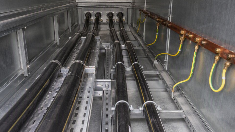
Shed consumer unit, isolation, and circuit layout
A shed consumer unit should be selected around the intended use, not just the smallest plastic box available. For a light-duty garden office, a small enclosure with local RCD or RCBO protection may be enough. For a workshop, separate circuits are usually better:
- Lighting circuit, so a tool fault does not leave the user in darkness
- General socket circuit
- Dedicated circuit for heater, compressor, welder, dust extractor, or EV-related equipment where applicable
- Outdoor socket or garden equipment circuit, if exposed to weather
- Spare way for future loads, if the supply cable and upstream protection can support it
A local switch-disconnector is good practice. It gives the user or electrician a clear way to isolate the shed for maintenance, water ingress investigation, machine installation, or emergency response. I prefer obvious local isolation over telling someone to walk back to the house and guess which breaker feeds the outbuilding.
Circuit segregation also helps fault-finding. If everything is on one final circuit, one damp fitting, one damaged extension lead, or one rodent-chewed cable can take down the whole shed.
Inspection, testing, and paperwork
The job is not complete when the lights turn on. A competent installer should inspect and test the circuit before energising and document the results where required.
Typical checks include:
- Continuity of protective conductors and bonding conductors
- Continuity of ring final conductors, if a ring circuit is used
- Insulation resistance between live conductors and to earth
- Polarity at the origin, shed board, switches, sockets, and fixed equipment
- Earth fault loop impedance
- Prospective fault current
- RCD or RCBO trip time and trip current tests
- Functional operation of isolators and protective devices
- Verification of cable route, depth, warning tape, glands, supports, and mechanical protection
For UK work, BS 7671, Part P building control notification in applicable domestic situations, utility requirements, and any special location rules may all be relevant. Outside the UK, the same engineering principles remain, but the legal route changes: local electrical codes, permit requirements, inspection rules, and utility earthing practices take priority. A cable size estimate is useful for planning and procurement; compliance is proven only by a design checked against the governing rules and by test results from the installed circuit.
Cable specification for procurement
A purchase order that says “6 mm² armoured cable” is not a cable specification; it is only one parameter. For a shed feed, the buyer should specify the complete SWA construction, applicable standard, documentation package, drum requirement, and compatible accessories so the installer receives cable that can actually be terminated, tested, certified, and maintained.
For a low-voltage garden building supply, the procurement line usually needs the following details, not just the conductor size:
| Procurement item | What to specify | Why it matters on site |
|---|---|---|
| Conductor material | Copper or aluminium | Affects resistance, voltage drop, bending, termination method, and price |
| Conductor size | 2.5 mm², 4 mm², 6 mm², 10 mm², or engineered size | Must match design current, voltage drop, fault protection, and installation method |
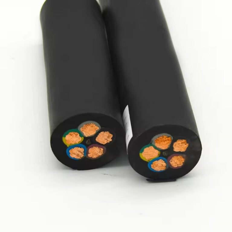
| Number of cores | Commonly 2-core, 3-core, 4-core, or 5-core depending on earthing and load arrangement | Wrong core count is expensive to correct once the trench is open |
| Voltage rating | Typically 600/1000 V for LV SWA, subject to project standard | Confirms suitability for fixed low-voltage distribution use |
| Insulation | XLPE or PVC, as specified | XLPE is often preferred where higher operating temperature rating is useful; PVC may be used where permitted and suitable |
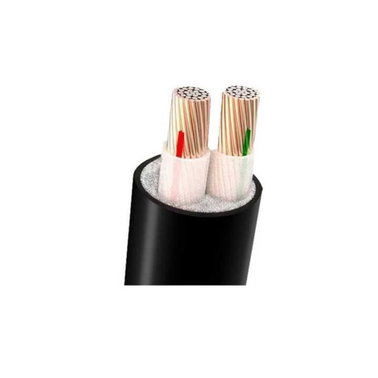
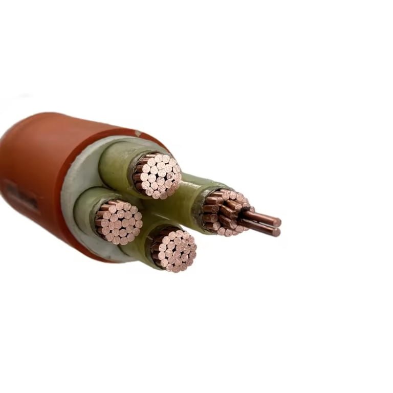
| Bedding and armour | Bedding layer plus steel wire armour for multicore cable | Provides mechanical protection and, where designed correctly, may be part of the earthing arrangement |
| Outer sheath | PVC or low-smoke zero-halogen material | PVC is common outdoors; LSZH may be required in occupied buildings, enclosed routes, or project specifications |
| Sheath colour | Usually black for external SWA, unless project marking calls for another colour | Helps UV resistance, identification, and consistency with site practice |
| Standard compliance | For example, UK-style LV SWA may be specified to BS 5467 for XLPE/PVC or BS 6724 for LSZH applications, where applicable | Prevents buying a visually similar cable that does not meet the required construction or test regime |
| Drum length and packaging | Exact length, cutting allowance, drum type, end sealing, handling marks | Avoids joints, short deliveries, damaged ends, and forklift damage during storage |
| Documentation | Test report, declaration or certificate of conformity, batch traceability, cable markings | Needed for handover files, inspection, warranty control, and procurement audit trails |
Conductor size alone is incomplete because two cables with the same mm² rating can differ in insulation system, sheath behaviour, standard compliance, marking, and termination compatibility. That difference shows up later as gland mismatch, failed inspection, missing paperwork, or an installer cutting back a cable that was never suitable for the enclosure entry.
In practice, a clear description might read something like: “600/1000 V multicore SWA cable, copper conductors, XLPE insulated, PVC bedded, galvanized steel wire armoured, black PVC sheathed, manufactured to the applicable LV armoured cable standard, supplied on one drum with factory test documentation and continuous sheath marking.” The actual conductor size and core count must come from the electrical design, not from the purchasing desk.
Copper versus aluminium is a procurement decision as much as an engineering decision. Copper gives lower resistance for a given cross-section, compact terminations, and familiar handling for most domestic and light commercial installers. Aluminium can reduce cable cost and weight on longer or larger feeders, but the cross-section normally has to increase to achieve comparable voltage drop and current capacity, and terminations must be aluminium-rated or bi-metallic where required. The saving can disappear quickly if the job needs special lugs, larger glands, bigger enclosures, or extra labour from an installer who is not set up for aluminium.
Accessories should be bought against the actual cable outside diameter and armour construction, not guessed from the nominal conductor size. Include:
- Correct SWA glands for indoor or outdoor use, including IP rating where needed
- Earth tags, banjos, locknuts, and shrouds
- Cleats or saddles sized to the cable diameter
- Warning tape, ducting, marker posts, or draw rope for buried routes
- Suitable enclosure entries, bushes, reducers, or adaptors
- Lugs, ferrules, heat shrink, and identification sleeves
- Crimping tools, torque tools, and test access required by the installer
For contractors, wholesalers, and project buyers, the cleanest procurement process is to issue the intended cable designation, route conditions, required standard, delivery length, documentation requirement, and accessory list together. Jinda, as an integrated cable manufacturer with R&D, production, technical support, and international supply capability, can support bulk SWA cable procurement, specification review, documentation, and long-term project supply where buyers need repeatable cable quality rather than one-off counter sales.
Cost, upgrades, and future capacity
A minimum compliant cable can be the cheapest purchase and still be the expensive decision if the garden route is difficult to reopen later. At roughly 100 ft, I usually treat the cable size as a lifecycle choice: pay only for today’s load if the shed will stay light-duty, but allow spare capacity if workshop use, heating, controls, or outdoor circuits are likely.
The visible cable price is only one cost driver. A buyer looking at 2.5 mm² versus 6 mm² or 10 mm² SWA will see the conductor price move, especially with copper markets, but the installed cost also includes:
- Conductor material and size, usually copper for smaller shed feeds, with aluminium more relevant to larger distribution runs.
- Number of cores, including whether a separate protective conductor is required by the design.
- Full route length, including vertical drops, bends, service loops, and waste allowance.
- Trenching, ducting, warning tape, sand bedding where specified, and reinstating paving, turf, gravel, or planting.
- SWA glands, shrouds, banjo or earth tags where used, adaptable boxes, cleats, and enclosure entries.
- Consumer unit work, RCD or RCBO provision, labelling, inspection, testing, and certification.
On many domestic outbuilding jobs, the trench and electrician’s time cost more than the incremental jump from one sensible cable size to the next. That is why modest oversizing often has a sound economic case. If a shed may later gain a small lathe, compressor, electric heater, freezer, irrigation controls, CCTV, gate automation, or extra garden lighting, installing a cable with spare voltage-drop and current capacity now is usually cheaper than digging the same route twice.
For a 100 ft shed supply, voltage drop and future load often justify considering the next practical SWA size rather than selecting the absolute minimum conductor size.True
At about 30 m, voltage drop becomes a material design constraint, and replacement after burial can involve trenching, reinstatement, testing, and certification costs beyond the cable price itself. The final size still depends on load, installation method, protection, and local code verification.
There is a practical limit. Larger SWA is stiffer, heavier, harder to pull through duct, less forgiving around corners, and more awkward to gland neatly into small plastic enclosures. I have seen tidy designs become ugly on site because nobody checked the bend radius, gland clearance, or terminal capacity before ordering the cable. Spare capacity should be designed, not improvised later by fitting a larger breaker to an undersized circuit.
The sensible approach is to decide the likely ten- or twenty-year use of the shed before the trench is opened. Outdoor cable, correctly specified and installed, can serve for decades; replacing an undersized buried supply after the patio is laid is the kind of saving that rarely feels clever later.
Frequently asked questions
Can I run a shed from a normal plug?
For temporary, light-duty use, a plug-in extension may run a lamp, battery charger, or small hand tool if the equipment, lead, RCD protection, and weather exposure are properly controlled. That is not the same as a permanent shed supply. A fixed outdoor circuit should be designed, installed, protected, tested, and certified as a fixed electrical installation, not treated as a long extension lead through the flower bed.
Is 2.5 mm² armoured cable enough for 100 ft?
Sometimes, but only for limited loads and only after checking the full circuit. At roughly 30 m, voltage drop can become the limiting factor before the cable’s basic current rating does. A 2.5 mm² SWA feed may suit a modest lighting and socket load, but the breaker size, installation method, earth fault loop impedance, RCD arrangement, and permitted voltage drop all need checking against the actual design.
Should I use 4 mm² or 6 mm² SWA?
4 mm² is often the practical middle ground for a small shed where the load is known and unlikely to grow. 6 mm² gives better voltage drop margin and more future capacity for heavier tools, heating, or a small workshop, but it costs more, is stiffer to terminate, and needs larger glands, boxes, and sometimes more patience from the installer. If the trench is already open, upsizing is usually cheaper than digging twice.
Do I need 3-core SWA for a shed?
Not universally. Some designs use 3-core SWA with one core as the circuit protective conductor; others use 2-core SWA with the steel wire armour correctly glanded and verified as the protective conductor. The right choice depends on earthing system, fault protection, armour continuity, gland quality, cable length, and the electrician’s design calculations. In practice, many contractors prefer 3-core for a cleaner, more predictable earth path.
Can SWA be buried without ducting?
SWA is made for mechanical protection and is commonly buried direct, but that does not mean “throw it in a shallow slit and forget it.” The route, burial depth, sand bedding or selected backfill, warning tape, bends, drainage, and protection where it rises from the ground all matter. Local rules and the project specification decide whether ducting is required or just good practice.
Does the shed need its own consumer unit?
It depends on how many circuits the shed needs and how the supply is protected at the house end. A single small circuit may only need suitable local isolation, while a shed with separate lighting, sockets, machinery, or outdoor loads may justify a small consumer unit or distribution board. Protective device coordination matters; nuisance tripping in the house every time a damp tool faults is poor design.
Can an electrician certify cable I installed myself?
Maybe, but do not assume it. In many jurisdictions, an electrician must inspect the route, burial method, terminations, glands, earthing, and test results before anything is concealed. Some will not certify work they did not control because they carry responsibility for the finished installation. If you plan to dig the trench yourself, agree the inspection points before the cable goes in.
Your cable schedule verification
Before cable is ordered, treat the shed supply as a small cable schedule, not a guess at conductor size. Confirm the design load, measured route length, installation method, voltage drop allowance, protective device, earthing arrangement, and future capacity margin; at roughly 100 ft, a change in any one of those can move the job from one common SWA size to the next.
Use this final check before committing money or trenching the garden:
- Load list: lights, sockets, heater, compressor, tools, charger, welder, freezer, or any equipment with high starting current.
- Measured route: actual cable run from origin to shed consumer unit or termination point, including rises, bends, and spare tail length.
- Proposed cable size: for example, 2.5 mm², 4 mm², 6 mm², or 10 mm² only after design verification.
- Core count: 2-core, 3-core, or 4-core as required by the earthing and circuit arrangement.
- Cable construction: conductor material, XLPE or PVC insulation, bedding, steel wire armour, outer sheath colour, and voltage rating.
- Installation method: direct burial, duct, clipped route, wall entry, gland position, warning tape, and mechanical protection.
- Protection plan: MCB, fuse, RCBO, RCD arrangement, rating, breaking capacity, and discrimination with upstream devices.
- Earthing method: armour use, separate CPC, bonding needs, TT/TN considerations, and gland continuity.
- Accessories: CW glands, shrouds, banjos or earth tags, cleats, warning tape, duct, junction box, and shed consumer unit.
- Documentation: applicable standard, test certificates, cable markings, packing list, and any project quality records.

Homeowners should use these points to brief a qualified electrician, not to self-certify a final design. Contractors and procurement teams should turn the verified design into a formal cable schedule for quotation, production planning, delivery, and quality documentation.
For SWA cable procurement support, contact Jinda with the cable size range, required standard, voltage rating, core count, total length, packaging requirement, and project country. Jinda’s technical and sales teams can review the specification details and support quotation and supply planning for armoured cable orders.