Specify the wrong cable type on a purchase order — or let a site electrician substitute “something similar” from the storeroom — and the consequences land fast: insulation breakdown under load cycling, premature joint failure, nuisance tripping that shuts down a production line at the worst possible moment. Replacement isn’t just the cost of cable; it’s crane time, splicing labor, potential requalification of the circuit, and in some jurisdictions a mandatory inspection before re-energization. Getting the cable selection right the first time is genuinely cheaper than fixing it later.
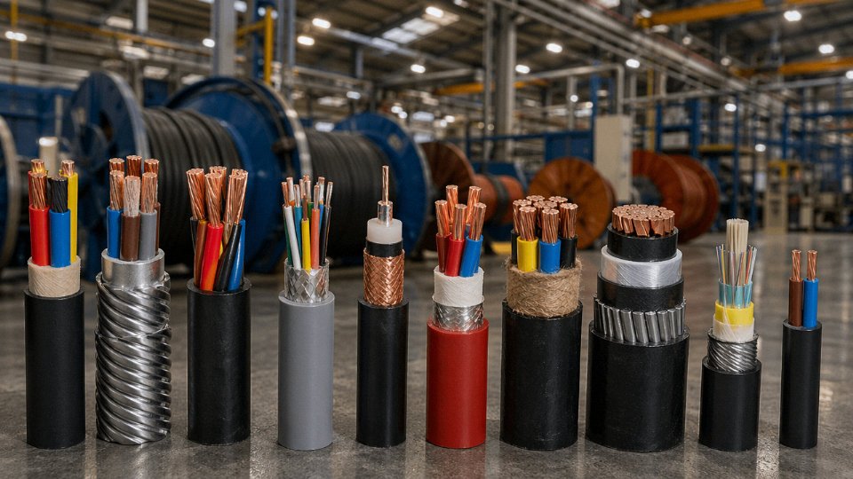
The ten main types of cable used across industrial, commercial, and infrastructure applications are: low-voltage power cable, medium- and high-voltage power cable, armored cable, flexible control cable, instrumentation cable, fire-resistant and flame-retardant cable, mining cable, submarine cable, building wire (such as THHN/THWN or NYY), and fiber optic cable. Each type is defined by its conductor material, insulation system, mechanical protection, and the electrical environment it’s designed to handle.
The global wire and cable market was valued at roughly USD 225 billion in 2023 and is tracking toward USD 300 billion by 2030 — growth driven by grid expansion, EV infrastructure, and industrial automation, not by any single product. Low-voltage power cables alone account for somewhere between 35 and 40 percent of shipments by revenue, which tells you where the bulk of procurement decisions actually concentrate. But the other nine types carry their own engineering logic, their own failure modes, and their own procurement traps. Worth understanding what separates them.
Type 1 — Low-Voltage Power Cable (Up to 1 kV): The Backbone of Building and Industrial Wiring
Low-voltage power cable is, by volume, the most produced cable category on the planet. Estimated at 35–40% of global cable shipments by revenue, it shows up in virtually every project — substations, commercial fit-outs, industrial facilities, infrastructure civils. Getting the construction right at specification stage is where most of the real decisions happen, and getting it wrong usually surfaces as heat, voltage sag, or an armoring failure you don’t discover until a cable pulls apart during installation.
Construction: What’s Inside and Why It Matters
The conductor is the first decision. Copper dominates smaller cross-sections — 1.5 mm² up to roughly 120 mm² — because of its lower resistivity and easier termination. Above that threshold, aluminum becomes cost-competitive on large feeder runs; a 630 mm² aluminum conductor carries roughly the same current as a 400 mm² copper equivalent at about 40–50% of the copper material cost, depending on commodity pricing at time of order. The catch is that aluminum demands correct compression lugs, anti-oxidant compound at every joint, and more careful bending radius management. Skip any one of those and you’re dealing with a high-resistance joint that heats over months before it fails.
Insulation is almost always XLPE or PVC. XLPE tolerates higher continuous operating temperatures — 90 °C versus 70 °C for standard PVC — which translates directly to higher ampacity for the same conductor cross-section. For a main distribution feeder where you’re trying to squeeze the most capacity through a defined conduit space, XLPE is usually the right call. PVC is cheaper, adequate for most final circuits, and still widely specified in cost-sensitive markets.
Armoring choices split along installation environment. Steel wire armour (SWA) is standard for direct burial, sub-floor routes, or anywhere mechanical damage is a credible risk. Steel tape armour (STA) sees use in some European specs and offers crush resistance without the same pulling tension tolerance. For indoor installations in clean, cable-managed environments — office fit-outs, raised-floor data suites — unarmoured cable is perfectly normal and keeps termination work simpler.
Outer sheath material is where fire performance requirements force the spec. Standard PVC works for most industrial and outdoor applications. LSZH (low smoke zero halogen) sheath is specified for enclosed public spaces, tunnels, and marine applications, where halogen gas release during a fire is a serious life-safety concern. The cost premium for LSZH is typically 10–20% over an equivalent PVC-sheathed cable, depending on the compound batch and order volume.
Standards Alignment Across Export Markets
IEC 60502-1 is the baseline international standard and covers cables up to 1 kV through its test requirements for insulation, sheath, and armoring. The UK market layers BS 5467 (SWA, PVC sheathed) and BS 6724 (SWA, LSZH sheathed) on top of that framework. France specifies NF C 32-321 for its low-voltage distribution network, with particular attention to conductor class and sheath compound specs. These aren’t interchangeable — a cable built purely to IEC 60502-1 will often need additional test documentation before a UK DNO or a French contractor accepts it on site.
Jinda's LV power cables are manufactured across production lines certified and tested to IEC 60502-1, with export documentation supporting CE marking, KEMA type-test records, and SASO certification for Gulf Cooperation Council marketsTrue
Multi-standard certification is a stated capability of Jinda's manufacturing and QA system, enabling single-source supply for contractors running parallel projects across European, UK, and Middle Eastern jurisdictions
Conductor Sizing in Practice
Sizing is a three-step process in reality, even though it often gets compressed into a single table lookup. Start with ampacity from the relevant installation method column — IEC 60364 tables or BS 7671 appendix tables depending on jurisdiction. Then apply derating: cables grouped in a trunking or duct lose heat dissipation efficiency, and in hot climates (ambient above 30 °C is enough to shift the numbers noticeably), additional temperature correction applies. A cable that looked adequately sized at 25 °C ambient in a northern European design might be running at 97% of its rated capacity in a Gulf installation during summer — that margin disappears fast when you add grouping factors on top.
Voltage drop is the other constraint that bites on long runs. Final circuits are typically held to ≤ 4% voltage drop under IEC 60364; some specs tighten that to 3% for sensitive equipment loads. A 16 mm² four-core copper XLPE cable on a 60-meter run feeding an office lighting board is straightforward. That same 16 mm² cable feeding a 45 kW motor across 120 meters needs a voltage drop check before you sign off the spec — and more often than not, you end up stepping up to 25 mm² or 35 mm² to stay inside the limit rather than because of ampacity.
The practical selection scenario illustrates the range well. A 630 mm² single-core aluminum XLPE SWA cable for a substation incomer feeder is a direct-burial, high-current, long-run application where material cost per meter dominates and termination work is done by specialist jointers. A 4-core 16 mm² copper XLPE LSZH unarmoured cable for an office ceiling void is a short-run, fire-performance-sensitive application where ease of installation and smoke behavior matter more than material savings. Both are “LV power cable.” The construction, handling, and termination requirements share almost nothing in common.
Type 2 — Medium and High Voltage Cable (3.6 kV to 500 kV): Engineering the Power Grid’s Critical Links
Step off the factory floor and into a substation yard, and the engineering conversation changes completely. The tolerances tighten, the consequences of a specification error compound over decades, and the accessories suddenly matter as much as the cable itself. MV and HV cables are not simply “bigger” low-voltage cables — they are a fundamentally different class of engineered product.
The Voltage Classification Ladder and Why It Matters
The IEC 60183 and IEC 60840 framework divides this territory into distinct bands, each demanding a different insulation approach. Medium voltage runs from 3.6/6 kV up through 12/20 kV and tops out around 26/35 kV — the distribution backbone of industrial parks, wind farms, and urban networks. High voltage covers 66 kV to 220 kV, the transmission tier. Above 330 kV you are in extra-high and ultra-high voltage territory (EHV/UHV), where cable design is essentially custom engineering for each project.
Why does each band require different insulation engineering? The short answer is electrical stress. Insulation thickness scales roughly with voltage, but the design challenge is not just bulk dielectric strength — it is controlling the electric field at the conductor surface and eliminating any voids or contamination that would initiate partial discharge. At 11 kV a small void is a slow degradation path. At 220 kV it is a failure mechanism.
XLPE Has Largely Replaced PILC — Here’s Why
Paper-insulated lead-covered (PILC) cable held the MV market for most of the twentieth century, and you still encounter it in older urban infrastructure where replacement budgets lag. In new projects, cross-linked polyethylene (XLPE) has displaced it almost entirely, for good reason.
XLPE insulation delivers dielectric strength in the range of 20–25 kV/mm, considerably better than impregnated paper, and its partial discharge inception voltage is substantially higher under the same conductor geometry. Moisture resistance is the other decisive factor: PILC depends on its lead sheath remaining intact; once the lead cracks — from ground movement, thermal cycling, or a careless excavator — moisture ingress begins and the clock starts on a fault. XLPE is inherently moisture-tolerant, though for buried HV cables a corrugated aluminum or lead sheath is still added for mechanical and radial water-blocking reasons. Over a 30–40 year asset life, lifecycle costs for XLPE installations typically run 15–30% lower than equivalent PILC, mostly because jointing labor and emergency repair time drop significantly.
Anatomy of a 132 kV Single-Core XLPE Cable
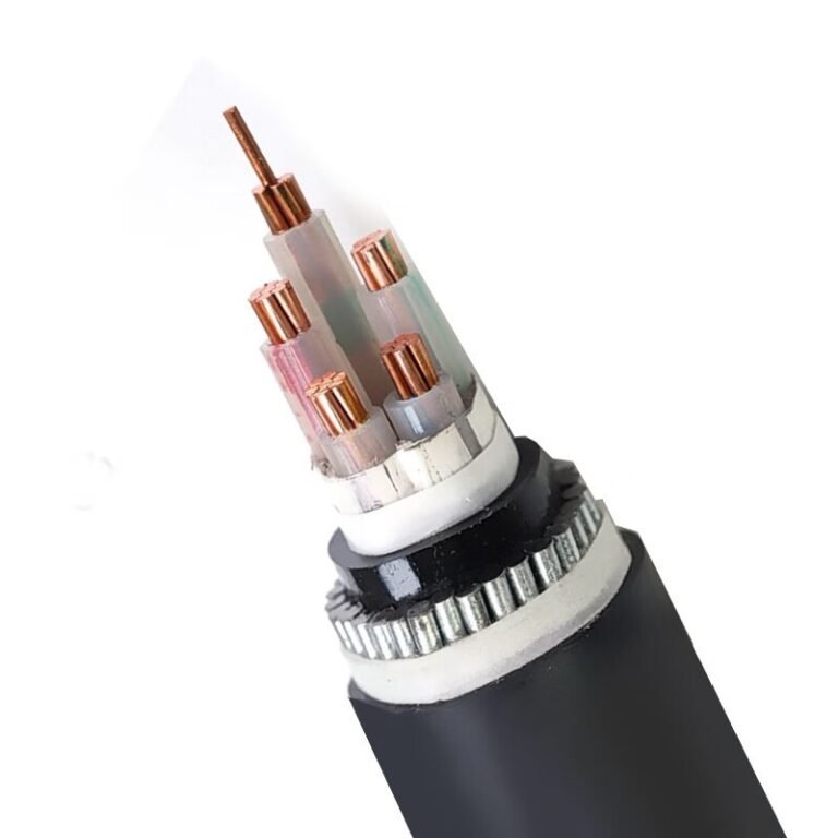
Working outward from the center: the stranded copper or aluminum conductor (sector-shaped or circular, depending on installation grouping) carries current. Directly over it sits the conductor screen — a semiconducting compound layer whose job is to smooth the electric field so no sharp points on the conductor strands create localized stress concentrations. The XLPE insulation follows, its thickness calibrated to the rated voltage and the required partial discharge performance class. Over the insulation, the insulation screen mirrors the conductor screen, again for field control. Then comes the metallic sheath — either extruded lead or helically applied copper wires — which provides the return path for fault current and blocks radial moisture. Bedding protects the sheath during armoring, the armor (usually flat steel wires for single-core, to avoid induced circulating currents that would occur with steel tape on AC circuits) takes mechanical load, and the outer sheath in polyethylene or PVC closes the system.
Remove or compromise any single layer and the cable will eventually fail. This is not a product where you can value-engineer individual components in isolation.
Joints and Terminations: The Weak Points Nobody Talks About Enough
In practice, most HV cable failures occur at terminations and joints, not along the cable run itself. A correctly manufactured cable connected with an under-specified accessory is a liability. Prefabricated cold-shrink joints have largely replaced field-taped solutions for MV work — installation is faster, human error is reduced, and performance is more repeatable. Heat-shrink accessories remain common at 12–35 kV. Above 66 kV, slip-on or factory-assembled push-on joints dominate, and every accessory must be specified to the same voltage class and partial discharge standard as the cable.
Accessories must be voltage-class matched to the cable and supplied from a qualified manufacturer — mixing cable classes or sourcing terminations from unverified suppliers is a documented cause of HV cable failures in grid projects.True
IEC 60840 and IEC 62067 require cable and accessories to be type-tested as a system; mismatched accessories alter the electric field geometry at the joint interface, creating partial discharge sites that grow to failure over months or years.
Jinda’s MV and HV Capability
Jinda’s standard production range covers MV cables through 35 kV ex-stock across copper and aluminum conductor options, with XLPE insulation built to IEC 60502-2 and relevant national standards. Higher voltage projects — 66 kV through transmission-class ratings — are handled on a project-order basis with full documentation support. Renewable energy installations, including wind and solar farm collection networks and grid connection feeders, have been among the more demanding supply cases in recent years, where cable routing, armor specification, and delivery scheduling across multiple cable drum lengths all need coordinating from a single supply point.
Type 3 — Control and Instrumentation Cable: Precision Signal Integrity in Harsh Environments
Engineers often lump control and instrumentation cable together in specs, and that’s a mistake that shows up later as ground loops, signal drift, or nuisance trips on a DCS. They’re related but genuinely different products solving different problems.
Control Cable vs. Instrumentation Cable: Not the Same Thing
Control cable is the workhorse of switching circuits — think relay outputs, solenoid valve commands, motor starter interlocks. Typically multi-core (anywhere from 4 to 37 cores, sometimes more), rated at 300/500 V or 450/750 V per IEC 60227 or national equivalents, with PVC or LSZH insulation over plain or stranded copper conductors. The signal levels are relatively robust: 24 VDC digital, 110/220 VAC switching. Noise immunity matters, but it’s forgiving compared to analog instrumentation.
Instrumentation cable carries a different load entirely. A 4–20 mA loop from a pressure transmitter sitting 200 meters from the control room represents a signal range of 16 mA across that span. Inject even a few milliamps of interference and you’ve shifted your reading by a meaningful percentage of span — enough to cause a false alarm or, worse, mask a real process deviation. That’s the failure mode that justifies the added cost of proper screening.
Shielding Options: What Each Actually Does
The choice of shield architecture isn’t cosmetic. It directly determines how well the cable rejects capacitively coupled and inductively coupled interference, and the difference between options is large enough to matter in practice.
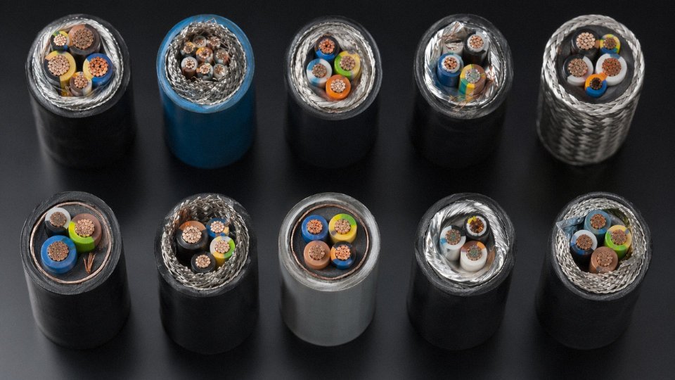
An overall aluminum-foil shield (typically bonded to a drain wire) gives good coverage against electric field interference — capacitive coupling from adjacent power cables — and is the minimum you’d specify for a general instrumentation run in a clean industrial environment. Transfer impedance at low frequencies is reasonable, though foil alone starts losing effectiveness above roughly 1 MHz.
Individually shielded pairs take this further. Each signal pair gets its own foil screen, referenced to its own drain wire, which allows you to ground each loop independently and break the common-impedance path that causes ground loops between transmitters at different earth potentials. In a large petrochemical plant where transmitters are scattered across multiple earthed structures, this configuration isn’t a luxury — it’s the only way to keep analog readings stable.
A braided copper shield provides lower transfer impedance at higher frequencies compared to foil alone, and it handles mechanical flexing far better. You’d see this specified on cables going to vibrating machinery, or where the cable routing involves repeated movement. The trade-off is cost and slightly reduced coverage percentage compared to a tight foil.
The combined foil-plus-braid construction covers both ends: the foil gives near-100% coverage for electric field rejection, the braid handles high-frequency magnetic fields and mechanical durability. This is what you’d see on cables feeding into variable-frequency drive panels or running near large transformer banks where both field types are present simultaneously.
Pair and Triple Configurations for Sensor Circuits
Thermocouples, RTDs, and most analog transmitters run on twisted pairs — the twist rate matters because tighter lay lengths improve rejection of low-frequency magnetic interference. RTD circuits, particularly three-wire and four-wire configurations, sometimes use triplexed conductors to balance the lead resistance. Triaxial configurations show up in high-precision measurement circuits where an outer guard conductor sits between the signal pair shield and the overall cable shield, further suppressing leakage currents.
Standards That Actually Appear in Plant Specifications
IEC 60332 flame retardancy requirements appear in virtually every process plant instrument cable spec — usually IEC 60332-3 (category C or B for bunched cable tray installations). Offshore and marine projects layer IEC 60092-350 on top of that, which adds requirements for oil resistance, mud resistance, and halogen-free sheath compounds that ordinary industrial cable doesn’t meet. Where cables pass through fire-rated bulkheads or must maintain circuit integrity during a fire event, IEC 60331 (circuit integrity at elevated temperature) gets specified — common in power station instrumentation and safety system wiring.
Individually shielded instrumentation pairs significantly reduce ground loop interference compared to overall-shield-only designs in multi-drop analog signal installations.True
Individual pair shields allow independent grounding of each signal loop, isolating earth potential differences between field instruments and the control room — a well-established principle in industrial instrumentation practice per IEE/ISA wiring guidelines.
Manufacturing Precision for Screened Instrumentation Cable
At Jinda’s production facilities, conductor stranding for instrumentation cable follows tight lay-length tolerances — deviation in twist rate affects both the electrical balance of the pair and the cable’s capacitance consistency, which matters when you’re specifying capacitance per meter for long analog runs. Foil application is monitored for overlap percentage and bonding integrity to the drain wire; a foil screen with poor drain wire contact is essentially useless in practice, regardless of what the drawing shows. Finished cables undergo impedance and capacitance testing per IEC 60092 and customer-specific protocols before release, because a capacitance mismatch between cable batches on the same signal loop can cause subtle calibration offsets that take a commissioning team days to chase down.
Type 4 — Fire-Resistant and Low-Smoke Zero-Halogen (LSZH) Cable: Life-Safety Engineering in Buildings and Transit
The terminology alone causes specification errors on a regular basis. “Fire resistant,” “flame retardant,” “low smoke,” and “zero halogen” are four distinct, independently achievable properties — and a cable can carry any combination of them, or none. Getting this wrong on a metro station, offshore module, or hospital emergency circuit isn’t a paperwork problem. It’s a life-safety failure.
Untangling the Terminology
Flame retardant (FR) means the cable limits flame spread along its own jacket once the ignition source is removed. IEC 60332-1 tests a single vertical cable; IEC 60332-3 tests a bundled installation, which is the harder test and the one that actually matters in a cable tray. A cable can be flame retardant and still produce dense, toxic smoke — PVC is a textbook example.
Fire resistant is a completely different property. It means the cable continues to carry its circuit under active fire conditions for a defined period — typically 30, 60, or 120 minutes depending on the standard. IEC 60331 is the baseline test; EN 50200 and BS 8491 cover enhanced performance for emergency circuits and large-diameter cables respectively. A standard LSZH building cable is not fire resistant unless it’s specifically engineered and tested to be. That distinction matters enormously when you’re specifying emergency lighting feeders, fire pump supplies, or stairwell pressurization fans.
Low smoke refers to optical density during combustion — measured under IEC 61034. The practical consequence in a tunnel or underground station is whether occupants can see the exit signs through the smoke layer. Studies from real incidents (not simulations) have shown that smoke obscuration, not flame, is the primary cause of evacuation failures in enclosed transit environments.
Zero halogen means the cable materials — jacket, insulation, fillers, bedding — produce no hydrogen chloride (HCl) or hydrogen bromide (HBr) gas when burned, verified by IEC 60754-1 and IEC 60754-2. HCl is corrosive as well as toxic; in a data center or switchroom, it attacks copper contacts and sensitive electronics. The damage from a PVC cable fire in a server room often exceeds the direct fire damage itself.
Mineral Insulated Cable: The Uncompromising Option
When emergency circuit integrity is non-negotiable, mineral insulated copper clad (MICC) cable sits at the top of the hierarchy. The insulation is compacted magnesium oxide powder — inorganic, inherently incombustible, and stable past 1,000 °C. The sheath is solid copper. There is no organic material to burn, degrade, or outgas. MICC is the standard choice for fire pump feeders, emergency generator output circuits, and escape route lighting in high-rise and critical infrastructure projects.
The trade-off is installation labor. MICC requires specialized termination kits to seal the hygroscopic MgO from moisture — skip that step or use a poorly fitted Prysmian or Pyrotenax-type pot seal incorrectly, and the insulation resistance drops within weeks. Bending radius is tight. Cost per meter runs roughly 3–6× that of equivalent LSZH wiring cable, depending on conductor cross-section and copper pricing at order time. It’s the right tool for a narrow but critical set of applications.
LSZH Compound Chemistry
Standard LSZH cables use an ethylene vinyl acetate (EVA) or polyolefin base compound loaded with aluminum trihydrate (ATH) as the halogen-free flame retardant. When ATH reaches around 200 °C, it releases chemically bound water vapor — effectively cooling the combustion zone and diluting flammable gases. This is purely a physical and chemical heat-sink mechanism, not a toxic suppressant. The result is a cable that burns slowly, produces limited smoke, and releases no halogen acids.
In practice, LSZH compounds are softer and have lower long-term UV resistance than PVC, which is why outdoor LSZH cables typically need a UV-stabilized outer sheath. Cold-temperature flexibility is also a real installation concern — unrolling stiff LSZH cable in a cold warehouse at 5 °C without cracking the jacket requires attention to minimum installation temperature ratings, which vary by compound formulation.
Specifying Correctly: The Checklist
Buyers need to verify each property independently against its own test standard. A cable marked “LSZH” without a fire resistance test report to EN 50200 or IEC 60331 is not suitable for emergency circuits — that combination requires explicit dual certification.
| Required Property | Applicable Standard | Typical Application |
|---|---|---|
| Flame spread (single) | IEC 60332-1 | General building wiring |
| Flame spread (bunched) | IEC 60332-3 | Cable trays, riser shafts |
| Circuit integrity under fire | IEC 60331 / EN 50200 / BS 8491 | Emergency lighting, fire pumps |
| Halogen content | IEC 60754-1/-2 | Tunnels, offshore, data centers |
| Smoke density | IEC 61034 | Metro, underground, confined spaces |
Across its LV power and control cable ranges, Jinda manufactures both standard PVC and LSZH variants to the same conductor and cross-section specifications — which means a project upgrading to current fire codes can substitute LSZH for PVC without redesigning cable schedules or reterminating panels. That direct substitutability matters on retrofit projects where rerouting is not feasible and only the cable material needs to change.
LSZH cables produce no halogen acid gases when burned, verified under IEC 60754-1 and IEC 60754-2.True
This is the defining characteristic of zero-halogen compounds: materials are tested for HCl and HBr emission during combustion, and compliant cables must fall below the specified acid gas emission thresholds defined in the IEC 60754 series.
Type 5 — Armoured and Underground Cable: Mechanical Protection Strategies for Direct Burial and Duct Installation
Choosing the wrong armour type doesn’t just mean a cable that looks wrong on the BOM — it means a cable that fails in service, sometimes within the first year of installation. A single-core 240 mm² cable installed with steel wire armour instead of aluminum wire armour will develop circulating currents in the armour itself, dissipating real energy as heat and, in worst cases, degrading the insulation from the outside in. That’s an entirely avoidable problem, and it’s exactly the kind of detail that separates a competent cable specification from a cut-and-paste job.
Mapping the Armour Options
Steel wire armour (SWA) is the default for multi-core round cables — power distribution, control, and instrumentation runs in industrial plants, buried road crossings, and substation feeders. The helical steel wires provide tensile strength for long pulls and reasonable crush resistance for most trenching conditions. For flat cables, steel tape armour (STA) is more practical; the overlapping tape layers conform better to the cable’s profile and are easier to terminate with standard glands.
Where compressive loads are severe — under roads, rail crossings, or in areas prone to heavy plant working nearby — double steel tape armour (DSTA) is the specification to call for. The second tape layer, wound in the opposite direction, significantly increases radial crush resistance. It adds cost and a few millimetres to overall OD (which matters when calculating duct fill), but in high-risk burial environments the alternative is a crushed cable and a recovery excavation that costs ten to twenty times what the upgrade would have.
Single-core HV and MV cables are a different case entirely. Steel armour creates a closed magnetic circuit around a single-phase conductor, inducing circulating currents that can reach meaningful fractions of the conductor current itself — wasted as heat, potentially enough to trigger thermal derating or premature failure. Aluminum wire armour (AWA) breaks that loop. Aluminum has higher resistivity than steel, which limits induced current magnitude, and because it isn’t ferromagnetic, the induction effect is far lower. For any single-core cable carrying significant AC current, AWA isn’t a premium option — it’s the correct engineering choice.
Corrosion Protection Layering
The armour itself won’t last if moisture and soil chemistry attack it from the outside. A properly specified buried cable builds up protection in layers: a bedding compound or extruded inner sheath under the armour to prevent abrasion, anti-corrosion tape or a bitumen compound applied over the armour wires or tapes, and finally an outer PVC or LSZH oversheath. Black oversheath is standard for direct burial — it provides UV resistance for the sections exposed during installation and in above-grade transitions. Red outer sheaths signal high-voltage circuits and are specified by many utilities and DNOs to warn excavation crews. Green is commonly used for telecom infrastructure. These colour conventions aren’t universal; always confirm the specific utility company’s colour-coding schedule before ordering, because getting it wrong means a non-conforming delivery that gets rejected on-site.
Aluminum wire armour (AWA) is the correct armour choice for single-core AC cables because steel armour creates a closed magnetic circuit that induces circulating currents, increasing losses and heat generation.True
Single-core cables carrying AC current generate an alternating magnetic field around the conductor. A continuous steel armour forms a closed ferromagnetic loop around this field, inducing circulating currents by transformer effect. Aluminum wire armour, being non-ferromagnetic and higher in resistivity, does not form an effective closed circuit and produces negligible induced currents — a well-established principle in HV cable engineering.
Direct Burial Installation
Trench depth requirements vary by standard and local regulation, but the commonly referenced minimums are roughly 600 mm cover for LV cables and 900 mm for MV in most European and IEC-aligned specifications — more under roads, rail, or hardstanding. Sand bedding (typically 50–75 mm below and above the cable) protects the oversheath from sharp stones, which is the most common cause of mechanical damage during backfill. Warning tape goes in the trench at roughly 200–300 mm above the cable — not on top of it, because that’s where the digger bucket arrives first. Route markers at regular intervals and at every change of direction are not optional niceties; they’re what prevents the cable from being hit during any future groundworks, sometimes years later.
Duct and Conduit Pulling
When cables run through ducts, pulling tension is the critical limit. Most standards and cable manufacturers specify a maximum pulling tension of around 50 N/mm² on the conductor cross-section — though this depends on conductor material, stranding class, and armour type, so always verify against the specific cable’s datasheet rather than using a single rule of thumb. Minimum bend radius for armoured cables is typically in the 12–15× OD range during installation, and tighter than that risks deforming the armour or stressing the insulation at the bend point. Use a cable pulling lubricant, but check compatibility — some petroleum-based compounds attack PVC sheaths over time, and LSZH sheaths can be even more sensitive. Water-based or LSZH-compatible pulling gels are the safe default.
Jinda’s Armoured Cable Production Range
Jinda manufactures a full range of armoured and underground cables across its production bases in China, covering LV through MV ratings with SWA, STA, DSTA, and AWA configurations in both copper and aluminum conductor options. Standard drum lengths typically range from 500 m to 1,000 m for larger cross-sections, with shorter reels available for project-specific requirements. For export shipments, Jinda supplies on wooden drums, steel drums, or cardboard reels depending on the cable weight, shipping mode, and customer preference — a detail that matters more than it sounds when you’re clearing customs in a port with limited crane capacity and a tight site delivery window.
Type 6 — Flexible and Trailing Cable: High-Cycle Movement Applications in Mining, Cranes, and Portable Equipment
Standard fixed-installation cables are not designed to move. That sounds obvious, but it’s a point that gets ignored surprisingly often on plant floors, usually when someone is trying to save money on a short run or a “temporary” connection that ends up running for three years. A Class 2 stranded copper conductor in a PVC-sheathed power cable has relatively coarse wire bundles — individual wire diameters typically 0.4 mm and above — and that construction is fine when the cable stays put. Subject it to repeated bending around a crane festoon or a mining machine trailing gear, and the wires begin work-hardening at each bend point. Fatigue cracks propagate across strands progressively. You don’t see it coming; you just get an intermittent fault, then a hard fault, then potentially a fire if the overcurrent protection is sized loosely.
The insulation fails for a different reason. PVC becomes brittle under repeated flexing, particularly below 0°C, and surface cracking exposes the conductor to moisture and mechanical damage. Sheath abrasion on a trailing cable dragged across a mine floor is a third failure mode entirely. These are three distinct problems, and flexible cable construction addresses each one deliberately.
Conductor Stranding: IEC 60228 Classes 5 and 6
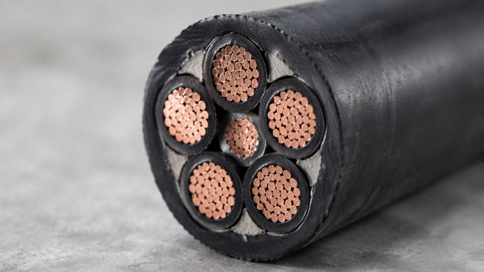
IEC 60228 defines conductor stranding classes. Class 5 (flexible) and Class 6 (extra-flexible) use fine-wire stranding down to roughly 0.1 mm individual wire diameter for larger cross-sections — a dramatic difference from the 0.4–0.5 mm wires in a Class 2 fixed-wiring conductor of the same nominal cross-section. More wires, thinner wires, more evenly distributed bending stress. A 35 mm² Class 6 conductor may contain several hundred individual copper wires. Each wire takes a smaller share of the bending strain per cycle, so fatigue life extends by orders of magnitude compared to a coarse-stranded equivalent.
For reeling drum cables specifically, the core arrangement matters beyond just conductor class. Cores are typically arranged symmetrically around a central axis — often with a textile or elastomer filler — so the cable doesn’t develop a torsional bias as it pays on and off the drum. Get this wrong and the cable corkscrews under tension, accelerating jacket wear and eventually pulling joints apart internally.
Elastomeric Compounds: Matching the Chemistry to the Environment
PVC is out for dynamic applications in anything other than mild office environments. The standard compounds for flexible and trailing cables are natural rubber (NR), EPDM, polychloroprene (CR, widely known as neoprene), and thermoplastic elastomers (TPE).
Natural rubber gives excellent flexibility at low temperatures — useful for outdoor crane systems in northern climates — but has poor oil and ozone resistance. EPDM has better ozone and UV resistance and handles a wider temperature range, roughly −40°C to +120°C depending on formulation. Polychloroprene sits in a practical middle ground: good oil resistance, decent flame retardancy, adequate cold flexibility to around −25°C to −35°C. Underground coal mining cables frequently use CR sheaths because of the combined demands of oil exposure, flame resistance, and the risk of mechanical contact with sharp rock faces. TPE compounds are gaining ground for their consistency in extrusion and recyclability, though in harsh mining environments they remain secondary to the proven elastomers.
Sub-Types and Their Specific Demands
Underground coal mining trailing cables follow IEC 60702 and Chinese standard GB 12972, both of which specify minimum flame-retardant and anti-static properties — a non-negotiable in environments with methane risk. These cables typically carry both power and pilot/control cores in a single construction, with screens on control cores to reject noise from the heavy traction load circuits running alongside.
Festoon cables for overhead crane systems face a different mechanical profile: repeated S-bend cycling in the festoon trolley system rather than torsion. The bending radius at the festoon clips can be quite tight, and cables here are usually tested to millions of flex cycles at rated bend radius rather than just the basic cold-bend qualification.
Cold bend testing to −40°C is a standard qualification requirement for mining-grade flexible cables per IEC and relevant Chinese national standards.True
IEC 60702 and GB 12972 both specify cold bend performance requirements for mining cables; −40°C is a commonly specified test temperature for cables intended for extreme-climate or underground mining applications where low-temperature brittleness is a genuine failure risk.
Factory acceptance testing for flexible and trailing cables should include cold bend tests (typically to −40°C for mining-grade product), flex-cycle endurance testing, conductor resistance verification, spark test on insulation, and sheath adhesion checks. Jinda’s flexible cable production lines incorporate these protocols as standard, with flex-cycle rigs running representative bend-radius and cycle-rate profiles that reflect actual trailing and reeling applications — not just the minimum the standard requires. In practice, a cable that only just passes the standard test may still disappoint in a high-cycle application; the margin between pass and field performance is where manufacturing consistency counts.
If you are specifying a flexible or trailing cable and the supplier can’t tell you the individual wire diameter in the conductor or the specific elastomer compound and its rated temperature range, that’s a problem worth addressing before you’re chasing a fault on a longwall shearer at 2 a.m.
Type 7 — Solar PV, Wind, and EV Charging Cable: Cables Engineered for the Energy Transition
Conventional power cable datasheets were written for buildings and substations. Renewable energy and EV charging infrastructure break most of those assumptions — outdoor DC strings running at voltages that demand safety class II double insulation, nacelle cables that twist through 360° tens of thousands of times over a turbine’s service life, and public-space charging cables that get dragged across wet asphalt by people who couldn’t care less about minimum bend radius. Each of these applications pushed the cable industry to develop genuinely distinct product lines rather than just reclassifying existing inventory.
Solar DC Cable: UV Resistance Is Non-Negotiable
Rooftop and ground-mount PV strings run at DC voltages that have climbed from 600 V to 1,000 V and now 1,500 V systems — with some utility-scale designs pushing to 1,800 V DC. The insulation system has to handle that continuously, in direct sun, over a warranted 25-to-30-year panel life. That’s the engineering brief for IEC 62930 (which superseded the older EN 50618) and the TÜV 2PfG 1169 certification that most serious EPC contractors still require as a procurement condition.
Double insulation — a cross-linked polyethylene (XLPE) inner layer plus a UV-stabilised XLPE or EPR outer sheath — provides safety class II compliance, meaning the cable itself is a shock protection measure even if a connector is accidentally opened under load. Conductors are typically tinned copper rather than bare copper; in high-humidity coastal and agricultural sites, the corrosion protection on tinned strands makes a measurable difference in contact resistance at connectors over a decade of thermal cycling. Temperature range for compliant solar cable runs from −40°C to +90°C continuous, with short-term peak ratings to +120°C — relevant in the summer cable tray temperatures you’ll actually see in the Middle East or southwestern China.
Wind Turbine Cable: The Torsion Problem
Wind cable is a smaller volume category than solar, but technically it’s probably the most demanding of the three. The transition between the fixed tower structure and the rotating nacelle requires a cable that can accept continuous torsion — typically ±180° per rotation, across hundreds of thousands of cycles over a 20-year turbine life. Standard stranding classes won’t survive that. Wind turbine cables use Class 5 or Class 6 fine-wire stranding combined with elastomeric sheaths — usually EPR or a specialist thermoplastic elastomer — that flex without work-hardening.
Offshore installations add low-temperature performance requirements (−50°C for some North Sea and Baltic specifications) and strict flame retardancy per IEC 60332-3-22 for tray runs inside the tower, where a cable fire in a confined steel column is a serious incident. In practice, get the torsion cycle count and the angular range from the OEM before specifying — those numbers vary enough between turbine platforms to matter.
EV Charging Cable: Public Environment, Punishing Use
IEC 62893 covers AC Mode 3 charging (the wall-box standard) through to DC Mode 4 fast charging. The physical construction reflects the abuse these cables take. A typical Mode 3 charging cable carries two or three power conductors, a PE, plus a pilot/control conductor for the communication between vehicle and EVSE. Ultra-fast DC chargers — 150 kW and above — increasingly incorporate a liquid cooling channel running alongside the conductors, which allows smaller conductor cross-sections at high continuous current; that’s why some 350 kW charger cables feel like a garden hose.
The outer sheath is thermoplastic polyurethane (TPU) in virtually every serious commercial product. TPU’s abrasion resistance and UV stability in public charging environments is genuinely better than PVC or standard rubber — the difference shows up after two or three years in a high-traffic car park.
Market Scale and What It Means for Procurement
Roughly 350 GW of solar capacity was added globally in 2023. At typical string cable consumption rates for utility-scale plants, that translates to enormous annual cable demand concentrated in a relatively short procurement cycle — EPC contractors for large solar parks often need full cable packages delivered within a 3-to-6-month window. EV sales exceeded 14 million units in 2023, and public charging infrastructure is running behind that adoption curve, which means charging cable demand is still accelerating rather than plateauing.
Jinda has extended its manufacturing scope to cover IEC 62930-compliant solar DC cable, wind torsion cable, and IEC 62893 EV charging cable as dedicated product lines — not conversions of standard catalogue items — specifically to serve solar EPC contractors, wind turbine OEMs, and the charging network operators who need both technical compliance documentation and the supply volume consistency that comes from a manufacturer operating across five production bases.
Solar DC cables certified to IEC 62930 and TÜV 2PfG 1169 are required to demonstrate UV resistance, double insulation, and rated performance across the −40°C to +90°C temperature range.True
IEC 62930 (incorporating EN 50618) and the TÜV 2PfG 1169 specification both mandate UV resistance testing, safety class II double insulation construction, and thermal performance across this temperature range as baseline certification requirements for photovoltaic cables.
Type 8 — Data, Network, and Fiber Optic Cable: The Nervous System of Digital Infrastructure
Specify the wrong copper category in a structured cabling design and you won’t know it until someone tries to run 10GbE across a 90-meter horizontal run and wonders why the switches keep dropping packets. That’s a real commissioning headache — re-pulling cable through a finished ceiling costs far more than the upgrade would have at procurement stage.
Copper Structured Cabling: Category Differences That Actually Matter
The Category numbers — Cat5e, Cat6, Cat6A, Cat8 — are not just marketing tiers. Each reflects a specific set of physical construction decisions.
Cat5e runs to 100 MHz, supports 1 Gbps at the full 100-meter channel length. The pairs are tightly twisted but there’s no internal separator; the cable stays reasonably slim. Fine for standard office drops and most light industrial sensor networks. Cat6 pushes to 250 MHz and can deliver 10 Gbps, but only up to roughly 55 meters before crosstalk degrades the signal — a constraint that catches out designers who copy-paste the 100-meter rule from Cat5e specs. The physical difference is a plastic spline or cross-web separating the four pairs inside the jacket, which increases the outer diameter noticeably; Panduit and Belden both make this obvious in their catalog drawings.
Cat6A raises the ceiling to 500 MHz and restores the full 100-meter 10G reach, achieved through tighter pair twist rates, individual pair shielding in the F/UTP or S/FTP variants, and a substantially larger diameter — some Cat6A cables run 8–9 mm, which means tighter conduit fill calculations and heavier patch panel depth. Worth it in data centers or dense-switch wiring closets where 10GbE is the baseline expectation.
Cat8 is a different animal: 2000 MHz, up to 40 Gbps, but only at a maximum channel length of 30 meters. It’s a data center top-of-rack solution — server to switch, switch to switch — not a general-purpose horizontal cable. If someone quotes Cat8 for a 60-meter office floor run, that’s a specification error.
Coaxial Cable: Still Working Hard in RF and Surveillance Applications
Coaxial gets dismissed as legacy infrastructure, which is partly fair and partly wrong. In CATV distribution, CCTV systems, and RF antenna feeds, coaxial remains the practical choice because its construction — center conductor, solid or foam polyethylene dielectric, aluminum foil plus copper braid shield, outer jacket — maintains controlled characteristic impedance (typically 50 Ω for RF systems, 75 Ω for video) across long runs without the balanced-pair sensitivity to EMI.
Velocity of propagation matters here more than most engineers remember. A foam PE dielectric pushes VOP to 85% or higher versus roughly 66% for solid PE, which affects signal timing in distributed antenna systems and precise time-delay RF applications.
Fiber Optic: Choosing Single-Mode vs. Multimode Before the BOM Is Locked
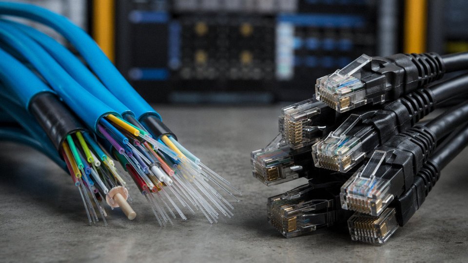
Single-mode fiber (OS1 and OS2, 9/125 µm core) has effectively no distance ceiling at practical network speeds — OS2 ultra-low-loss cable supports 100 Gbps coherent links across tens of kilometers. It belongs in campus backbone runs, inter-building links, and any spine layer where distance or future upgrade headroom is uncertain. Multimode — OM3, OM4, or the newer OM5 wideband variant, all on 50/125 µm core — is optimized for short, high-density runs inside a single building or data hall: OM4 supports 100 Gbps to about 150 meters, OM5 extends that somewhat with shortwave division multiplexing. In a spine-leaf data center architecture, the leaf-to-server links often run multimode for cost reasons, while the spine interconnects warrant single-mode.
The installation discipline differs sharply too. Fiber requires trained splice technicians, proper OTDR testing, and bend radius control — a carelessly routed fiber in a cable tray, kinked by a conduit clamp, will show up as a reflection anomaly that takes hours to locate.
Industrial Fieldbus and Industrial Ethernet Cables
Factory automation environments impose requirements that standard Cat5e or generic coaxial simply won’t meet. PROFIBUS DP specifies a violet-jacketed cable with a specific 150 Ω characteristic impedance and shielded single pair; substitute ordinary data cable and the segment will communicate unreliably or fail altogether at longer runs or higher node counts. PROFINET and EtherCAT use Industrial Ethernet cables with reinforced jackets, increased UV and oil resistance, and often individual pair shielding — Cat5e Industrial variants, rated for continuous flexing in cable carriers, are a real product category distinct from the identical-looking office Cat5e in the adjacent conduit. DeviceNet has its own color-coded flat or round cable with separate power and signal pairs in a defined geometry.
Bend radius is non-negotiable in automation. A fixed-installation industrial Ethernet cable might specify a minimum bend radius of 5× the outer diameter; a moving-carrier (schleppkette) version needs 7.5× or more under continuous flex, and substituting the static version will crack the insulation within a few thousand cycles.
Cat6A structured cabling supports 10 Gbps Ethernet at channel lengths up to 100 meters per TIA-568-C.2-1 and ISO/IEC 11801 standards.True
Both TIA and ISO/IEC specifications for Cat6A (Augmented Category 6) confirm 500 MHz bandwidth and 10GBASE-T operation at the full 100-meter permanent link channel length, distinguishing it from Cat6 which is limited to approximately 55 meters at 10 Gbps.
Jinda’s primary product depth sits in power, control, and armoured cable. That said, on projects combining medium-voltage distribution, industrial control infrastructure, and structured data cabling — a new manufacturing facility, a port terminal, a renewable energy plant — the bill-of-materials spans all these categories simultaneously. Having a supplier that understands the full cable BOM, even for categories they source or partner rather than manufacture directly, cuts the coordination overhead that typically falls on a project’s electrical engineer at the worst possible time.
Type 9 and Type 10 — Submarine Cable and Specialty High-Temperature Cable: Engineering for Extreme Environments
These two categories sit at opposite ends of the application spectrum — one buried under hundreds of meters of seawater spanning continents, the other threaded through a furnace at 180°C — but they share a common trait: standard cable engineering simply doesn’t get you there.
Submarine Power Cable: The Most Complex Cable You Can Specify
If you’ve ever looked at a cross-section drawing of a submarine cable, the first reaction is usually surprise at how many distinct layers are packed into something that still has to coil onto a laying vessel’s turntable without fracturing. The construction starts with the conductor — stranded copper or aluminum — and the insulation system, which is either extruded XLPE for modern HVDC and HVAC designs or mass-impregnated fluid-filled paper for older high-voltage interconnections still operating on grids in Europe and Asia. XLPE has largely displaced fluid-filled designs for new projects, primarily because it eliminates the pressurized oil system and the leak risks that come with it.
The water-blocking system is where submarine cable diverges sharply from land cable. A continuous extruded lead sheath, typically 2–4 mm thick depending on voltage and depth rating, provides the primary moisture barrier. Lead is heavy and expensive, but no polymer jacket alone reliably stops water ingress over a 30- or 40-year service life at seabed pressure. Semiconductor swelling tapes are added at conductor interstices for longitudinal water blocking — if the outer sheath is breached, you want to contain ingress to a short section rather than allow it to migrate along the conductor for kilometers before anyone notices.
Integrated optical fiber units run alongside the power cores in most modern submarine cables, serving real-time distributed temperature sensing and fault location. For a 200 km interconnection cable, knowing within a few hundred meters where a fault or thermal anomaly is located isn’t a luxury — it’s the difference between a targeted repair and replacing a multi-kilometer section.
The armour system on a deep-water cable uses double wire armour in opposing lay directions — this is a torsional balance requirement, not just mechanical protection. A cable lowered from a vessel onto the seabed picks up torsional stress as it pays out; if the armour wires all run the same direction, the cable will try to unwind under its own weight during installation. Bitumen or asphaltic compound fills the interstices between armour wires to suppress corrosion in the inter-wire spaces, where oxygen and chloride would otherwise concentrate.
Application codes vary by segment. Offshore wind array cables operating at 33 kV to 66 kV typically reference CIGRE TB 490 alongside IEC 60502 derivatives. Subsea umbilicals for oil and gas — which bundle hydraulic hoses, chemical injection lines, and electrical conductors in a single structure — are governed by DNV-ST-0359. Cross-strait or inter-island HVDC interconnections at 100 kV to 500 kV bring in a different set of qualification tests entirely, including factory-length electrical testing on reeled sections and mandatory type-approval witnessed by the transmission system operator. These aren’t bureaucratic formalities; a failed joint or insulation void found during factory testing saves years of remediation work on the seabed.
High-Temperature Specialty Cable: Where PVC and XLPE Simply Fail
The failure mode is almost always the same. A maintenance crew uses a standard PVC-insulated control cable near a kiln or process heater, it looks fine on installation, and within six to eighteen months the insulation has embrittled, cracked, and potentially caused an intermittent ground fault that shows up as mysterious process upsets before anyone identifies the cable as the culprit.
High-temperature cable exists specifically to prevent this. Silicone rubber insulation rated to 180°C or 200°C continuous service handles the thermal environment that kills conventional cables. The conductor is typically nickel-plated copper — bare copper begins oxidizing meaningfully above around 150°C, and oxide layer buildup increases contact resistance at terminations over time. Nickel plating suppresses this. For some aerospace and petrochemical applications, pure nickel conductor is used above 250°C, though cost climbs steeply.
The outer protection is usually glass fiber braid, sometimes with a varnish treatment, providing mechanical protection without adding a thermoplastic layer that would itself degrade. In furnace wiring, under-hood automotive harnesses, and aerospace ground support equipment, the cable frequently runs in confined spaces with intermittent contact against metal surfaces — the braid takes that abrasion where a PVC jacket would cut through.
Silicone rubber insulated cables rated to 200°C continuous can remain flexible and electrically intact in environments that cause standard XLPE cable to embrittle within months.True
Silicone rubber retains elasticity at elevated temperatures due to its inorganic Si-O backbone, which has significantly higher thermal stability than the carbon-chain backbone of XLPE or PVC. This is well-documented in IEC 60092-376 and manufacturer qualification testing.
Industrial applications include wiring inside and immediately around tunnel kilns in ceramics manufacturing, petrochemical process heater instrumentation where ambient temperatures routinely exceed 120°C even in cable trays at distance from the source, and automotive under-hood harnesses routed near the exhaust manifold. In each case, specifying standard cable is a short-term cost saving that turns into an unplanned shutdown within a year or two.
Where Jinda’s Capabilities Fit
Jinda’s current product range covers medium-voltage submarine-equivalent cable constructions — lead-sheathed, double-armoured designs suited for nearshore and inter-island applications — alongside high-temperature control cables with silicone insulation for industrial and marine environments. For project-specific requirements at the higher end of submarine cable design, particularly HVDC backbone interconnections or deepwater umbilical configurations, Jinda’s R&D center provides the engineering foundation for configuration development and type testing coordination. It’s worth a direct conversation if your project sits in that territory rather than assuming the answer before asking.
How to Select the Right Cable Type for Your Project: A Structured Decision Framework
Getting the cable type wrong rarely announces itself at purchase order stage. It shows up six months into commissioning as a ground fault in a flooded duct bank, or three years later as premature insulation cracking on a rooftop tray run that nobody thought to specify UV-stabilized sheathing for. The selection framework below won’t replace a qualified electrical engineer on a complex project, but it will stop the most common and expensive mistakes before they reach the procurement stage.
Step 1: Define the Electrical Parameters First
Start with voltage class — not because it’s obvious, but because it’s where specification errors cluster. A 6 kV motor feeder pulled through the same conduit as 1 kV auxiliary circuits is not a shortcut; it’s a code violation and, in practice, a latent failure waiting for the first surge event. Pin down the system voltage (phase-to-phase and phase-to-earth), the continuous current load, whether the supply is AC or DC (this matters acutely for EV charging and solar strings), and the short-circuit rating the cable insulation must survive. Frequency is usually 50 or 60 Hz for power, but variable-speed drives push harmonic content that accelerates PVC aging faster than the nameplate suggests.
Step 2: Map the Installation Environment Honestly
“Indoor” is not a single environment. A clean office riser and a petrochemical pump room are both technically indoors. Run through the real conditions: ambient temperature range (a desert solar farm sees ground temperatures above 50 °C at cable burial depth in summer), moisture or immersion risk, UV and ozone exposure for outdoor runs, presence of corrosive chemicals or hydrocarbons, fire-risk zones requiring LSZH or FR ratings, and whether the route crosses areas where rodents or mechanical impact are credible threats. Each of these drives a sheath or armour choice.
Step 3: Nail Down the Mechanical Duty
Fixed installation in a conduit, direct burial with rocks in the backfill, continuous flexing on a crane pendant, or dynamic loading on a vessel in 3-meter swells — these are categorically different mechanical environments. An armoured cable that performs perfectly in a static trench burial will fail within months on a drag-chain application. State explicitly whether the cable is fixed, occasionally flexed, continuously moving, or subject to torsion. This single distinction separates flexible trailing cable from everything else in the catalog.
Step 4: Identify the Governing Standards Early
This is where international projects get messy. A single wind-farm export cable project may need to satisfy IEC 60502 for the MV collector cables, IEC 60227 or NFC standards for the substation LV work, and a utility-specific specification for the grid interconnect that overrides both. Identify the standards hierarchy before issuing a request for quotation, not during approval submittals. Local utility specs, in particular, frequently add requirements — specific drum lengths, conductor temper, or third-party type-test reports — that a standard catalog product won’t meet without prior confirmation.
Step 5: Validate Supply and Certification Before Committing
A cable that meets the technical spec on paper but arrives without traceable test reports is a liability, not an asset. Confirm that the manufacturer holds current type-test reports from accredited laboratories (KEMA, CESI, CPRI, or equivalent), holds the export certifications relevant to your destination market (CE, SASO, SONCAP, UL listing where required), and can provide factory quality records — conductor resistance test, spark test, and insulation resistance — on the delivery drumset, not just on a generic product family.
Higher upfront cost for XLPE insulation versus PVC, or LSZH sheathing versus standard sheathing, is typically recovered within 3–5 years through longer service life and reduced maintenance costs.True
XLPE MV cables carry a rated service life of 30+ years versus roughly 20 years for PILC or PVC-insulated equivalents under comparable service conditions. The differential purchase premium, typically 15–30% depending on voltage class and conductor size, divided across a service life advantage of 10+ years, produces a straightforward lifecycle cost advantage in most industrial and utility applications. LSZH sheaths eliminate fire-damage liability in occupied buildings, which has measurable insurance and reinstatement cost implications.
Decision Matrix: 10 Cable Types vs. Key Application Factors
| Cable Type | Voltage Class (HV/MV/LV) | Flex Duty | Fire Rating | UV Exposure | Chemical Resistance | Underground Burial | Data Transmission | High Temp (>90 °C) |
|---|---|---|---|---|---|---|---|---|
| LV Power Cable (≤1 kV) | LV | No | Partial | Partial | Partial | Partial | No | Partial |
| MV/HV Power Cable (3.6–500 kV) | MV/HV | No | No | No | Partial | Yes | No | Partial |
| Control & Instrumentation | LV | Partial | Partial | No | Partial | Partial | Partial | No |
| Fire-Resistant / LSZH | LV | No | Yes | No | No | No | No | No |
| Armoured & Underground | LV/MV | No | Partial | Partial | Partial | Yes | No | Partial |
| Flexible & Trailing | LV | Yes | Partial | Partial | Partial | No | No | No |
| Solar PV / Wind / EV Charging | LV/MV (DC) | Partial | No | Yes | Partial | Partial | No | Partial |
| Data / Network / Fiber Optic | Signal | Partial | Partial | Partial | Partial | Partial | Yes | No |
| Submarine Cable | MV/HV | Partial | No | No | Yes | Yes | Partial | No |
| High-Temperature Specialty | LV/MV | Partial | Yes | No | Yes | No | No | Yes |
Yes = primary design intent; Partial = available with appropriate construction option; No = not a design feature of this type
Building a Complete Cable Schedule for Procurement
Vague RFQs generate vague quotes and, eventually, wrong deliveries. A usable cable schedule line item should carry: conductor material and size (mm² or AWG), number of cores, rated voltage (Uo/U in kV), insulation type, screen or armour type, outer sheath material, installation method (direct burial / duct / tray / free air), total length per drum and total project length, and the governing standard with revision number. Add the temperature rating and any special requirements — oil resistance, low-temperature flexibility, halogen-free — as explicit line items, not footnotes.
A template row looks like this: 4-core, 95 mm² copper, XLPE insulated, steel wire armoured, LSZH outer sheath, 0.6/1 kV, direct burial, IEC 60502-1, 1,200 m total, drums of 500 m max.
That level of specificity cuts quote turnaround time and eliminates substitution disputes at delivery.
Working With Jinda on Complex, Multi-Type Projects
Projects that span multiple cable types — a solar-plus-storage facility that needs DC string cables, MV collector cables, control and instrumentation cables, and fiber optic all on a single procurement package — benefit from a supply partner who can resolve the whole schedule rather than fragment it across five vendors with misaligned lead times. Jinda’s technical team, working across five production bases and a track record of delivering to customers in more than 50 countries, is set up for exactly that kind of consolidated project support. Send a cable schedule, even a draft one, and the engineering team will come back with a specification review, not just a price list.
Frequently Asked Questions About Cable Types
What is the difference between a cable and a wire?
A wire is a single conductor — either solid or stranded — with or without basic insulation. A cable is an assembly: two or more insulated conductors bound together, or a single conductor fitted with a multi-layer protective sheath. In practice the boundary gets blurry. Electricians routinely call 2.5 mm² single-core building conductors “wire,” and that’s fine on a domestic job. On a process plant, though, that loose usage causes real specification errors. A 7-core 1.5 mm² control cable with overall screen and PVC outer sheath is not a wire in any useful engineering sense. Keep the distinction clean in your BOQ and purchase orders — especially when working across multiple countries where translation further muddies the terminology.
Can I use the same cable for AC and DC applications?
Not automatically. DC voltage imposes insulation stress differently from AC because there is no zero-crossing to help discharge accumulated charge in the dielectric. A cable rated 600/1000 V AC does not automatically carry a 1000 V DC rating of equivalent safety margin — the DC equivalent is often lower, sometimes significantly so depending on insulation type and manufacturer testing protocol. Solar PV cables rated to IEC 62930 are specifically qualified for DC up to 1.8 kV system voltage, with insulation formulations and ageing tests designed around the DC stress profile. Always check whether the voltage rating on the drum print references AC, DC, or both. Assuming AC-rated cable works on a DC bus is one of those mistakes that tends not to fail immediately — it fails two or three years in, and the root cause takes a while to trace.
What does XLPE stand for, and why is it preferred over PVC for power cables?
XLPE is cross-linked polyethylene. The cross-linking process — whether peroxide, silane, or electron beam — creates a three-dimensional polymer network that does something PVC simply cannot match: it raises the maximum continuous conductor operating temperature from 70°C to 90°C, with a short-circuit emergency rating of 250°C versus 160°C for PVC. That temperature difference translates directly into current-carrying capacity. For a given conductor cross-section, an XLPE cable carries roughly 15–20% more current than a PVC equivalent at the same ambient, depending on installation method and grouping. XLPE also eliminates the plasticizer migration problem that makes old PVC cables crack and harden over time — anyone who has pulled aged PVC cable through a duct knows what that looks like. For MV and HV applications, XLPE’s dielectric strength and low dielectric loss make PVC essentially irrelevant above 3.6 kV.
How do I know if a cable meets international quality standards?
Ask for the third-party type test report, not just the manufacturer’s declaration. Accredited labs — KEMA, DEKRA, BASEC, UL, and regional equivalents — issue reports tied to a specific standard, edition, voltage class, and conductor size. When the report arrives, cross-check three things: the drum label print, the cable’s surface marking, and the test report header all need to reference the same standard edition and same technical parameters. A mismatch on the standard year or voltage class is a red flag worth chasing before the cable reaches site.
Jinda supplies full documentation packages including third-party type test reports, material certifications, and country-specific export compliance documents for all cable categories.True
This is standard practice for export-oriented manufacturers supplying infrastructure and utility projects, where documentation packages are contractual requirements. Jinda's five-site operation and ISO 9001 certification support this capability.
What is the maximum length I can run on a single cable drum?
It depends heavily on cable type and cross-section. LV power cables in smaller sizes — say, 4–25 mm² — commonly come in 500 m to 2,000 m lengths on a single drum. Larger LV cross-sections (185 mm² and above) drop to 500–800 m because drum weight becomes a handling constraint. MV cables are typically supplied in 500 m sections; at 630 mm² 33 kV, a single drum can weigh several tonnes and needs a drum trailer for installation. Jinda can produce non-standard drum lengths for project-specific requirements — this matters for offshore work or long rural feeders where a mid-run joint is genuinely unacceptable. Lead times for non-standard lengths need to be confirmed at order placement, not assumed.
Is armoured cable always required for underground installation?
Not universally, but the cases where unarmoured cable is acceptable underground are narrower than many people assume. Direct burial in unprotected trenches — no conduit, no concrete encasement — requires SWA or AWA armour under virtually every utility and industrial standard. Cables installed in concrete-encased duct banks can sometimes be unarmoured if the duct system is continuous and mechanically sound, but this is subject to the project specification and local utility approval, and in practice most utility engineers push for armour anyway as insurance against future excavation damage. Unarmoured in a duct is a legitimate cost-saving option on a controlled private site; it’s a harder argument to make on a public network.
How does Jinda ensure consistent quality across its five production bases?
A unified quality management system certified to ISO 9001 runs across all five sites, with centralized raw material qualification covering copper rod, XLPE and PVC compounds, and steel wire armour. Process parameters are standardized so that a 95 mm² XLPE LV cable produced at one facility meets the same dimensional and electrical tolerances as the same cable produced at another. Factory acceptance tests — conductor resistance, insulation resistance, high-voltage withstand, and partial discharge testing where applicable — are performed on every production batch before dispatch, not sampled. For customers running large infrastructure projects, Jinda can accommodate third-party witness inspection during FAT, which is increasingly standard on utility and EPC contracts.