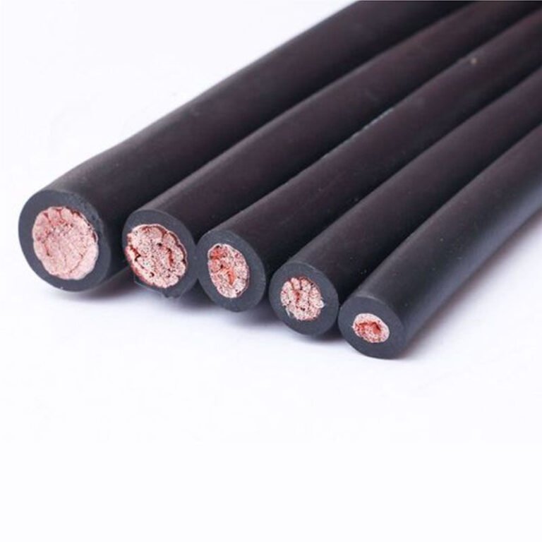
Mislabeling a wire as a cable — or treating a cable like a simple wire in a conduit fill calculation — causes real problems on the floor. Inspectors reject panels. Procurement orders the wrong product. Electricians pull something that won’t bend around a 90-degree elbow without cracking the insulation, and now you’re standing in front of a machine that can’t be commissioned on schedule. The financial drag is rarely catastrophic in a single incident, but across a project with thousands of line items, specification errors compound into weeks of delay and rework costs that nobody budgeted for.
A wire is a single conductor — solid or stranded — used alone to carry current or form part of a larger assembly. A cable is two or more insulated conductors grouped under a common jacket, sheath, or armor. The boundary is crossed the moment individual insulated conductors are bound together as a unified product with an outer covering, regardless of conductor count, voltage class, or whether the conductors are copper or aluminum.
That definition sounds clean, but the real world isn’t. A single-core cable with armor and a PVC oversheath is technically a cable by every IEC and NEC definition, yet procurement teams routinely order it as “single-core wire” — and manufacturers, including the people writing this, sometimes blur the language in catalog copy to match how customers search. Understanding exactly where the line sits, and why it was drawn there by standards bodies rather than by habit, changes how you specify, source, and install anything from a 0.02 mm magnet winding to a 600 mm² feeder.
Conductor Fundamentals: What a Wire Actually Is at the Physics and Materials Level
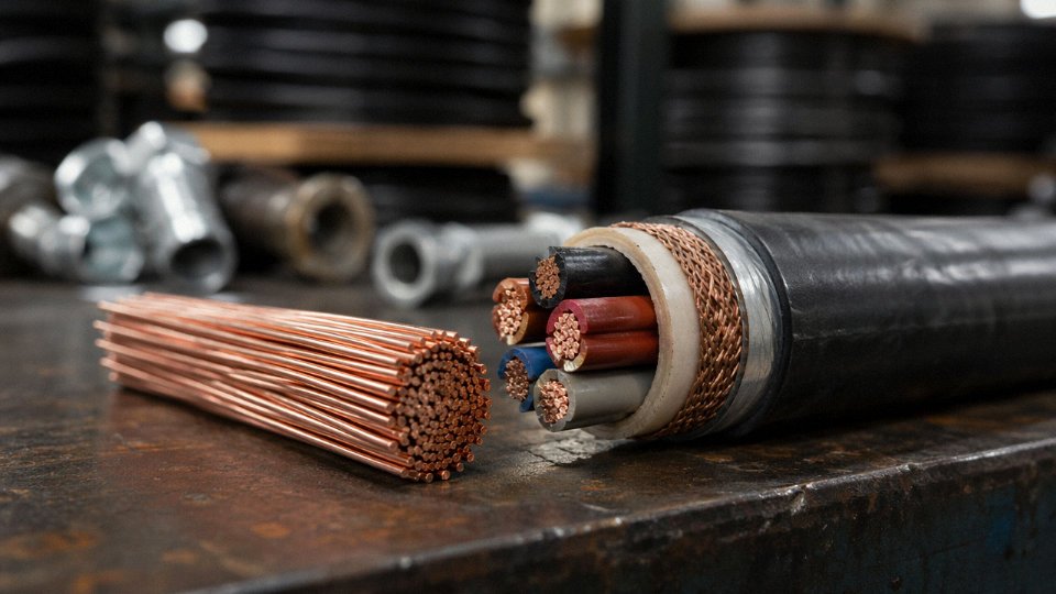
Strip away the marketing language and a wire is defined by three measurable, testable attributes. First: a single, continuous conductor — whether solid or stranded, it presents exactly one electrical path from end to end. Second: a cross-section that is essentially uniform along its length, within the tolerances set by the drawing process (typically ±0.5% on finished diameter for precision wire). Third: an aspect ratio — length divided by diameter — that routinely exceeds 1,000:1 and in practice often runs into the millions. That last point sounds obvious until you realize it’s what physically separates wire from a bus bar, a terminal lug, or a contact pin. Those are conductors too, just not wires.
Conductor Materials and Why the Choice Is Not Arbitrary
Electrolytic tough-pitch copper, ETP or Cu-ETP per EN 13601, sits at roughly 99.9% copper minimum and carries a resistivity of 1.72 × 10⁻⁸ Ω·m at 20 °C. That’s your baseline. Everything else is a trade-off. Aluminum alloy 1350-H19 — the standard for overhead and utility-grade conductors — runs about 61% IACS conductivity, which means you need a cross-section roughly 1.6× larger than copper to carry the same current. That costs you weight savings faster than most procurement specs acknowledge when connector hardware and termination losses are factored in.
Tinned copper is worth calling out separately. The tin coating (usually 1–5 µm, sometimes up to 10 µm for marine-grade) raises contact resistance slightly but pays back in solderability and corrosion resistance in humid or mildly acidic environments. Some automotive harness engineers specify it reflexively regardless of environment — a habit that adds cost without benefit in a sealed, climate-controlled enclosure. Nickel-clad copper is a different animal: used where operating temperatures exceed roughly 200 °C, common in aerospace wiring and high-temperature furnace leads. Resistivity climbs to around 2.4–2.6 × 10⁻⁸ Ω·m depending on cladding thickness, so thermal performance gains have to justify the electrical penalty.
Gauging Systems: A Persistent Source of Procurement Errors
Three systems coexist globally and they are not interchangeable, which causes real specification mistakes on cross-border projects more often than it should. AWG (American Wire Gauge) runs counterintuitively: a higher number means a smaller conductor. AWG 4/0 (read “four-ought”) is 11.68 mm diameter; AWG 30 is 0.255 mm. The IEC system specifies nominal cross-sectional area in mm², which is straightforward — 2.5 mm², 10 mm², 95 mm² — but the “nominal” designation means the actual measured area can sit within a tolerance band, not hit the number exactly. British SWG (Standard Wire Gauge) is largely legacy at this point, but you still encounter it in older UK plant drawings and some Commonwealth-market specifications. Confusing AWG 14 (2.08 mm²) with the IEC 2.5 mm² conductor it roughly resembles is not a catastrophic error in low-power signal work, but in a 20-amp branch circuit it moves you outside the design margin. Inspectors have flagged exactly this kind of substitution during audits of imported panel assemblies.
AWG 14 and IEC 2.5 mm² are electrically equivalent and interchangeable in power wiring.False
AWG 14 has a cross-sectional area of approximately 2.08 mm², about 17% less than IEC 2.5 mm². While often used as rough equivalents for low-power signal wiring, they are not interchangeable in power circuits where current capacity and voltage drop calculations are based on the nominal conductor area specified by the standard.
Wire Drawing: Why Die Tolerances Matter Downstream
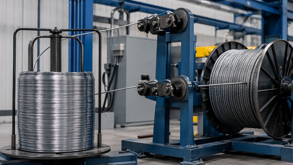
The manufacturing sequence runs: hot rod breakdown from 8 mm ETP rod, then multi-pass cold drawing through a series of tungsten carbide dies, each reducing diameter by roughly 15–25% per pass depending on material and target size. Intermediate annealing cycles — typically at 300–500 °C for copper, duration depending on furnace type and wire gauge — restore ductility that cold work removes. Final spool winding needs to maintain a minimum bend radius or you introduce microcracking at the surface, which only shows up later as premature fatigue failure in flexing applications.
Die tolerance at the final pass is critical and underappreciated. A ±0.002 mm dimensional variation on a 0.5 mm wire represents a 0.4% diameter error — small in isolation, but when you’re stranding 19 or 37 of those wires together, geometric inconsistency creates uneven lay, poor roundness, and voids in the interstices that compromise both the dielectric integrity of any subsequent insulation layer and the overall conductor resistance. Plants that skip regular die inspection — checking for wear-induced bell-mouthing — pay for it in stranding line rejects and inconsistent resistance readings at finished-cable testing.
The Building Wire Threshold
A product like THHN/THWN — a single copper conductor with a PVC or cross-linked polyethylene insulation layer and, in the THWN variant, a nylon jacket — sits right at the boundary of the wire-cable question. It is a wire by conductor definition: one electrical path, uniform cross-section, high aspect ratio. But the presence of a functional insulation system designed to meet UL 83 or equivalent national standards pushes it toward the lower edge of what some standards bodies and most field electricians call a cable. Whether it crosses that line officially depends on which definition you’re working under — and that is exactly the ambiguity the next section addresses.
Anatomy of a Cable: The Structural Layers That Transform Wire into a System
A wire carries current. A cable manages it — mechanically, thermally, electrically, and chemically — across an environment that is almost always trying to destroy it. The difference is architecture.
The Canonical Layer Stack
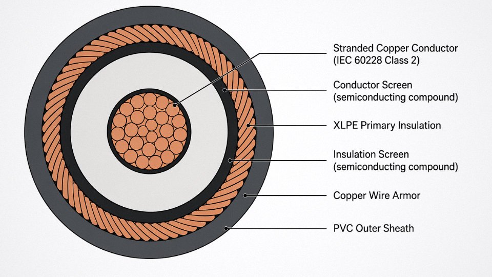
Strip back any medium-voltage power cable and you find the same logic repeated in concentric rings, each one solving a failure mode the layer beneath it creates.
The conductor sits at the center — stranded copper or aluminum, IEC 60228 Class 2 for fixed installation, Class 5 or 6 where flexing is expected. Directly over it, on anything rated above roughly 6 kV, comes a conductor screen: a thin layer of semiconducting compound (resistivity typically in the range of 1–100 Ω·m, depending on the formulation) that smooths the electric field gradient at the conductor surface. Skip this layer and you get partial discharge initiated at strand interstices, which erodes XLPE insulation from the inside out — quietly, over years, until one day the cable fails at 3 a.m. on a production line.
Then comes primary insulation — the layer most people think of as the cable. XLPE dominates medium and high voltage work: continuous rating 90 °C, applicable from 0.6/1 kV distribution cables all the way through 132 kV, 220 kV, and beyond 500 kV transmission grades. PVC is cheaper and still standard for building wire and light industrial cables below 1 kV, but its 70 °C continuous limit matters — run it at 85 °C ambient inside a trunking and you’ve started a slow degradation clock. EPR (ethylene propylene rubber) is the right call in wet or offshore environments where XLPE’s moisture sensitivity is a real procurement consideration, and its flexibility makes it common in trailing cables. PTFE pushes to 260 °C and is genuinely a boundary case: aerospace harness assemblies built from PTFE-insulated conductors are almost universally called “wire” in MIL-spec language, yet a completed harness with a sheath and identifier markings is functionally a cable. Nobody fully agrees, which is part of what makes this question persistent.
Above the insulation, medium- and high-voltage cables add an insulation screen — same semiconducting logic as the conductor screen, but this time controlling the field at the insulation-to-earth boundary. Together the two screens form the contained radial field geometry that makes dry-cured XLPE transmission cable possible.
Why Multiplicity of Conductors Is Not the Defining Criterion
This trips up procurement specs regularly. A twisted pair of bare 0.5 mm² instrumentation wires is two wires, twisted. A single-core 132 kV XLPE cable with semiconducting screens, copper wire armor, and a PE outer sheath is — unambiguously — a cable. The number of conductors is irrelevant to the classification. What matters is the presence of an engineered, multi-functional protective system around the conductor.
A single-conductor high-voltage cable qualifies as a cable even though it contains only one conductorTrue
Cable classification depends on the presence of a multi-layer protective and functional system — including insulation, screening, sheathing, and armor — not on conductor count. IEC and industry practice consistently treat single-core HV cables as cables.
Fillers, Binders, Armor, and What Each Actually Does
Fillers and binders — often overlooked in specs — maintain a round cross-section in multicore cables and prevent longitudinal water migration. Under-spec fillers collapse under crush loads, letting the cores shift and creating impedance variations that throw off differential protection relays. Not a theoretical risk.
Armor is where the mechanical engineering lives. Galvanized steel wire armor (SWA) is the workhorse for direct burial and industrial fixed installs: tensile strength roughly 300–500 N/mm² depending on wire diameter and grade. Aluminum wire armor (AWA) is preferred for single-phase circuits because steel armor on a single-core cable would form a shorted-turn transformer, generating eddy current heating that can run 5–15% additional losses under full load — enough to matter on a large VSD feeder. Steel tape armor (STA) handles crush loads well but offers poor tensile resistance, making it the right choice for duct-routed cables where mechanical impact, not pulling tension, is the threat. Braided armor — typically copper or tinned copper braid — appears on flexible industrial cables and instrumentation types where bending cycles are counted in millions rather than years.
The Outer Sheath: Environmental Barrier and Regulatory Signal
The outer sheath is not cosmetic. In tunnels, rail installations, data centers, and public buildings, halogen-containing PVC sheath produces toxic hydrogen chloride under fire conditions — which is why LSZH (Low Smoke Zero Halogen) compounds are mandated under IEC 60332 and the European EN 50575 Cca/B2ca reaction-to-fire classifications. The difference in smoke density and toxicity between a burning PVC-sheathed cable bundle and an LSZH bundle is substantial enough that several transit authorities specify LSZH even where local code doesn’t yet require it. Standard ST2 PVC sheaths remain appropriate for outdoor industrial and underground applications where fire propagation is less of a concern and UV resistance or oil resistance is the priority.
Sheath color is not arbitrary. IEC 60446 assigns green-and-yellow exclusively to protective earth conductors — using that combination for anything else creates a genuine safety incident waiting to happen during a panel re-wire. Blue designates neutral in AC systems; brown, black, and gray rotate through line conductors in three-phase configurations. On a procurement order, specifying sheath color incorrectly costs a cable return shipment at minimum. At worst, an installer in a hurry follows the color, not the label, and the consequences are obvious.
How IEC, NEC, BS, and UL Standards Formally Define the Boundary Between Wire and Cable
Standards bodies have been wrestling with this boundary for decades, and they still don’t fully agree. That’s not a criticism — it reflects genuinely different engineering traditions, regulatory philosophies, and end-use contexts. What matters practically is that a product classified as a “wire” under one regime may require re-labeling, re-testing, or additional installation hardware when it crosses into a jurisdiction governed by a different standard. Customs disputes, failed inspections, and project delays have all resulted from exactly this ambiguity.
IEC 60050-461: The International Reference Point
The International Electrotechnical Vocabulary defines a cable as “an assembly of one or more conductors and/or optical fibers, with or without armor, forming a composite with a common overall covering.” Parse that carefully. Three structural requirements are embedded: there must be an assembly (implying some deliberate construction combining elements), a composite (the elements are integrated, not simply bundled), and a common overall covering (a unifying outer layer — sheath, jacket, or equivalent). A single insulated conductor with no outer jacket does not meet this definition under IEC 60050-461. It remains a wire, regardless of its cross-sectional area. This is not semantic pedantry; it directly affects how the product must be marked, tested, and certified under IEC-aligned procurement specifications.
NEC Article 100 and the Assembly-Based Approach
The NEC (NFPA 70) takes a different but equally structured approach. It does not offer a single universal definition of “cable” so much as a list of named cable assemblies — AC (armored cable), MC (metal-clad cable), TC (tray cable), USE (underground service entrance cable), and others — each governed by its own article with specific construction requirements covering insulation type, armor, sheath, conductor count, and permitted installation method. Individual conductors pulled through conduit are referred to as “wires” and governed by NEC 310 for ampacity ratings. Once those same conductors are factory-assembled with a common jacket, they become a cable assembly subject to NEC 334, 338, or whichever article covers that specific type.
The practical consequence: a 12 AWG THHN conductor is a wire under NEC 310. That same conductor, factory-assembled with two others under a PVC jacket, becomes NM-B cable under NEC 334. Different installation rules, different inspection checkpoints, different procurement codes. Ordering the wrong classification on a commercial build can require rework that runs into tens of thousands of dollars in labor alone.
BS 7671 and the Single-Conductor Cable
BS 7671 (IET Wiring Regulations, 18th Edition) introduces a definition that trips up engineers familiar only with IEC or NEC: it defines a cable as “a length of single insulated conductor (solid or stranded) or two or more such conductors, each provided with its own insulation, which are laid up together.” Under this definition, a single insulated conductor qualifies as a cable — no outer sheath required, no multi-conductor assembly required. This diverges sharply from IEC 60050-461. In practice it means a product shipped from a continental European facility as a “wire” (no common outer covering, IEC-compliant labeling) may technically be a “cable” the moment it enters a UK project governed by BS 7671. Inspectors working across both regimes routinely encounter this and usually resolve it pragmatically, but procurement documentation should flag it explicitly rather than hoping nobody notices.
A single insulated conductor qualifies as a 'cable' under BS 7671 even without a common outer sheath.True
BS 7671 (IET Wiring Regulations) explicitly defines cable as including 'a length of single insulated conductor,' which diverges from IEC 60050-461's requirement for a common overall covering across an assembly.
UL 44 vs. UL 83: Construction Chemistry, Not Naming
UL draws the wire/cable boundary differently from everyone else — less by structural architecture, more by insulation chemistry and the associated test protocols. UL 44 covers thermoset-insulated wires and cables (cross-linked polyethylene, EPR, silicone rubber). UL 83 covers thermoplastic-insulated wires (PVC, nylon-jacketed THHN/THWN). The same product geometry — a single insulated conductor — appears in both standards. What separates them is not “wire vs. cable” but whether the insulation cures by cross-linking or softens with heat. This matters enormously for procurement: a UL 83 THWN-2 conductor is not interchangeable with a UL 44 RHW-2 conductor in a high-temperature or wet location, even if both are the same gauge and look identical in a photo.
HAR Type Designations: Construction Encoded in the Name
The harmonized cable code used across EU member states encodes the full construction hierarchy directly into the product designation. Take H07RN-F as a worked example: H indicates harmonized (meeting CENELEC requirements across member states); 07 is the rated voltage, 0.7 kV (i.e., 450/750 V); R specifies rubber insulation; N identifies polychloroprene as the outer sheath material; F means flexible stranded conductor (Class 5 per IEC 60228). Every character carries regulatory weight. An H05VV-F designation tells a procurement engineer — without opening a datasheet — that this is a harmonized, 300/500 V, PVC-insulated, PVC-sheathed, flexible cable. Specifying the wrong HAR code on a purchase order is not a minor typo; it can mean receiving a product with a different voltage rating, insulation chemistry, or flexibility class than the application requires.
Cross-Standard Classification at a Glance
| Product Type | Governing Standard | Minimum Construction Requirement | Regulatory Classification |
|---|---|---|---|
| Single bare conductor | IEC 60050-461 | No insulation, no sheath | Wire |
| Single insulated conductor, no outer sheath | IEC 60050-461 / NEC | Insulation only | Wire (IEC/NEC); Cable (BS 7671) |
| Multi-conductor with common jacket | IEC / NEC / BS 7671 | Common outer covering | Cable under all three regimes |
| Named assembly (MC, AC, TC, etc.) | NEC specific articles | Per article construction requirements | Cable assembly |
| Thermoset-insulated single conductor | UL 44 | Cross-linked insulation, specific wall thickness | Listed as wire or cable per UL 44 scope |
| Thermoplastic-insulated single conductor | UL 83 | PVC or nylon insulation, specific wall thickness | Listed wire |
| Flexible harmonized product | HAR / CENELEC | Per HAR code designation | Cable (if sheathed), Wire (if insulated only) |
The takeaway for procurement: always specify the governing standard alongside the product description, not instead of it. “3-core 2.5 mm² flexible cable” means something different on a BS 7671 spec sheet than on an IEC 60227 datasheet than on a UL listing — and the difference can determine whether an installation passes inspection or requires full replacement.
Voltage Rating, Conductor Count, and Shielding: The Three Practical Thresholds Engineers Use
Abstract standards language is useful for resolving disputes on paper. On the plant floor, you need something faster. In practice, most experienced engineers run through three checks — voltage rating, conductor count and lay, and shielding — and those three questions resolve classification correctly about 95% of the time. The edge cases are real, but they’re few.
Voltage Rating: Where the Regulatory Boundary Actually Sits
Below 50 V AC (the SELV ceiling defined in IEC 60449 and echoed in NEC Article 725 for Class 2 circuits), virtually every standard tolerates calling a product “wire.” That’s the world of doorbell wire, thermostat wire, low-voltage lighting leads. Once you cross into 300/500 V rated products — the designation format meaning 300 V conductor-to-ground, 500 V conductor-to-conductor — any product with an extruded outer jacket over multiple insulated conductors is treated as a cable across IEC, BS, and UL frameworks without meaningful exception.
The real friction zone is the 0.6/1 kV boundary. Most industrial classification disputes I’ve seen concentrate here: a single XLPE-insulated conductor on a drum, 1 kV rated, sold as “power cable” by one supplier and “insulated wire” by another. Customs authorities in some jurisdictions apply different tariff codes depending on which term appears on the invoice, and that gap can represent 3–8% in landed cost depending on the trade lane. The 0.6/1 kV designation, per IEC 60502-1, technically applies to multicore power cables, so a single-core version occupies genuinely ambiguous territory in the standard — though almost every competent inspector will call it cable once it carries a bedding layer or outer sheath.
Conductor Count and Lay: The Cabling Process Changes the Product
A single insulated conductor on a reel is a wire. Full stop. The moment two or more insulated conductors are laid up together under a common covering, something structurally different has been created, and that process — cabling — is why it gets the name.
Cabling isn’t just bundling. The conductors are twisted together at a defined lay length (pitch), typically ranging from 8× to 20× the cable diameter depending on application, using either S-twist (left-hand helix) or Z-twist (right-hand helix). This matters operationally: S/Z alternating lay in multi-pair instrumentation cables reduces inter-pair crosstalk measurably. Consistent lay length controls bending radius behavior and affects how the cable distributes tensile load during installation pulls — a cable with tight, uniform lay survives a 5 kN pulling tension through conduit far better than a casually bunched assembly of the same conductors.
Shielding: The Most Definitive Structural Marker
This is the one threshold that removes almost all ambiguity. The instant a product incorporates an overall shield — foil-and-drain, copper braid, or served wire — it has become a cable by construction, even if it wraps only a single signal conductor. Why? Because the shield is not passive packaging. It’s a functional second conductor that must be terminated, referenced to ground, and managed at both ends. That’s a system, not a wire.
In multi-pair instrumentation cables, the distinction between individual pair shielding and overall shielding matters for a different reason. Individual pair shields (each pair with its own foil) control crosstalk between pairs within the same cable. The overall shield handles external interference. High-integrity analog signal cables running alongside VFD power cables in the same tray need both — relying on overall shielding alone in that environment typically produces noise floors 15–25 dB worse than individually shielded pairs, depending on cable separation and tray fill.
Operational warning: Terminating a drain wire at both ends of a shielded cable creates a ground loop. In instrumentation loops carrying 4–20 mA signals, a ground loop induced by even a few millivolts of potential difference can shift readings enough to cause nuisance trips or missed process alarms. Terminate drain wires at one end only — almost always the control panel end — unless your system design explicitly specifies otherwise.
Edge Cases Worth Knowing Cold
Magnet wire (enameled, single conductor, no outer sheath) is wire by every measure — the insulation is a thin varnish film, there’s no jacket, no lay, no system. Coaxial cable sits at the opposite extreme: single inner conductor, but the outer conductor and shield are the same element, and the product is universally called cable in every standard and catalog. Don’t let the “single conductor” argument confuse that classification.
Mineral insulated cable (MICC, sometimes called PYRO after the legacy Pirelli brand name that still shows up on old drawings) is worth flagging. Solid copper conductors embedded in compressed magnesium oxide powder inside a seamless copper tube — unusual construction, but cable by every standard. The MgO performs as both insulation and mechanical fill; the copper tube is simultaneously the outer conductor reference and the armor. Some younger engineers see “solid conductors, no twist, no braid” and hesitate. Don’t. It’s cable.
A Five-Question Classification Sequence
When a product arrives without clear documentation, walk this sequence:
| Question | Yes → | No → |
|---|---|---|
| 1. More than one insulation system present? | Go to Q2 | Likely wire — continue to Q4 |
| 2. Common outer covering over all conductors? | Go to Q3 | Assembly of wires, not a cable |
| 3. Overall or individual shield present? | Cable — confirmed | Go to Q4 |
| 4. Voltage rating ≥ 300/500 V with outer jacket? | Cable | Go to Q5 |
| 5. Listed under a named cable type in NEC Chapter 3 or an IEC 60xxx cable standard? | Cable | Wire |
Five questions, unambiguous exit. In my experience this handles roughly 90% of real field queries without needing to open a standard.
A shielded single-conductor product is classified as a cable under IEC construction criteria, not as a wire, because the shield constitutes a functional second conductor requiring active termination.True
IEC and UL cable standards define cable by the presence of a system of conductors under a common covering; a shield with drain wire satisfies this criterion regardless of how many signal conductors are present, which is why coaxial and single-conductor shielded products appear in cable — not wire — product families across all major standards.
Customs Tariffs, Fire Testing, and Warranty Clauses: Commercial Consequences of Misclassification
Getting the wire-versus-cable distinction wrong on a purchase order or shipping manifest is not a paperwork nuisance. It can trigger retroactive duty assessments, void insurance coverage on an entire installation, or put an EPC contractor in breach of contract before the first load cycle.
HS Code Divergence and the Duty Gap
Bare copper wire — uninsulated, unstranded rod or drawn conductor — classifies under HS Chapter 74 as a semi-finished metal product. Bare aluminum goes into Chapter 76. The moment insulation or sheathing is applied, the product migrates to HS 8544, and from there the subdivisions matter enormously. Insulated wire rated below 80 V lands differently than cable rated 1 kV and above, and the duty treatment under 8544.42 versus 8544.60 can diverge by roughly 3–7 percentage points in the EU, India, and Brazil, depending on the specific bilateral trade agreement in effect at time of import.
That gap compounds fast. On a 20-container project shipment — say, 500 tonnes of 11 kV XLPE power cable — a 5-point duty misclassification can add USD 80,000–200,000 in unanticipated landed cost, depending on declared CIF value and country of import. Customs authorities in Brazil and India have both historically scrutinized cable-versus-wire declarations because the arbitrage incentive is obvious to everyone involved.
Misclassifying a medium-voltage power cable as bare conductor under HS Chapter 74 instead of HS 8544 can reduce declared import duty in some markets, but triggers retroactive assessment plus penalties if discovered during post-clearance audit.True
Customs authorities in the EU, India, and Brazil conduct post-clearance audits and can reassess duty plus apply penalties ranging from 10% to 100% of unpaid duty depending on jurisdiction and whether fraud is presumed.
The Fire Testing Classification Cliff
IEC 60332-1 tests a single wire or cable for vertical flame propagation — a relatively forgiving pass criterion. IEC 60332-3 tests bunched cables in a tray under sustained flame exposure, which is an entirely different physical scenario. A product that comfortably clears the single-specimen test can fail the bunched-cable test because heat accumulates differently when forty cables are touching each other in an installation tray.
The EN 50575 Euroclass system adds another layer. Eca through B2ca ratings apply only to cables installed in buildings. An individual conductor pulled through conduit does not require a Euroclass marking under the Construction Products Regulation — but if an installer substitutes a conduit wire for a rated cable because “it’s basically the same thing,” the Euroclass compliance of the assembly collapses. Building inspectors in Germany, the Netherlands, and increasingly in the UK post-Brexit have started flagging exactly this substitution during commissioning sign-off. The consequence is rip-and-replace, not a waiver.
Ampacity Derating: Where Physics Meets Liability
NEC Table 310.15(B) and IEC 60364-5-52 both apply correction factors to account for how heat dissipates from a conductor depending on installation method, grouping, and ambient temperature. The correction factors for a cable differ from those for a single insulated conductor in conduit because the cable’s outer sheath adds thermal resistance. Using the single-conductor ampacity table for a multi-core cable installation — or vice versa — can produce a 15–30% overcurrent margin error before any additional safety factor is considered. That range depends on conductor cross-section, grouping factor, and ambient temperature, but even the low end is enough to cause insulation degradation over 3–5 years of continuous loading rather than visible immediate failure.
In practice, this tends to surface during an insurance investigation after a thermal event, not during design review.
Warranty Voids and EPC Contract Exposure
Standard contractor all-risk insurance policies and EPC contracts typically reference cable by IEC or UL type designation in the technical specification annex. “IEC 60502-1 cable” and “single insulated conductor per IEC 60227” are not interchangeable under those clauses, regardless of whether both products carry the same conductor cross-section. Substituting one for the other — even with good intentions, perhaps because the specified cable was on a 14-week lead time — voids the connected equipment manufacturer’s warranty on termination hardware and switchgear, and in most EPC contracts constitutes a material technical deviation that opens the contractor to liquidated damages.
Export Documentation and the Fraud Line
Legitimate cable supply comes with a traceable document trail: a third-party test report against the applicable IEC or UL standard, a Declaration of Conformity, and a third-party inspection certificate from an accredited body. Shipping a wire product relabeled as cable to meet local-content thresholds or circumvent import quotas is customs fraud in every major jurisdiction. The paper trail — or its absence — is exactly what customs forensic auditors look for first. A test report dated after the shipment date, or a DoC referencing a standard the product cannot physically meet, is a red flag that has ended supplier relationships and triggered multi-year debarment from public procurement in several markets.
The document requirements are not bureaucratic overhead. They are the only objective evidence that the product you bought is the product the spec demanded.
Application-Specific Classification: Power, Control, Instrumentation, Data, and Bare Conductor Products
The wire-cable boundary does not move at a fixed point — it shifts depending on the application domain. A classification that makes sense for a 500 kV transmission circuit is almost meaningless when you’re specifying a Profibus segment or an overhead distribution span. Here is how each major product family sits in practice.
Power Cables: The Unambiguous Case
From a 1.5 mm² distribution tap up to a 2,500 mm² submarine interconnector, power cables are cables by every definition without exception. The construction demands it: voltage-rated XLPE or EPR insulation (thickness specified per voltage class), a metallic screen to handle capacitive charging current and fault current, armor (SWA or AWA for most land installations, wire or tape armor for submarine), and an outer sheath that doubles as a mechanical and chemical barrier. Products like NYY, N2XY, and XLPE SWA are governed by IEC 60502-1 up to 30 kV and IEC 60502-2 for medium- and high-voltage ranges, with EHV designs above 150 kV following IEC 62067. No single insulated conductor — regardless of cross-section — can substitute here, because the screen and sheath are not optional features. They are load-bearing parts of the dielectric design.
Control Cables: Cable by Core Count
Control cables sit at 0.6/1 kV, typically with individual cores from 0.75 mm² to 6 mm² and core counts ranging from 4 up to 61. That large core count is the real differentiator from a power cable — each core is small, but there are many of them, twisted, filled, and collectively sheathed under IEC 60227 (PVC insulation) or XLPE variants. They wire switching panels, relay logic, motor starter circuits, and solenoid valve banks. An optional collective screen handles EMI in noisier environments. Calling any individual core a “wire” while the bundled, sheathed assembly sits in a cable tray is technically defensible, but commercially and contractually they are always sold and specified as cable. Inspectors checking a control panel against an IEC 61439 schedule will expect cable conformance documentation, not wire test reports.
Instrumentation Cables: Construction Makes Substitution Impossible
Instrumentation cables — individually screened pairs or triples, plus an overall screen, rated typically at 300/500 V — are the clearest case where the physical construction makes single-conductor substitution literally impossible. Each pair carries its own foil shield and drain wire. Strip that away and the signal integrity collapses. ANSI/ISA-5.1 governs signal identification; IEC 60079 layers on additional requirements for hazardous-area installations, including gas and vapor blocking for Zone 1 and Zone 2 — a feature a bare wire can never provide. In my experience, instrumentation cable is also where misspecification causes the most diagnostic pain. Running a standard multi-core control cable into a gas detection loop because “it has enough cores” is a shortcut that tends to surface during commissioning, not during procurement.
Data and Communications Cables: Even a Single Fiber Is a “Cable”
The data industry calls everything a cable, and IEC 60050-461 accommodates this explicitly. Cat 5e, Cat 6, and Cat 6A Ethernet cables derive their classification from multi-pair construction and an overall jacket — typically four pairs, each twisted at slightly different lay lengths to manage crosstalk. Coaxial products like RG-6 and RG-11 are single-conductor at the signal level but layered in construction. Fiber optic assemblies carry this further: an optical fiber is not a conductor at all, yet “fiber optic cable” is universally accepted and IEC-defined. The word “cable” here signals a protected, deployable, system-ready assembly rather than a raw material.
Bare Conductors and Overhead Line: Where the Terminology Gets Genuinely Blurry
ACSR (Aluminum Conductor Steel Reinforced), AAAC, and AAC are wires by strict definition — no insulation, no sheath, no jacket of any kind. IEC 61089 and ASTM B232 govern them independently of the insulated cable standards. Yet utility engineers routinely call them “overhead line conductors” or even “bare cables.” That usage is not sloppy; it reflects the fact that these products are engineered assemblies — multiple aluminum strands helically laid over a steel core, each strand produced to tight tensile and conductivity tolerances. The steel core is doing structural work; the aluminum layers are doing electrical work. Calling the finished ACSR a single “wire” understates its complexity. The honest answer is that bare overhead conductors occupy a gray zone: wire by material and insulation status, something closer to cable by function and multi-element construction.
Optical fiber qualifies as a 'cable' under IEC 60050-461 even though it contains no electrical conductor.True
IEC 60050-461 defines cable around the concept of a protected assembly of one or more transmission elements, explicitly including optical fibers. The definition does not require electrical conductivity.
The takeaway for procurement: matching a product family to the right specification standard is not just terminology hygiene. Power, control, instrumentation, and data each have distinct test regimes, fire-performance requirements, and conformity marks. Ordering the wrong product family — even one that looks physically similar — can mean failed FAT, rejected customs entry, or a voided warranty on the installed system.
Manufacturing Process Differences: How the Factory Floor Reflects the Wire-Cable Distinction
Walk through any integrated cable facility and the distinction between wire and cable stops being abstract almost immediately. The equipment tells the story.
Wire Plant: High-Speed Conductor Production
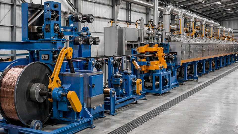
It starts with rod — typically 8 mm copper or aluminum rod coiled from a rod mill or purchased from a rod supplier. Rod breakdown machines, drawing somewhere around 2,500 kW installed power, pull that rod down to intermediate sizes in the 1.2–2.5 mm range through a series of hardened dies. The metal work-hardens as it goes, which is why continuous annealing units sit downstream: steam or electric-resistance furnaces running roughly 200–400 °C (the exact setpoint depends on conductor alloy, temper spec, and target elongation — not a fixed number you can lift from a table). Fine wire drawing machines then take intermediate wire further down, sometimes to 0.05–0.1 mm for winding wire, at exit speeds that can reach 4,000 m/min on modern multi-pass equipment. At those speeds, tension control during spooling is not optional. A few grams of imbalance in take-up tension shows up as a broken spool, a tangled coil, or — worse — a resistance deviation that only surfaces during incoming inspection at the customer’s site.
Output is measured in tonnes of conductor per shift. Wire plant KPIs are throughput, die wear rate, and resistance conformance to IEC 60228. That’s essentially it. The product leaving the wire plant is a conductor, possibly with thin enamel insulation on magnet wire, but structurally it is still one thing.
Cable Plant: Where Layers Accumulate and Complexity Multiplies
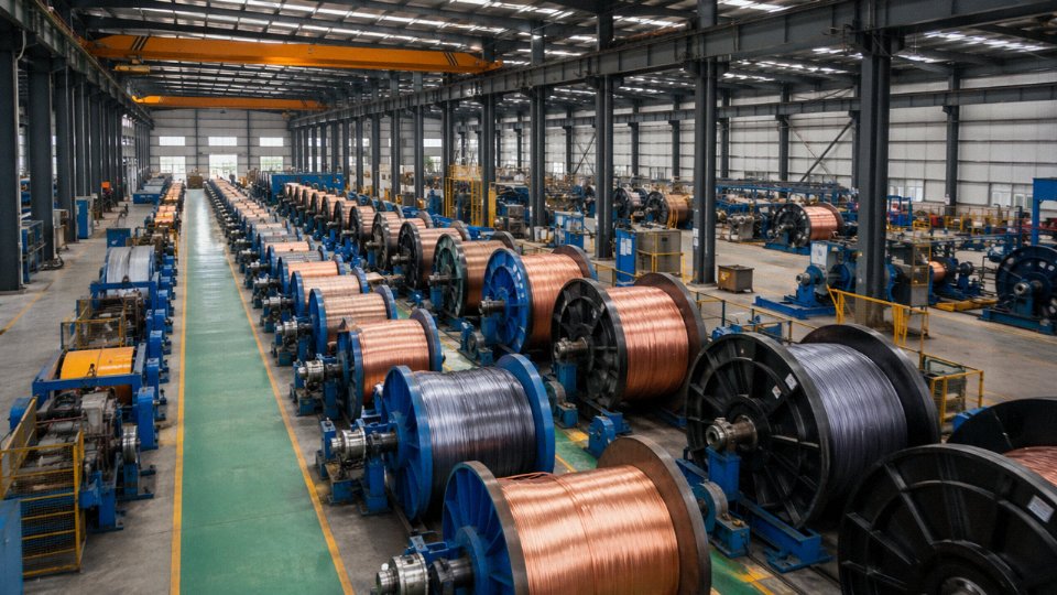
The cable plant receives that conductor — or buys it from the wire plant next door — and begins stacking functions onto it. Planetary stranding machines with up to 91-bobbin capacity twist multiple conductors into a core geometry with controlled lay length. The lay length matters because it directly affects the cable’s flexibility, its electrical balance in multi-core designs, and its resistance to mechanical fatigue in dynamic applications like trailing cables or festoon systems.
Insulation is applied by single-screw tube extruders, typically 90–150 mm screw diameter with L/D ratios around 25:1. PVC insulation runs at 160–220 °C melt temperature; XLPE requires 200–240 °C and then, for cross-linking, passes through a catenary continuous vulcanization (CCV) tube — up to 80 m long on some medium-voltage lines — where high-pressure steam or dry nitrogen cures the peroxide-initiated cross-link reaction. Get the CCV temperature profile wrong by even 10–15 °C and you get incomplete cross-linking, which won’t show up on a spark test but will fail partial discharge measurement and will absolutely shorten service life in field conditions. That’s the kind of thing that causes a transformer feeder to fail at year six instead of year thirty.
After cabling, a sheathing extruder applies the outer jacket. Then it goes to testing.
Where QC Diverges Most Sharply
Wire quality control is comparatively focused: conductor resistance per IEC 60228, tensile strength, elongation at break, and eddy-current surface scanning for surface defects or inclusions. Fast, high-volume, largely automated.
Cable QC is a different operation entirely. Spark testing runs at typically 4–8 kV AC per IEC 60245/60227 protocols on every metre of insulated core before cabling. Finished LV cable drums get an OFC (overvoltage final check) test. MV and HV cables require partial discharge measurement per IEC 60885-3 — equipment that costs more than most wire plants’ entire QC budget. Cold-bend tests, heat-deformation tests, and flame propagation tests are run on the complete assembly, not the conductor alone.
Spark testing at 4–8 kV AC per IEC 60245/60227 is a routine 100% production test applied to every metre of insulated cable core, not a sampling-based check.True
IEC 60245 and IEC 60227 both specify spark testing as a continuous in-line test during insulation extrusion, covering the full drum length, distinguishing it from type or sample tests.
Drum Logistics and Traceability: A Cable-Specific Supply Chain
Wire ships in coils — 100–500 kg typically, manageable by two people with a pallet truck. LV power cable ships on steel or wooden drums ranging from roughly 500 kg to 10 tonnes net. A single 132 kV HV cable drum can run to 1,000 m of product weighing close to 30 tonnes. Drum returns, sea freight blocking and bracing, pulling tension calculations for installation — none of this exists in wire logistics. It’s an entirely different supply chain function, and underestimating it is one of the more consistent mistakes procurement teams make when buying cable internationally for the first time.
Traceability documents reflect this split. Wire manufacturers issue mill certificates referencing IEC 60228: conductor cross-section, DC resistance at 20 °C, material composition, sometimes mechanical properties. Cable manufacturers issue routine test reports drum by drum, referencing the governing standard for the complete product — IEC 60502-1 for LV power cable, for instance — and including results for every applicable routine test. For asset owners working inside an IEC 55000-series asset management framework, that drum-level test report is a primary record. A wire mill certificate, however accurate, does not substitute for it.
Frequently Asked Questions: Wire vs. Cable Definitions, Standards, and Procurement
Is a single-core armored cable still a cable?
Yes, unambiguously. The presence of armor and an outer sheath makes a product a cable under IEC 60050-461 regardless of how many conductors are inside. Single-core steel wire armored (SWA) cables to IEC 60502-1 are routine products — you see them regularly on large MV power circuits, generator output feeders, and transformer tails. Once you get above roughly 300 mm² cross-section, a multi-core construction becomes physically impractical to bend, terminate, and handle on site, so single-core SWA is the standard engineering answer. The single conductor does not demote the product back to “wire.” The armor layer and outer sheath are doing real structural and protective work, which is exactly what the definition is tracking.
A single-core armored product meeting IEC 60502-1 is classified as a cable regardless of conductor count.True
IEC 60050-461 defines cable by its layered construction, not by conductor count. Single-core SWA to IEC 60502-1 explicitly includes armor and outer sheath layers, satisfying the structural definition of cable.
Can I use wire instead of cable in a cable tray installation?
Only if local code explicitly allows it. NEC Article 392.10 does permit individual conductors — wires — in metallic cable trays, but the threshold is 1/0 AWG or larger, and even then the tray must be the right type. Most industrial facilities, and essentially every offshore or marine project, won’t stop there. Insurance underwriters and classification societies (Lloyd’s, DNV, ABS) typically require listed cable assemblies — MC, TC, or the IEC equivalent — because a loose individual conductor offers no mechanical protection and no tested fire performance as a system. In practice, if your project spec says “cable tray installation,” assume cable is required unless you have written confirmation from the AHJ and your insurer. Getting this wrong after installation is expensive.
What is the difference between a cable and a cord?
A cord — more precisely, a flexible cord — is a cable by construction: multi-conductor, insulated, jacketed. The distinction is service duty, not structure. IEC 60227-5 covers PVC-insulated flexible cords; IEC 60245-4 covers rubber-insulated types. The “cord” designation signals that the product is engineered for repeated flexing, pendant use, or connection of portable equipment. It is not intended for fixed wiring inside conduit or a tray. So a power cord on a piece of process equipment is absolutely a cable in structural terms — it just carries additional service-duty ratings that a fixed-wiring cable does not.
Does stranded wire automatically become a cable?
No. Stranding is a conductor manufacturing technique — Classes 2, 5, and 6 under IEC 60228, each with defined strand counts and resistance limits. A stranded conductor with a single layer of insulation and nothing else on top is still a wire. Stranding improves flexibility and resistance to fatigue, but it does not add the sheath, bedding, armor, or screening layers that define cable architecture. The strand count only becomes part of the cable story once those outer functional layers are added.
How does fiber optic cable fit the definition when it contains no electrical conductor?
IEC 60050-461 explicitly covers optical fibers — the definition was never restricted to electrical conductors. Fiber optic products follow the same layered construction logic: fiber or fibers, buffer or loose tube, strength member (usually aramid yarn), outer jacket. IEC 60793 governs the fibers themselves; IEC 60794 governs the cables. For installation, fire rating, and procurement classification, fiber optic cable is treated as cable across every standard system I’m aware of.
What documentation should I require from a supplier to confirm a product is a genuine cable?
A conductor mill certificate alone is not enough — that only tells you about the metal. For a cable, request the routine test report issued against the specific applicable standard (IEC 60502, IEC 60227, IEC 60245, or whichever governs your product), a Declaration of Conformity that references the full cable standard by number and edition, a third-party inspection certificate tied to the actual drum serial numbers on your order, and the full cable type designation decoded against the harmonized code system or the relevant national standard. If a supplier hesitates on the drum-serial-linked inspection certificate, that hesitation is itself information worth acting on.
Specifying Correctly From Day One: A Practical Checklist for Global Cable Procurement
Getting the wire-versus-cable classification right in the technical sections of this article means nothing if your purchase order still says “1.5 mm² cable, black, 500 m.” That kind of vague specification is how projects end up with PVC-insulated building wire on a direct-burial run, or an unshielded control cable in an instrumentation loop that picks up every variable-frequency drive in the vicinity. The checklist below is built around the five decisions that, in practice, determine whether a delivered product will perform, pass inspection, and hold up under warranty.
Step 1 — Lock Down the Electrical Duty First
Write down system voltage as U₀/U (e.g., 0.6/1 kV or 6/10 kV), maximum continuous current at the design ambient, prospective short-circuit current and clearing time, frequency (50 Hz, 60 Hz, or DC — relevant because AC skin effect changes effective resistance at larger cross-sections), and whether the circuit is power, control, instrumentation, or data. Each answer eliminates entire product families. A 4–20 mA instrumentation loop running at 24 V DC has almost nothing in common electrically with a 3.3 kV motor feeder, even if both look like “multi-core cable” in a catalog. Mixing those categories up at specification stage is where substitution problems begin.
Step 2 — Map the Installation Environment in Detail
Indoor versus outdoor is just the start. Direct burial requires a mechanical protection layer and a sheath rated for soil chemistry — alkaline soils eat standard PVC over time. Cable tray in an open petrochemical plant means UV exposure and possibly chemical splash. Arctic installations (down to -40 °C) need cold-bend tested sheaths; a standard PVC sheath becomes brittle and cracks during pulling at those temperatures. Engine rooms and desert solar installations running at +85 to +90 °C ambient need XLPE or EPR insulation — PVC softens and loses its dielectric properties well before that. Each environmental factor maps directly to an IEC construction clause. Skipping this step and letting a supplier “recommend something suitable” is how the wrong product gets onto the drum.
Step 3 — Name the Governing Standard and Cable Type Code
Specify IEC 60502-1 for low-voltage power, IEC 60502-2 for medium voltage, IEC 60227 or IEC 60245 for PVC or rubber-insulated flexible products, IEC 60092 for marine, IEC 60079 for hazardous-area Ex-rated cables, or the relevant UL type designation with file number for North American projects. Put the harmonized designation code — something like “N2XSY 3×95/16 mm² 12/20 kV” — directly in the purchase order line item. That string encodes insulation material, screen type, cross-section, and voltage class simultaneously. Without it, a supplier has room to ship what they have in stock rather than what your installation requires.
Step 4 — Spell Out Every Construction Parameter
Specify conductor cross-section in IEC mm² or AWG (not both, pick one system per project), IEC 60228 conductor class (Class 2 for fixed wiring, Class 5 for flexible connections), armor type if needed (SWA, AWA, STA, or wire braid), sheath material (PVC ST2, LSZH for tunnel or public-space installations, PCP for oil resistance, MDPE for direct burial), and color code scheme — IEC 60446 for international projects, NEC color conventions for U.S. installations.
Specifying only 'cable' without construction details is the single most common source of non-conforming deliveries in international cable procurement.True
Without a harmonized type designation or explicit construction parameters on the purchase order, suppliers have wide latitude to substitute materials (e.g., PVC for LSZH, unarmored for armored) and still argue the order was fulfilled. This is well-documented in import inspection disputes and factory acceptance testing failures across industrial projects.
Step 5 — Require Test Evidence Before You Accept the Drums
For orders above roughly 500 m, or any project subject to formal commissioning requirements, ask for witnessed drum-level testing: insulation resistance, conductor DC resistance, and high-voltage withstand. Check the test values against IEC 60502-1 Table 2 routine test requirements before you sign the delivery acceptance. Type test certificates matter too — confirm they cover the exact construction you ordered, not a similar product from a different run. A certificate for a 95 mm² conductor does not cover a 70 mm² conductor from the same batch.
Jinda’s five production bases cover the full chain from rod breakdown and wire drawing through stranding, insulation, armoring, and finished cable testing — all under one quality system. With export experience across 50-plus countries and in-house R&D teams aligned to IEC, UL, and GB standards, Jinda’s technical support can help decode local installation codes and translate a site specification into a compliant cable designation before the order is placed, not after the drums arrive on site. Correct specification from day one is not extra administrative work. It is the cheapest form of project insurance available.