How Does a Cable Wire Work? The Physics of Sending Power and Signal Through a Conductor
A cable wire is one of those objects that seems simple until you look closely. You plug one end in, current or signal comes out the other end, and the rest happens silently inside the jacket. The underlying mechanics, though, involve a careful balance of materials and geometry that engineers have been refining since the 1800s. Understanding how a cable wire works does more than satisfy curiosity. It explains why one cable is the right choice and another is a fire waiting to happen.
Electrons in Motion
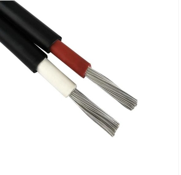
At the most basic level, an electrical cable is a path for electrons to move. The metal inside the cable, almost always copper or aluminum, has free electrons in its outer atomic shells. When you connect the cable to a voltage source, the source pushes those electrons through the conductor. Voltage is the pressure; current is the flow rate; resistance is how much the conductor opposes the flow.
The relationship Ohm taught us in 1827 still holds: voltage equals current multiplied by resistance. A 120-volt outlet pushing a 12-amp load through a circuit sees an effective load resistance of about 10 ohms. The cable itself contributes a small amount of resistance along the way, and that small amount matters more than you might expect. Every ohm of cable resistance becomes a few volts dropped between the source and the load, and a few watts dissipated as heat. Over long runs, those losses can be the difference between an appliance that works correctly and one that hums, dims, or runs hot.
Why Conductor Size Matters
The resistance of a conductor depends on three things: the resistivity of the metal (a fixed property), the length of the conductor (longer means more resistance), and the cross-sectional area (larger means less). Doubling the conductor area cuts the resistance in half. That is why cable sizes are described in terms of cross-section: AWG in North America, square millimeters elsewhere.
A 14 AWG copper conductor has a resistance of about 2.5 ohms per thousand feet. Run that wire across a 100-foot circuit (200 feet round-trip) carrying 15 amps and you drop about 7.5 volts, which is just under the 5% rule electricians use to size circuits. Step up to 12 AWG and the resistance drops to about 1.6 ohms per thousand feet, cutting the voltage drop by almost half. This is the physical reason 14 AWG is rated for 15-amp circuits and 12 AWG for 20-amp circuits in residential installations.
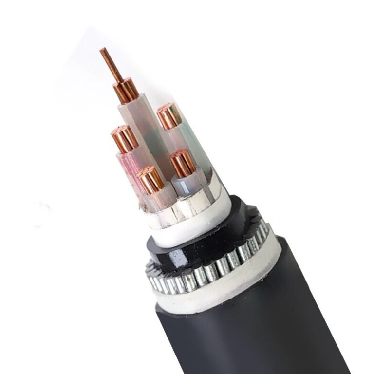
What the Insulation Actually Does
The insulation around each conductor does two jobs at once. The first is preventing current from leaking sideways into anything it should not energize: another conductor, the cable jacket, your hand, a metal stud. The second is withstanding the voltage stress without breaking down. Insulation materials have a dielectric strength measured in volts per mil (thousandth of an inch) or kilovolts per millimeter. Common building wire insulations like PVC and XLPE handle thousands of volts per millimeter, which is why a thin coating can safely contain 120 or 240 volts.
When insulation fails, it fails in one of two ways. It can puncture, allowing current to arc through a now-conductive path, which causes the dramatic short circuits that trip breakers. Or it can degrade slowly from heat, sunlight, chemicals, or age, gradually losing dielectric strength until a fault develops. The cable’s temperature rating, printed on the jacket, tells you how hot the insulation can get without degrading. Exceed it and the insulation life shortens dramatically.
How Power Cables Transport Energy
When you plug an appliance into a wall outlet, you complete a circuit that runs from the hot terminal through the appliance and back through the neutral terminal. The cable inside the wall is just the conduit for this current loop. Alternating current cycles back and forth 60 times per second in North America (50 times in much of the rest of the world), but the electrons themselves only move a tiny distance each cycle. What actually travels along the cable is the electromagnetic field that drives those electrons, propagating near the speed of light through the conductor.
This is why turning on a switch causes a light to come on essentially instantly even though the individual electrons inside the wire are barely shuffling. The field arrives at the load almost immediately and the electrons already present in the load’s filament or coil respond to it.
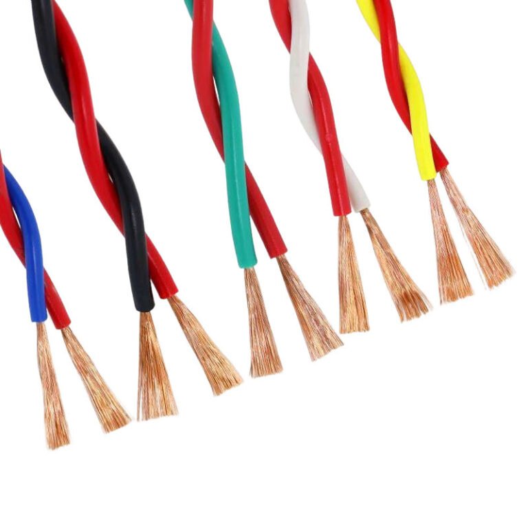
How Signal Cables Carry Information
Signal cables operate on the same physical principles but at much lower voltages and much higher frequencies. Instead of pushing current to do work, they impose a precisely controlled voltage pattern that represents information. Ethernet uses pulse-amplitude modulation across four twisted pairs. HDMI uses transition-minimized differential signaling on three or four data lanes. USB shuffles serial bits at gigabit rates across differential pairs.
The challenge at high frequencies is keeping the signal clean. Two effects work against you. The first is electromagnetic interference: outside fields, radio waves, motors, and other cables all inject noise into the conductor. The second is signal reflection: any change in cable geometry, splice, or termination causes part of the signal to bounce back, blurring the next pulse arriving behind it.
Cable designers fight these effects with three tools. Twisting paired conductors cancels common-mode interference. Shielding (foil, braid, or both) blocks external fields. Controlled impedance, achieved by carefully sizing the conductors and dielectric, prevents reflections by matching the cable’s electrical character to the source and load. Coaxial cable, with its centered conductor inside a continuous shield, takes all three tools to their extreme; that is why it is the preferred carrier for the highest-frequency analog signals.
How Fiber Optic Cables Differ
Fiber optic cables work on a completely different principle: light instead of electricity. A laser or LED at one end of the fiber flashes pulses of light at the appropriate wavelength. The light enters the glass core, where it bounces along by total internal reflection, contained by a slightly less dense cladding layer. At the far end, a photodetector converts the light pulses back into electrical signals.
Because light is unaffected by electromagnetic interference, fiber can operate in environments where copper would be hopeless. Because the glass has very low loss at the right wavelengths, signals can travel kilometers without amplification. And because the modulation speed of modern lasers can exceed tens of gigahertz, fiber can carry vastly more data than copper of any size.
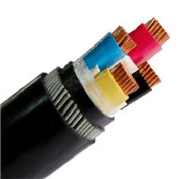
Why the Jacket Matters
The outer jacket is the cable’s interface with the world. It protects the conductors and insulation from moisture, abrasion, sunlight, oil, chemicals, rodents, and mechanical abuse. It also provides the printed surface where the cable’s specifications are listed. In a fire, the jacket material determines how much smoke is produced and whether it propagates flame to the next cable in the bundle, which is why specialty jackets like low-smoke zero-halogen and plenum-rated compounds exist.
A cable without a jacket is just a bundle of insulated conductors. A cable with the wrong jacket for its environment will fail prematurely. Matching the jacket to the application is as important as matching the conductor size to the current.
Putting It All Together
A cable wire works because the conductor moves electrons (or photons), the insulation contains the energy, the geometry shapes the signal, and the jacket survives the world outside. Each layer does a job that the others cannot. Together they form a product that can carry watts or terabits from one point to another with predictable, repeatable behavior. That predictability is what makes modern electrical and electronic systems possible. Take away the cable and everything else stops.