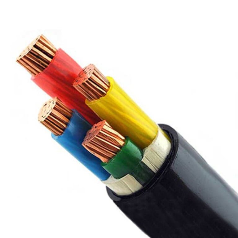
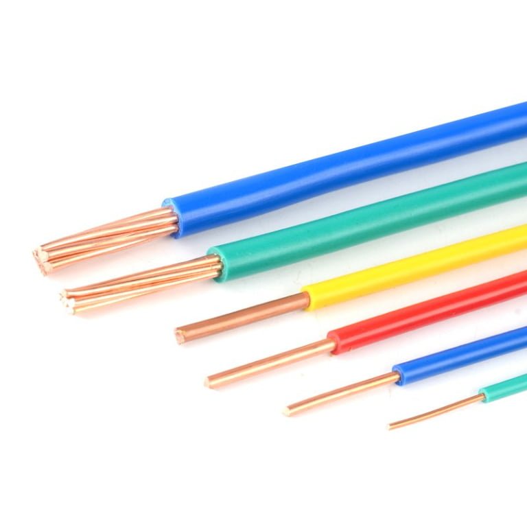
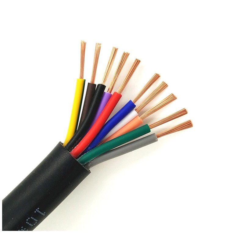
Grab the wrong wire gauge off the shelf — or spec it wrong on a BOM — and you’re not just looking at a rework headache. Run 20 AWG where a 12 AWG circuit is required and you’ve got insulation that softens, a breaker that may never trip fast enough, and in a worst case, a fire starting inside a conduit where nobody sees it for hours. On the cost side, the opposite mistake (over-specifying 12 AWG everywhere “just to be safe”) burns through copper budget and adds weight and bend-radius problems in tight enclosures. Getting the gauge right matters before the wire gets pulled, not after.
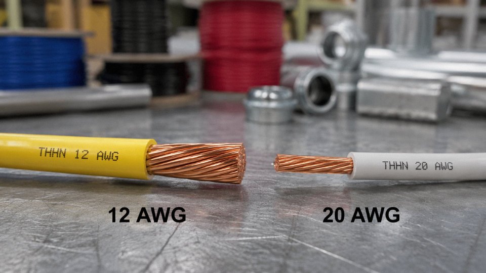
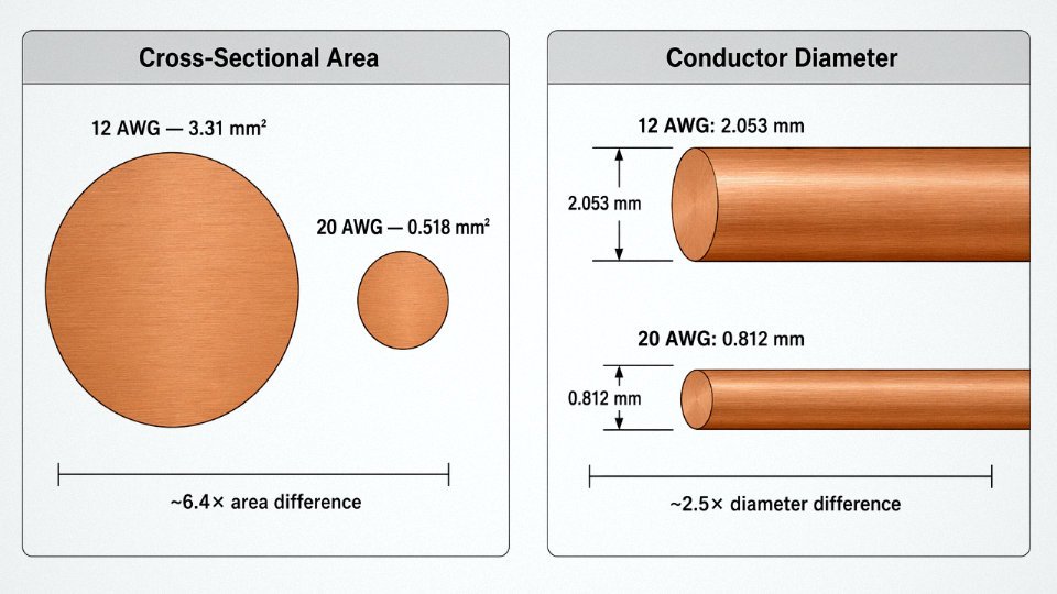
12 AWG wire is significantly thicker than 20 AWG. A 12 AWG copper conductor measures 2.053 mm in diameter with a 3.31 mm² cross-section; 20 AWG measures 0.812 mm in diameter with only 0.518 mm². That makes 12 AWG roughly 2.5 times thicker in diameter and about 6.4 times larger in cross-sectional area — a size difference that directly drives ampacity, voltage drop, and safe circuit design.
What trips up experienced engineers almost as often as beginners is that AWG runs backward: the higher the gauge number, the thinner the wire. It’s counterintuitive enough that even seasoned procurement managers occasionally double-check it. That inverted numbering also means the performance gap between 12 and 20 gauge isn’t just physical — it cascades into resistance, heat generation, breaker sizing, and application suitability in ways worth understanding in detail.
AWG Numbering Logic: Why a Lower Number Means a Thicker Wire
The inverse relationship trips up engineers and procurement managers alike, especially those more familiar with IEC metric sizing. Here’s what’s actually happening mathematically.
AWG — American Wire Gauge — was standardized around a geometric series, not an arbitrary sequence. The system was built backward from two fixed endpoints: 0000 AWG (4/0) at the large end and 36 AWG at the fine end. Between those endpoints, 39 steps divide the diameter by a precise ratio at each step. That ratio works out such that every 6 gauge steps, the diameter changes by approximately a factor of 2. Every 3 gauge steps, the cross-sectional area changes by roughly a factor of 2. This isn’t a coincidence or a rounding convenience — it’s baked into the underlying formula.
The exact formula for conductor diameter in inches:
diameter (in) = 0.005 × 92^((36 − AWG) / 39)
Plug in AWG 12: 0.005 × 92^(24/39) ≈ 0.0808 inches (2.053 mm). Plug in AWG 20: 0.005 × 92^(16/39) ≈ 0.0320 inches (0.812 mm). The exponent shrinks as the gauge number rises, which is exactly why a higher number produces a smaller wire. You’re moving down the geometric series toward the fine end. Once you see that, the “backwards” logic stops feeling backwards.
The AWG-to-Metric Translation Problem
Outside North America, most engineers specify wire by cross-sectional area in mm² — the IEC/metric convention. A 4 mm² conductor is a 4 mm² conductor. No formula, no inversion, no ambiguity. That directness makes cross-border procurement conversations much cleaner, and honestly, it’s just a more intuitive system for design work.
The table below maps the gauge numbers you’ll encounter most often in control panels, branch circuits, and light industrial wiring against their metric equivalents. The IEC “nearest equivalent” column is exactly that — nearest. Real conductor dimensions won’t always match exactly, so verify cross-section and ampacity independently whenever substituting.
| AWG | Diameter (mm) | Cross-Section (mm²) | Nearest IEC Metric Equivalent |
|---|---|---|---|
| 10 | 2.588 | 5.26 | 6 mm² |
| 12 | 2.053 | 3.31 | 4 mm² |
| 14 | 1.628 | 2.08 | 2.5 mm² |
| 16 | 1.291 | 1.31 | 1.5 mm² |
| 18 | 1.024 | 0.823 | 1.0 mm² |
| 20 | 0.812 | 0.518 | 0.5 mm² |
When sourcing internationally — say, ordering from a manufacturer shipping out of China into a North American project — always confirm which standard the datasheet is written to. A cable listed as “4 mm²” and one listed as “12 AWG” are close but not identical, and in a UL-listed installation that gap can matter.
Solid vs. Stranded: Same AWG, Different Reality
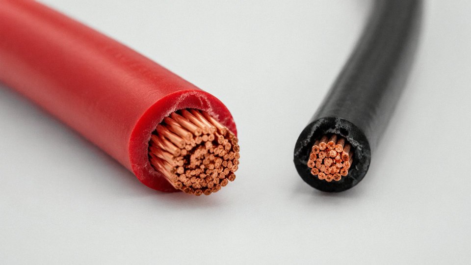
Here’s something that bites people on the procurement side regularly. The AWG number specifies the total conductive cross-section — it says nothing definitive about the outer diameter. A solid 12 AWG conductor is a single 2.053 mm wire. A stranded 12 AWG might be 7 strands of roughly 0.68 mm each, and the assembled bundle will be measurably larger in overall diameter once you account for the gaps between strands and the jacket that goes over them. On a 12 AWG solid conductor, the bare wire outside diameter is around 2.05 mm. On a 7-strand 12 AWG, the assembled conductor OD is typically closer to 2.3–2.4 mm, and the finished cable will be correspondingly bulkier through conduit fill calculations.
This matters when you’re specifying conduit fill, selecting compression lugs, or ordering pre-terminated assemblies. Specify stranding explicitly — “12 AWG, 7-strand, Class B” rather than just “12 AWG” — or you’ll get whatever the supplier’s standard product happens to be.
Two Misconceptions Worth Killing Directly
Higher AWG numbers indicate better quality wireFalse
AWG numbers describe conductor diameter only, derived from a geometric series. A higher gauge number means a thinner conductor. Quality is determined by conductor purity, insulation grade, stranding class, and manufacturing tolerances — none of which are encoded in the gauge number.
The other one comes up in purchasing: “gauge” and “gage” are the same word, different spellings. Some older industrial catalogs and a handful of regional suppliers still use “gage.” They’re not different product lines or standards. Confusing them won’t cause a procurement error on its own, but it does occasionally generate unnecessary back-and-forth with suppliers who use the older spelling in their part numbering.
Physical and Electrical Property Differences Between 12 AWG and 20 AWG Conductors
Diameter and Cross-Sectional Area
The numbers here are not close. 12 AWG copper measures 2.053 mm in diameter (roughly 0.081 inches) with a cross-sectional area of 3.31 mm². 20 AWG comes in at 0.812 mm diameter (about 0.032 inches) and just 0.518 mm². That’s a 2.5× difference in diameter and roughly 6.4× difference in cross-sectional area — which is why substituting one for the other is never a judgment call you make informally on the floor.
For international procurement specs, always state both the AWG designation and the metric cross-section. A purchasing team in Europe or Southeast Asia may quote you back 0.5 mm² when you wrote “20 AWG,” and 0.5 mm² is close enough that it’s usually acceptable — but 2.5 mm² versus 3.31 mm² for 12 AWG is a real discrepancy worth flagging in the purchase order. Small mismatches in cross-section compound over a long cable run.
DC Resistance and What It Costs You at the Circuit Level
12 AWG copper runs approximately 5.21 Ω/km; 20 AWG is around 33.31 Ω/km. That 6.4× resistance ratio is not academic. In a 24 V DC control circuit with a 30-meter cable run, the voltage drop difference between these two conductors at even modest current is substantial enough to cause relay dropout, sensor misread, or actuator sluggishness — the kind of fault that looks intermittent and takes a technician half a shift to track down.
Low-voltage DC systems are where this bites hardest. At 120 V AC, a few tenths of a volt drop barely matters. At 12 V or 24 V DC, a 1–2 V drop across a long 20 AWG run is 4–8% of your supply rail. That’s before you account for connector resistance and terminal aging.
20 AWG copper has approximately 6.4× higher DC resistance per kilometer than 12 AWG copperTrue
Based on standard resistivity values: 12 AWG ≈ 5.21 Ω/km, 20 AWG ≈ 33.31 Ω/km, ratio ≈ 6.39×. This follows directly from the inverse-square relationship between conductor cross-section and resistance.
Ampacity: NEC Ratings Across Insulation Classes
Under NEC 60°C insulation ratings, copper 12 AWG carries roughly 20 A continuous; 20 AWG is rated around 5 A. That’s a 4:1 ratio, and it’s the figure that governs your overcurrent protection sizing.
Bump to 75°C-rated insulation (common in THHN and many industrial cables) and 12 AWG steps up to approximately 25 A, while 20 AWG moves to around 5–7 A depending on installation conditions. At 90°C, 12 AWG can reach 30 A in free air. These ratings drop significantly in conduit — figure 80% derating as a working assumption when you have three or more current-carrying conductors bundled, and adjust further for ambient temperatures above 30°C.
Aluminum conductors? Upsize by one AWG step as a baseline. 12 AWG aluminum does not equal 12 AWG copper in ampacity; treat it closer to 14 AWG copper behavior. This is a common procurement trap when sourcing wire internationally where aluminum-conductor products may be labeled with the same AWG number without flagging the conductor material prominently.
Weight Per Meter and Its Practical Consequences
12 AWG copper weighs approximately 29.4 g/m. 20 AWG is around 4.6 g/m — roughly one-sixth the weight. Over a 100-meter harness, that’s nearly 2.5 kg difference per conductor. In a robotics arm or an aerospace wiring harness where every gram has a structural and dynamic cost, this matters enormously. Routing 12 AWG where 20 AWG is sufficient adds unnecessary strain on cable supports, increases inertia on moving joints, and complicates the mechanical design of the harness itself.
For fixed industrial installations — motor feeders, panel wiring, equipment interconnects — the weight difference is rarely a deciding factor. But in portable equipment, UAV systems, or anything with repeated mechanical movement, the lighter conductor wins if the electrical parameters allow it.
Flexibility and Routing
20 AWG is noticeably more flexible, especially in stranded form (19 or more strands). It routes through tight bends without fatigue issues and handles repeated flexing cycles well — which is why it dominates in instrumentation loops, thermocouple extension wire, and control signal wiring. 12 AWG, particularly solid, is stiff. It resists bending and springs back, which makes it awkward in tight panel layouts. Stranded 12 AWG is better, but it still requires larger bend radius allowances and takes up more conduit fill area. NEC conduit fill calculations feel abstract until you’re trying to pull a six-conductor 12 AWG run through a conduit that was spec’d for four.
High-Frequency Behavior
At 50 or 60 Hz, both gauges perform essentially identically from a skin-effect standpoint — the skin depth in copper at those frequencies is well above 8 mm, so the entire conductor cross-section carries current in both cases. Above roughly 1 MHz, skin depth drops into the range where conductor geometry starts to matter. The smaller diameter of 20 AWG actually results in proportionally less skin-effect loss per unit cross-section at those frequencies, which is why RF signal wiring and high-speed data lines frequently use fine-gauge stranded or solid conductors rather than heavier wire. For power wiring at industrial frequencies, this is irrelevant. For anyone routing analog sensor signals alongside power in the same tray, it’s a useful reminder that heavier wire is not always better wire.
Correct Application Matching: Where 12 AWG Is Required and Where 20 AWG Belongs
Getting the gauge right isn’t just a code-compliance exercise — it’s the difference between a circuit that runs for decades and one that becomes a smoldering junction box on a Tuesday morning. The two gauges serve almost entirely separate worlds, and the trouble usually starts when someone treats them as interchangeable.
Where 12 AWG Belongs
The most common home for 12 AWG is the standard 20 A branch circuit: kitchen countertop outlets, bathroom circuits, HVAC disconnect feeds, and dedicated appliance circuits all fall under NEC Article 210 and demand nothing thinner. A kitchen that runs a microwave, a toaster oven, and a coffee maker simultaneously will regularly pull 15–18 A in bursts — 14 AWG would be code-legal on a 15 A circuit but leaves almost no headroom, and a lot of residential remodels quietly swap in 20 A breakers without upgrading the wire. That’s a fire waiting to happen.
For 240 V appliance feeds — electric dryers, ranges, window AC units — 12 AWG covers loads up to roughly 20 A at that voltage, though anything above that steps up to 10 AWG or heavier.
Solar PV applications are worth calling out specifically. String wiring from roof-mounted panels down to the combiner box is a frequent use case for 12 AWG USE-2 or PV-rated cable. The continuous DC current from a string of panels in full sun can sit near 80% of the cable’s rated capacity for hours, which is the worst-case thermal scenario for any conductor. Undersizing here degrades efficiency and shortens insulation life faster than most installers realize.
EV charging at Level 1 (120 V, up to 16 A) or Level 2 (240 V, 16–20 A) also lands squarely in 12 AWG territory. The circuit runs at or near full load for hours at a stretch — unlike a table saw that cycles — so you’re essentially stress-testing the wire continuously.
Inside industrial control panels, 12–14 AWG handles power distribution: feeds to motor starters, main breaker inputs, 480 V bus runs. These are high-consequence conductors and should never be undersized to save panel space.
Where 20 AWG Belongs
Twenty-gauge wire has no business carrying serious power, but it’s the right tool for almost everything in the signal and low-voltage world. Thermostat wiring (the classic 18–22 AWG range), security sensor loops, intercom lines, fire alarm initiating circuits — all of these run at 24 V DC or lower with currents well under 1 A. Twenty AWG handles them comfortably and is physically easier to route through conduit or cable trays without bulk.
In automation panels, PLC I/O signal cables are almost universally 20–22 AWG. The 24 V DC control signals running from a proximity sensor to a digital input card carry maybe 10–50 mA. Heavier wire here would just waste money and crowd the terminal blocks.
Consumer electronics harnesses and automotive instrument panels use 20 AWG for LED strips, relay coils, and sensor feeds — applications where flexibility and small bend radius matter more than current capacity.
Voltage Drop: A Worked Comparison
Using V_drop = 2 × L × I × R/1000 (round-trip, copper):
30 m of 12 AWG at 20 A (120 V AC):
V_drop = 2 × 30 × 20 × 5.21 / 1000 = 6.25 V, or about 5.2% — right at the NEC-recommended 5% limit. Acceptable, barely.
30 m of 20 AWG at 3 A (24 V DC):
V_drop = 2 × 30 × 3 × 33.31 / 1000 = 5.99 V, or roughly 25% of the supply voltage — that’s borderline unacceptable for a 24 V control circuit and would cause relay dropouts or sensor errors depending on the device. For genuinely long signal runs, 18 AWG or a step up to 16 AWG is the practical answer.
Now flip it: 20 AWG carrying 20 A would see catastrophic resistive heating — the wire would exceed 200°C within seconds, destroying insulation and likely igniting surrounding material.
Replacing 20 AWG signal wire with 12 AWG in a low-voltage thermostat circuit improves performance.False
Wire gauge does not improve signal quality in a low-current thermostat circuit. Using 12 AWG adds unnecessary bulk, complicates termination at small terminals, and provides no electrical benefit. The correct size for thermostat wiring is 18–22 AWG.
Mixed-Gauge Splicing: A Real Hazard
Never splice 20 AWG into a circuit protected by a 20 A breaker. The thin conductor becomes the weakest thermal link in the circuit, but the breaker won’t see an overload fast enough to protect it — the insulation will fail first. NEC 240.21 governs tap conductor rules carefully: any tap conductor must be sized for the load it serves, with overcurrent protection at the tap point unless specific length and enclosure conditions are met. In practice, if you’re tempted to run a short pigtail of light wire off a heavy-gauge home-run, you need a separate breaker sized for that wire, not just an assumption the upstream breaker will save you.
Outdoor and Wet-Location Considerations
Outdoor use sharpens the stakes. Twelve AWG in direct burial needs USE-2 or at minimum THWN-2 in conduit — the insulation rating matters as much as the conductor size. Twenty AWG outdoors is generally acceptable only for low-voltage landscape lighting or control circuits that carry their own dedicated overcurrent protection, typically a Class 2 transformer. Moisture ingress into a lightly insulated 20 AWG splice can cause resistive heating at levels the upstream protection will never detect. Weatherproof connectors and proper burial depth aren’t optional in these runs.
The two gauges coexist routinely in industrial automation — 12 AWG power feeds and 20 AWG signal cables sharing the same enclosure, routed in separate trays, each doing its specific job. The discipline is keeping them strictly separated, both physically and in terms of overcurrent protection.
International Standards Governing 12 AWG and 20 AWG Equivalents: NEC, IEC, BS, and AS/NZS
AWG is a North American convention. The moment a project crosses a border — or a procurement team sources cable from a manufacturer in China, Europe, or Southeast Asia — the sizing system changes, and assuming a direct substitution without verification is one of the more reliable ways to create an expensive compliance problem on-site.
NEC (NFPA 70) Framework
Under NEC 2023, AWG is the native conductor sizing language. Article 210.19(A)(1) establishes 12 AWG copper as the minimum conductor size for a 20 A branch circuit — this isn’t a recommendation, it’s a code floor. Drop to 14 AWG on that same circuit and you’re looking at a failed inspection and a potential fire hazard if the breaker ever actually carries its rated load for an extended period.
20 AWG occupies a different regulatory space entirely. Article 725.49 permits it for Class 2 and Class 3 remote-control, signaling, and power-limited circuits, where the combination of current-limiting power supplies and low fault energy puts the safety calculus in a different category than a standard branch circuit. Don’t try to extend that permission outside its defined scope — it applies to the circuit classification, not to the wire in isolation.
IEC 60228 and the mm² System
IEC 60228 doesn’t use gauge numbers at all. Conductors are specified by nominal cross-sectional area in mm², and the standard defines Class 1 (solid) and Class 2 (stranded) constructions with specific resistance limits per conductor size. The nearest IEC equivalent to 12 AWG is 4 mm² (actual cross-section 3.31 mm² vs. the 4 mm² nominal), and 20 AWG maps loosely to 0.5 mm² (actual 0.518 mm²).
Loosely is the operative word. Dimensional tolerances, stranding configurations, and resistance limits in IEC 60228 don’t align perfectly with their AWG counterparts. A cable stamped “4 mm²” and one stamped “12 AWG” will perform similarly in most applications, but if your compliance documentation or type-test certificate specifies one system and the installed cable is certified under the other, an inspector or an insurance adjuster can — and sometimes does — treat that as a nonconformance.
4 mm² IEC cable is a direct, interchangeable replacement for 12 AWG NEC cable in any applicationFalse
While 4 mm² and 12 AWG are close in cross-sectional area, ampacity ratings differ because IEC 60228, NEC, and national wiring regulations each use different ambient temperature assumptions, installation method categories, and grouping correction factors. Verify ratings under the applicable installation standard, not just conductor size.
BS 7671 and AS/NZS 3008.1
BS 7671 (18th Edition, the UK Wiring Regulations) runs entirely on IEC mm² sizing. Its current-carrying capacity data lives in Appendix 4, and the numbers look different from NEC tables for a straightforward reason: the reference conditions differ. A 4 mm² flat twin-and-earth cable clipped direct to a surface rates at roughly 32 A under BS 7671 assumptions — noticeably higher than NEC’s 20 A for 12 AWG at the 60°C rating column. The difference isn’t magic; it’s ambient temperature baseline, grouping assumptions, and insulation type. Neither figure is wrong. They just answer different questions.
AS/NZS 3008.1, the Australian and New Zealand installation standard, also works in mm² and gives 4 mm² thermoplastic-insulated copper cable a current-carrying capacity in the range of 32–37 A depending on installation method. Again, not a 1:1 NEC swap.
GB/T Standards and Jinda’s Dual-Certification Production
In China, conductor specifications fall under GB/T 3956 (conductor requirements) and GB/T 5585 (non-ferrous metal conductors for cables). These standards are substantially harmonized with IEC 60228, which means a conductor produced to GB/T 3956 Class 2 and one produced to IEC 60228 Class 2 will typically meet the same resistance and dimensional criteria — useful when a Chinese manufacturer is supplying an export project that requires IEC documentation.
Jinda’s production lines are qualified to both GB/T and IEC 60228, which avoids the re-qualification delay that comes up when a factory is certified to one system and a buyer’s project engineer arrives with a spec written to the other.
What to Specify in a Purchase Order
This is where a lot of international procurement goes sideways. A purchase order that says only “12 AWG wire” gives a non-North-American manufacturer ambiguous instructions. A properly written PO for an export cable should state the conductor cross-section in both mm² and AWG (e.g., “3.31 mm² / 12 AWG”), the conductor class (solid or stranded, per IEC 60228 Class 1 or 2), insulation material and temperature rating, voltage rating, the applicable standard by number and edition, and — critically — require that the applicable standard designation be printed on the cable jacket. That last point matters because the jacket marking is what an inspector, an AHJ, or a third-party auditor will actually look at on the reel. If it isn’t there, the paperwork you hold doesn’t help you much.
Voltage Drop, Heat Generation, and Safety Margins: Engineering the Right Gauge from First Principles
The gauge selection question rarely stops at “which is thicker.” On a real project, the follow-up questions are: how much voltage will I lose over that run, how hot will the conductor get under load, and what happens if the load grows 15% next year? Those questions have calculable answers.
The Voltage Drop Formula and What Each Variable Actually Represents
For single-phase AC and DC circuits, the standard formula is:
V_drop = (2 × L × I × ρ) / A
where L is the one-way conductor length in meters, I is current in amperes, ρ is the resistivity of copper (1.724 × 10⁻⁸ Ω·m at 20°C — rises with temperature, which matters in conduit), and A is the conductor cross-sectional area in m². The factor of 2 accounts for both the line and return conductors. Simple enough on paper, but the variables interact in ways that bite you on longer runs.
Worked Example: 25 Meters, 10 A, 120 V
Take a 25-meter, 10 A circuit on a 120 V supply — something you’d see feeding a control panel or a small motor starter.
12 AWG (A = 3.31 × 10⁻⁶ m²):
V_drop = (2 × 25 × 10 × 1.724 × 10⁻⁸) / 3.31 × 10⁻⁶ ≈ 2.6 V, or about 2.2% of supply voltage. NEC and most industrial standards tolerate up to 3–5% on branch circuits, so this is solidly acceptable.
20 AWG (A = 0.518 × 10⁻⁶ m²):
V_drop = (2 × 25 × 10 × 1.724 × 10⁻⁸) / 0.518 × 10⁻⁶ ≈ 16.5 V, or roughly 13.8% of supply voltage. That is not a marginal exceedance — it is catastrophic for most loads. Motors will run hot and slow, sensitive electronics will fault or fail outright, and the load sees an effective supply voltage somewhere around 103 V rather than the 120 V it was designed for.
I²R Heating: Where Gauge Selection Becomes a Fire Hazard
Voltage drop is the performance problem. Heat is the safety problem. Power dissipated per meter of conductor is P = I² × R, where R is resistance per unit length.
At 10 A through 20 AWG copper (resistance ≈ 33.31 Ω/km, or 0.03331 Ω/m): P = 10² × 0.03331 ≈ 3.33 W per meter. Over a 25-meter run, that’s more than 83 W of heat being generated inside insulation that was never rated for it. By contrast, 12 AWG at the same current produces roughly 0.52 W/m — about one-sixth as much. In a congested cable tray or buried conduit where heat dissipation is already limited, 3.33 W/m is how insulation degrades, how adjacent cables get damaged, and in worst cases, how fires start.
Running 10 A continuously through 20 AWG copper generates over six times more heat per meter than 12 AWG under the same conditions.True
Based on I²R calculation: 20 AWG at 33.31 Ω/km produces ≈3.33 W/m at 10 A versus ≈0.52 W/m for 12 AWG at 5.21 Ω/km. The ratio matches the resistance ratio of approximately 6.4×.
Derating Factors You Cannot Skip
Rated ampacity figures — 20 A for 12 AWG, 5 A for 20 AWG under NEC 60°C conditions — assume 30°C ambient and free air. Real installations rarely cooperate.
Ambient temperature above 30°C requires correction per NEC Table 310.15(B)(1). At 40°C the correction factor for a 60°C-rated conductor is roughly 0.82, which reduces 12 AWG’s usable ampacity to around 16 A. At 50°C, you’re down to perhaps 13 A — a meaningful reduction if your panel is in an unventilated enclosure during summer.
Conduit fill matters too. NEC Table 310.15(C)(1) requires progressive derating when three or more current-carrying conductors share a conduit: four conductors get derated to 80%, seven to ten conductors drop to 70%, and so on. A wiring harness that looks fine on a single-conductor basis can become undersized once you account for the bundle.
Continuous loads — defined as loads expected to run for three hours or more — require the breaker to be sized at 125% of the continuous load current. If your 12 AWG circuit feeds a 16 A continuous load, the correct breaker is 20 A, and you need to confirm the conductor’s derated capacity still covers it after applying temperature and fill corrections. This is where engineers sometimes talk themselves into a corner with minimum code-compliant sizing.
Economic Wire Sizing: When Upsizing Actually Saves Money
There’s a calculation that gets skipped more than it should. For runs longer than roughly 30–50 meters (depending on load and local energy cost), the energy lost to I²R heating over a cable’s 20–30-year service life can exceed the incremental material cost of the next larger gauge.
A simple payback framework: calculate annual energy loss in kWh using P_loss = I² × R × hours_per_year × (run length in km), multiply by your local energy rate (ranges from roughly $0.08/kWh in some industrial markets to over $0.20/kWh in others), then compare that annual saving against the price premium of upsizing — typically $0.30–$0.80 per meter difference between 12 AWG and 10 AWG copper, depending on copper spot price and jacket type. Payback periods of three to seven years are common on 24/7 production lines. For a 10-year-old facility being rewired anyway, this is not theoretical.
Safety Margin Philosophy
The right approach is not to size wire to the load — it’s to size wire so the load sits comfortably below the conductor’s capacity under the worst-case combination of derating factors you can reasonably anticipate. In practice, that means maintaining at least 20–25% ampacity headroom above your anticipated maximum load, sizing overcurrent protection to the conductor rather than the load, and accounting for load growth. Control systems get expanded. Production speeds get pushed. The wire in conduit does not get replaced cheaply. Building in headroom at installation costs relatively little; retrofitting it costs a great deal.
Insulation, Jacket Materials, and How They Interact with Gauge Selection for 12 AWG and 20 AWG Cables
Conductor sizing gets most of the attention, and understandably so — but specifying only the gauge without nailing down the insulation system is how projects end up with cable that’s electrically correct and environmentally wrong. A 12 AWG copper conductor pulling 20 A in a wet utility tunnel needs a fundamentally different insulation package than the same conductor running through a dry residential wall cavity. The gauge is just the starting point.
Insulation Systems for 12 AWG Power Cable
For general branch circuit wiring, THHN/THWN-2 is probably the most common choice in North American work — it’s a PVC primary insulation with a nylon jacket over it, rated 90°C in dry locations and 75°C in wet. It pulls through conduit cleanly, which matters on long runs. Where moisture exposure is more severe or where the installation needs that full 90°C rating in wet conditions, XHHW-2 (cross-linked polyethylene, XLPE) is the better call. XLPE handles chemical exposure better than PVC and keeps its mechanical properties at elevated temperature more reliably.
Direct-burial PV strings and underground service runs typically call for USE-2, which is specifically rated for soil contact and sun exposure. For genuinely harsh industrial environments — motor termination boxes, petrochemical cable trays, anywhere with thermal cycling and chemical splash — RHH/RHW-2 thermoset insulation holds up where PVC starts to soften or embrittle over years of service. In practice, a lot of facilities engineers default to THHN and then wonder why they’re replacing cable in a wet equipment room every five or six years.
Insulation Systems for 20 AWG Signal and Control Cable
Signal and control applications at 20 AWG are a different world. Standard PVC insulation covers most industrial control wiring up to about 70°C ambient, which is fine for a typical panel or instrumentation loop. XLPE gives you better thermal and chemical resistance if the cable routes near heat sources or through areas with solvent exposure.
The cases where material selection becomes critical are the edge environments. FEP and PTFE insulations — rated to 200°C continuous — show up in aerospace wiring harnesses, oven-adjacent sensor leads, and any application where the conductor is physically close to a process heat source. PTFE in particular is essentially inert to almost anything chemically, but it’s expensive and somewhat stiff, so you don’t use it unless the application actually demands it. For cold-weather outdoor installations or applications involving continuous flexing — robotic arms, cable track systems — TPE-insulated 20 AWG cable rated to −40°C is genuinely necessary. PVC gets brittle in cold flex conditions faster than most specs acknowledge.
Insulation Wall Thickness, OD, and Conduit Fill
This is where gauge and insulation interact in a way that directly affects installation planning. Per IEC 60227, PVC-insulated 12 AWG equivalent (4 mm²) requires a nominal insulation wall of around 1.0 mm. The 20 AWG equivalent (0.5 mm²) needs only about 0.6 mm. That difference compounds when you’re calculating conduit fill for a multi-conductor run — thicker walls on heavier gauges add up quickly across 20 or 30 conductors in a single conduit.
Shielding: When It’s Required and When It’s Overkill
Twenty AWG signal cables almost always need shielding. Low-level analog signals — 4–20 mA loops, thermocouple leads, encoder feedback — are vulnerable to electromagnetic interference from nearby power conductors. An aluminum foil/polyester (AL/PET) tape shield with a drain wire covers most cases. Braided copper shields add mechanical protection and better coverage at higher frequencies, at the cost of increased OD and some flexibility.
Twelve AWG power cables rarely need shielding in straightforward branch circuit applications. The exception is VFD output wiring, where the drive’s switching harmonics can couple into adjacent control cables if both run in the same tray without segregation. In that situation, using shielded cable on the VFD output — or simply maintaining physical separation — prevents interference that otherwise shows up as spurious drive faults or instrument noise. A lot of VFD commissioning headaches trace back to ignoring this at the cable specification stage.
PTFE-insulated cable is always better than PVC for industrial signal wiringFalse
PTFE outperforms PVC in high-temperature and chemical-exposure environments, but for standard industrial control applications below 70°C, the cost premium — often 4× to 8× higher per meter — is not justified. PVC or XLPE is appropriate for the vast majority of panel and instrumentation wiring.
Jacket Selection for the Operating Environment
The outer jacket handles the mechanical and environmental abuse that the insulation was never designed to take alone. PVC jackets cover general indoor installations adequately and are cost-effective for most fixed-wiring applications. LSZH (Low Smoke Zero Halogen) is required — not optional — in confined public spaces like tunnels, data centers, and transit facilities, where PVC combustion products create the real hazard in a fire event. Polyurethane jackets are the right answer for continuous-flex applications and anywhere with oil splash; they resist abrasion better than PVC and don’t crack under repeated bending. For outdoor runs exposed to UV and ozone over years — think rooftop cable trays or outdoor switchgear yards — chlorosulfonated polyethylene (CSPE, commonly known by the trade name Hypalon) holds up where standard PVC will surface-crack within a few seasons.
Jinda produces both 4 mm² power cables and 0.5 mm² control and signal cables with insulation configurations covering PVC, XLPE, LSZH, and PTFE, tested to IEC, GB/T, and customer-specified standards. For project procurement teams sourcing both power and signal cable from a single supplier — which reduces vendor qualification overhead and simplifies documentation — that range of insulation options on a consistent conductor specification matters more than it might initially appear.
Procurement and Specification Checklist: Ordering 12 AWG or 20 AWG Cable from a Global Manufacturer
Getting the application engineering right is only half the battle. Plenty of projects have gone sideways not because the wrong gauge was specified, but because the purchase order was vague and the manufacturer filled in the blanks with whatever was convenient. Here is what a tight specification actually looks like.
Conductor Line Items
Start with the conductor cross-section stated two ways: AWG designation and the IEC mm² equivalent. Write “12 AWG (3.31 mm²)” or “20 AWG (0.518 mm²)” — not one or the other. Factories in China, Europe, and Southeast Asia work in mm²; their quality labs verify against mm² targets. If you write only “12 AWG,” you may receive a conductor that passes a nominal diameter check but drifts toward the low end of tolerance.
Specify solid (IEC 60228 Class 1) versus stranded, and if stranded, which class. Class 2 is standard industrial stranding, adequate for fixed-installation panel wiring. Class 5 is flexible, appropriate for machine tool cable or anything that moves during operation. Class 6 is extra-flexible — necessary for drag chains or hand-held equipment and usually costs 8–15% more per kilogram depending on wire count. Do not leave stranding class unstated and assume the supplier will guess correctly.
Copper versus aluminum matters especially at 12 AWG, where aluminum is occasionally substituted in utility-grade products to cut cost. State “annealed electrolytic tough-pitch copper, minimum 99.9% conductivity” if purity matters to your application. For marine, food-processing, or high-humidity environments — or anywhere tin-lead-free solder is the standard termination method — require tinned copper. Bare copper oxidizes in under a year in a salt-spray environment, and the contact resistance at crimp terminals climbs enough to cause nuisance tripping on sensitive circuits.
Insulation and Jacket Specification
State the insulation material explicitly: PVC (the most common, fine for 70°C rated installations), XLPE (for 90°C or where chemical resistance matters), or LSZH if smoke toxicity is a concern in confined spaces. Specify color per the standard you are working to — NEC color convention differs from IEC 60446, and a factory producing for multiple export markets may default to whichever color master is loaded on the line. For 20 AWG multi-core control cable, state the core count and whether you require numbered cores, colored cores, or both.
Include overall OD tolerance — typically ±0.2 mm on smaller constructions — because OD variation directly affects whether the cable fits your gland, conduit fill calculations, and connector backshell. Flame-retardancy class should reference specific IEC standards: IEC 60332-1 for single-cable flame spread, IEC 60332-3 for bunched cables in installations, and IEC 61034 for smoke density if required by your facility’s fire code.
Electrical Performance Parameters
The purchase order should declare maximum conductor DC resistance at 20°C in Ω/km per IEC 60228: no more than roughly 5.5 Ω/km for 12 AWG copper, and no more than 36 Ω/km for 20 AWG copper (Class 2 stranded). State the voltage rating — 300/500 V is standard for most 20 AWG control cable; 12 AWG branch-circuit wire typically carries a 600/1000 V rating. Include the dielectric withstand test voltage you expect on the test certificate. These numbers are verifiable; a supplier who cannot provide batch test reports against them is worth reconsidering.
Certification and Compliance Documentation
Request the following before or at shipment, not after:
| Document | When Required |
|---|---|
| IEC 60228 conductor resistance test report | All orders |
| Conductor cross-section measurement certificate | All orders |
| UL listing or UL-equivalent test report | US-destination projects |
| CE Declaration of Conformity | EU-destination projects |
| RoHS 2 compliance declaration | Any project with EU or UK regulatory scope |
| IEC 60332 flame test report | Enclosed or public building installations |
UL listing on a cable label does not automatically mean the specific drum you receive was manufactured under UL Follow-Up Services; always request the UL file number and verify it on UL's Product iQ database.True
UL listing covers a product category and manufacturer facility, but individual production runs can slip outside audit scope. Cross-checking the file number takes under two minutes and has caught non-conforming product in multiple documented procurement audits.
Packaging and Logistics
For 12 AWG singles or duplex, standard export drums run 500 m or 1,000 m — specify which, because mixed-length drums create cut waste on large installations. For 20 AWG multi-core control cable, 100 m to 500 m coils or plywood drums are typical; coils below 100 m tend to tangle in high-temperature warehouses where the PVC softens slightly. Require both ends accessible on any drum exceeding 200 m, and insist on sequential length marking printed on the jacket every 1–2 m — it saves real time during cable pulling and verification.
For sea-freight shipments, specify moisture-barrier inner wrapping (polyethylene film) around each drum. Condensation inside a 40-foot container during a three-week ocean transit is routine, and bare copper tarnishes badly enough to require re-stripping at every termination point. It sounds like a minor detail until you are re-terminating 300 panel connections on-site.
Lead Time and MOQ
Standard AWG-equivalent catalog constructions from Jinda typically ship within 15–20 business days for stock sizes. Custom constructions — non-standard stranding class, dual-certification (UL + CE), special insulation compounds, or unusual color sequences — require 25–35 business days and generally carry minimum order quantities starting from around 500 kg per conductor size, though this varies with construction complexity. The practical advice: engage the technical sales team early in the design phase. Locking specifications and reserving a production slot before you actually need the cable is far less painful than expediting a custom construction at the last minute, which in my experience adds cost and rarely ends with a clean schedule.
Frequently Asked Questions About 12 Gauge vs. 20 Gauge Wire Thickness
Is 12 gauge wire always thicker than 20 gauge wire?
Yes, without exception. The AWG system is mathematically deterministic — a lower gauge number always corresponds to a larger physical diameter and greater cross-sectional area, regardless of whether the conductor is copper, aluminum, or tinned copper, and regardless of what insulation sits on top of it. 12 AWG measures approximately 2.053 mm in conductor diameter; 20 AWG measures roughly 0.812 mm. That relationship doesn’t change by material, manufacturer, or country of purchase. If someone hands you a wire labeled 20 AWG that looks thicker than a 12 AWG sample, one of the labels is wrong.
In the AWG system, 12 gauge wire is always physically thicker than 20 gauge wire, with no exceptions based on conductor material or insulation type.True
AWG is a mathematically defined standard where each step in gauge number corresponds to a fixed ratio change in diameter. 12 AWG conductor diameter is 2.053 mm versus 0.812 mm for 20 AWG — a relationship that holds across conductor materials.
Can I replace 12 AWG wire with 20 AWG wire to save money?
No. Full stop. This isn’t a cost-optimization question — it’s a fire risk. A 20 AWG conductor has roughly 6.4× the DC resistance of 12 AWG per unit length. On a circuit designed and protected for 20 A (typical for 12 AWG branch circuits), running 20 AWG means the wire heats dramatically before the overcurrent device trips, because the breaker is sized for the original conductor, not the replacement. NEC 240.4 requires overcurrent protection to match the conductor’s ampacity, not the load’s demand. Swapping down in gauge and leaving the existing 20 A breaker in place is a code violation that routinely causes insulation ignition inside walls. The few dollars saved on thinner wire are not worth the liability.
What is the metric equivalent of 12 AWG and 20 AWG?
The closest IEC standard sizes are 4 mm² for 12 AWG and 0.5 mm² for 20 AWG. These are nearest equivalents, not exact conversions — 12 AWG is actually 3.31 mm² in cross-section, so 4 mm² runs slightly larger, which is generally acceptable. The important caveat for international procurement: ampacity tables under IEC 60364 or BS 7671 differ from NEC tables because they assume different installation methods and ambient temperatures. Don’t assume a 4 mm² cable rated at 32 A under BS 7671 Table 4D2A can simply substitute for 12 AWG at 20 A NEC — verify the installation conditions and derate accordingly.
How do I tell 12 AWG from 20 AWG wire by sight in the field?
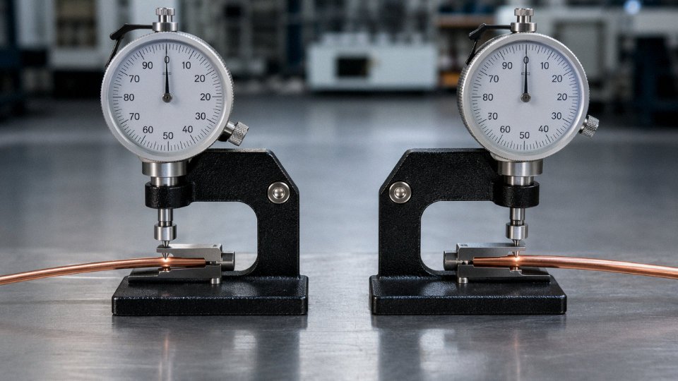
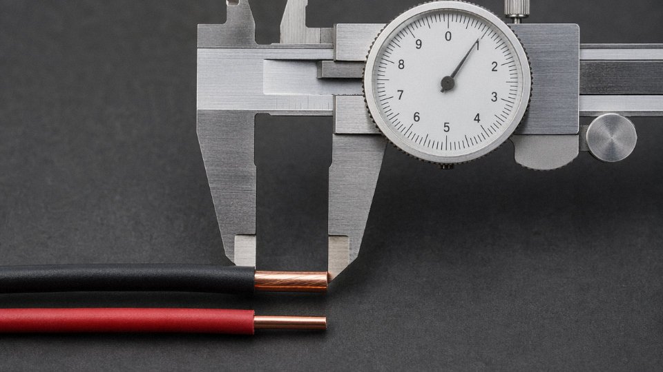
Use calipers on the bare conductor — 12 AWG measures approximately 2.05 mm, 20 AWG approximately 0.81 mm. In practice, if you’re pulling wire from a reel without calipers handy, check the jacket print. NEC-compliant cables must have the AWG size printed on the outer jacket at regular intervals, typically every 12 to 24 inches depending on the cable type. On older installations where the print has worn or the jacket has been cut back, a dial caliper takes about ten seconds and removes all guesswork. I’ve seen technicians rely on visual comparison alone and get it wrong when different insulation wall thicknesses made the overall OD misleading.
Does gauge affect wire flexibility?
Significantly. 20 AWG wire bends easily, routes through tight harness channels, and tolerates repeated flexing — which is why you see it in control panel wiring, sensor leads, and signal harnesses almost universally. Stranded 20 AWG is even more flexible. 12 AWG is noticeably stiffer, especially in solid form, and generally requires a minimum bend radius of around 5× the cable’s outer diameter to avoid fatiguing or kinking the conductor. In conduit work this rarely matters, but in enclosure wiring where someone is trying to dress cables into a tight bundle, 12 AWG solid will fight back. Installers sometimes underestimate this and end up cracking insulation at junction box knockouts.
Can 20 AWG wire be used in a conduit sized for 12 AWG?
Physically, yes. Electrically and from a code standpoint, it depends entirely on how the circuit is protected and labeled. The overcurrent device must be rated appropriately for 20 AWG — typically 5 A for signal applications or per the insulation’s rated ampacity, whichever is lower. Leaving a 20 A breaker feeding a 20 AWG conductor in a shared conduit is the problem, not the conduit size itself. Color coding and jacket labeling matter here too: if a future technician opens that panel and sees what looks like a normally sized circuit, they may assume it’s protected accordingly. Clear labeling at both ends, and at any junction box along the run, prevents dangerous mis-connections years later.
What gauge wire do solar PV systems typically use?
Residential PV string wiring — the runs between panels and the combiner or inverter input — most commonly uses 12 AWG (4 mm²) rated USE-2 or dedicated PV Wire at 600 V or 1000 V DC. The DC rating matters; standard NM-B at 600 V AC is not an appropriate substitute outdoors on a rooftop. For longer home-run distances on commercial systems, 10 AWG (roughly 6 mm²) or 8 AWG (roughly 10 mm²) are common to keep voltage drop under the 2% guideline that most inverter manufacturers specify for optimal system efficiency. The actual gauge choice depends on string current, run length, and whether the installer is designing for minimum material cost or minimum losses over a 25-year system life — those objectives pull in opposite directions.
Does Jinda manufacture both 12 AWG and 20 AWG equivalent cables?
Yes. Jinda produces the full conductor size range from 0.5 mm² (approximately 20 AWG) through 1000 mm² for power transmission, across standard insulation and jacket materials including PVC, XLPE, rubber, and halogen-free compounds. Production is certified to IEC, GB/T, and project-specific standards, with documentation packages available for international supply contracts. For custom specifications — unusual conductor constructions, specific voltage ratings, paired or shielded configurations — the engineering team can accommodate non-catalog requirements, which is relevant for procurement managers sourcing for large-scale projects rather than off-the-shelf stock.