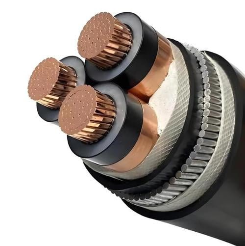
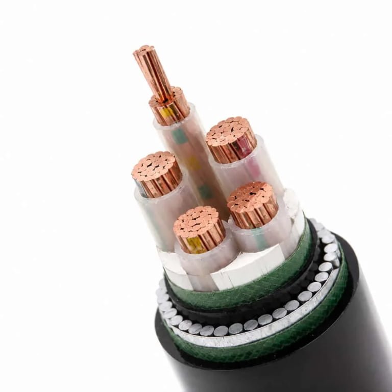
Specify the wrong wire type on a procurement order — solid where stranded was needed, or bare copper where tinned was required — and the consequences show up fast: insulation cracking within months on a flex application, premature corrosion in a humid enclosure, or a failed inspection that holds up an entire production line commissioning. Rework and reorder costs are rarely trivial. On larger projects, a single substitution error can cascade into weeks of delay and warranty disputes that nobody budgeted for.
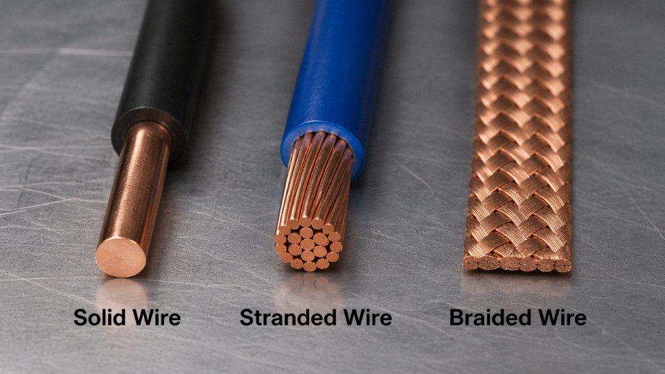
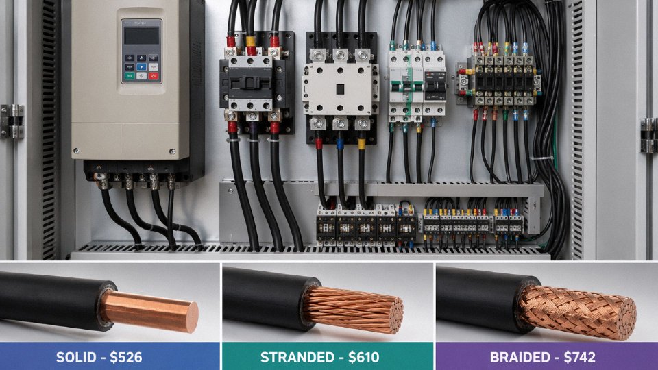
The three types of wire are solid wire, stranded wire, and braided wire. Solid wire is a single continuous conductor suited to fixed installations where it won’t be flexed repeatedly. Stranded wire bundles multiple thinner conductors together for flexibility and vibration resistance. Braided wire weaves or plaits conductors into a flat or tubular form used mainly for shielding, grounding straps, and high-flex connections.
What makes this classification genuinely useful — rather than just textbook trivia — is understanding why each construction exists and where choosing the wrong one costs you. The resistivity difference between copper and aluminum already shapes conductor sizing decisions before you even get to construction type; a 7-strand AWG 12 stranded conductor can survive 10,000 to 100,000 flex cycles under repeated bending, while the solid equivalent typically gives out before 1,000 cycles. That gap has real consequences on the plant floor.
Solid Wire: Construction, Electrical Characteristics, and Best-Fit Applications
Solid wire is exactly what the name says — a single, unbroken cylindrical conductor running the full length of the cable. No strands, no twisting, no air gaps. The conductor starts as a rod (copper at roughly 8 mm diameter is typical for rod-break drawing lines, aluminum somewhat larger) and gets pulled through a succession of progressively smaller dies until it reaches the target gauge. That drawing process does more than just reduce diameter: it work-hardens the metal, aligns the grain structure longitudinally, and produces a surface finish consistent enough that automated stripping and termination equipment can process it at high throughput without mis-feeds or inconsistent strip depths. Dimensional tolerance on a well-drawn solid copper conductor typically sits within ±0.01–0.02 mm of nominal — tight enough to matter when you’re running thousands of terminations per shift on IDC connectors.
Tensile strength of finished copper solid wire usually lands in the 200–250 MPa range, depending on the drawing reduction ratio and whether the conductor gets annealed afterward. Annealed (soft-drawn) copper sacrifices a bit of tensile strength for improved ductility, which helps during installation — you can straighten it, make a 90-degree sweep, and it holds the shape. Hard-drawn and medium-hard grades are stiffer and show up more in utility overhead applications where sag resistance matters more than bendability.
Electrical Performance — Where Solid Wire Has a Genuine Edge
Copper’s resistivity sits at approximately 1.68 × 10⁻⁸ Ω·m at 20°C. A solid conductor of a given cross-section uses every bit of that metal without the geometric penalty that stranded construction introduces — inter-strand voids in a stranded conductor mean the effective fill factor is something like 75–93% depending on strand count and lay, so the actual metal cross-section is slightly less than the nominal mm² implies. Solid wire avoids that entirely.
Solid wire has lower DC resistance per nominal cross-section than stranded wire of the same AWG or mm² rating.True
Stranded conductors contain inter-strand air gaps that reduce actual metal fill to roughly 75–93% of nominal cross-section, increasing DC resistance relative to a solid conductor at the same gauge designation.
At power frequencies — 50 or 60 Hz — skin effect is practically negligible for the gauges where solid wire is actually used (AWG 14 down to AWG 4 covers most residential and light commercial fixed wiring). The skin depth in copper at 60 Hz is around 8.5 mm, which is far larger than the radius of any conductor in that gauge range. So you’re getting full conductor utilization, not just surface conduction. That makes the resistance calculation clean and predictable, which matters for voltage-drop calculations on long feeder runs.
The other thing procurement engineers sometimes overlook: solid wire has no inter-strand crevices to trap moisture. In a compromised jacket or poorly sealed conduit entry, stranded conductors can wick moisture along the strand interstices for surprising distances, setting up galvanic conditions and corrosion pitting well inside a panel or enclosure. Solid wire doesn’t give moisture anywhere to hide.
Where Solid Wire Belongs — and Where It Fails Fast
Fixed residential branch circuits, NM-B runs through stud bays, THHN pulled into rigid conduit for panel homerun circuits, underground direct-burial feeders — these are solid wire’s natural habitat. The wiring goes in once and doesn’t move again for twenty or thirty years. Stiffness is irrelevant. The cost difference over stranded is real: solid copper conductors typically run 5–15% less per meter than equivalent stranded at the same cross-section, depending on strand count and market conditions.
The mechanical story turns ugly quickly under repeated bending. Copper work-hardens with each flex cycle; for solid conductors at AWG 10 and heavier (roughly 6 mm² and above), fatigue crack initiation can occur in fewer than 1,000 flex cycles under typical bending radii. Lighter gauges last longer but still fracture eventually. In practice, the failure mode at terminations is especially nasty — an electrician who re-torques a lug or repositions a solid AWG 8 conductor two or three times during commissioning may have already initiated a crack at the bend point. The connection looks fine, passes initial continuity, and then opens under thermal cycling six months later.
Pulling solid wire through conduit in gauges above AWG 4 is also genuinely miserable. The stiffness-to-weight ratio makes routing through bends slow and sometimes requires pulling tensions that risk insulation damage at conduit edges. Most experienced wiremen shift to stranded at AWG 4 and above for conduit work, regardless of what the code permits.
The decision isn’t complicated: if the conductor stays stationary after installation and the run is straightforward enough that stiffness doesn’t create pull-force problems, solid wire is the economical and electrically sensible choice. If anything moves — machine connections, flexible conduit drops, panel doors with wiring harnesses — solid wire will eventually crack, and “eventually” can be uncomfortably soon.
Stranded Wire: How Strand Count and Lay Configuration Determine Performance
The shorthand “stranded wire is more flexible than solid” is technically accurate but operationally useless on its own. What actually matters on the plant floor — and in a procurement spec — is which stranding class you’re buying and whether it matches the mechanical duty cycle of the application.
Stranding Classes and What the Geometry Actually Does
IEC 60228 and ASTM B8/B174 are the two governing standards that define stranding classes internationally. They don’t use identical terminology, but the underlying logic maps closely enough for practical cross-reference.
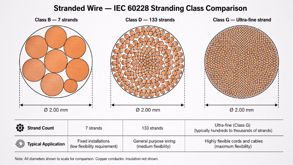
Class B (7-strand for smaller cross-sections, 19-strand for larger) is the workhorse of building wire and fixed-installation power cable. Seven strands arranged in a single-layer helix around one central wire gives you a compact, near-circular cross-section, predictable resistivity, and just enough flexibility to pull through conduit — but that’s roughly where the flex story ends. The helical lay length (the axial distance for one complete 360° wrap of the outer strand layer) is kept relatively long in Class B, which reduces strand-on-strand abrasion at the cost of limiting dynamic flex performance.
Classes C and D move into rope-lay territory — multiple bundles of wires, each bundle itself twisted before the assembly is laid up together. A Class D conductor at 35 mm² might carry 133 individual wires rather than 19. More strands means each individual wire is finer, the bend radius under which the conductor buckles internally gets smaller, and the cable can follow tighter routing paths without the outer strands trying to “birdcage” away from the center.
Class G and H are fine-strand and ultra-fine-strand constructions used in welding cable, portable cords, and mining trailing cable. Individual strand diameters here can run below 0.2 mm in some constructions. These cables are literally designed to be dragged across concrete floors, coiled and uncoiled continuously, or articulated by a robotic arm thousands of times per day.
Flex-Life Numbers and What They Depend On
A Class B 7-strand AWG 12 conductor typically survives 10,000–100,000 flex cycles, while a Class G fine-strand equivalent under the same bend-radius test conditions can exceed 1 million cycles.True
Flex-life figures are consistent with IEC 60228 classification logic and published conductor fatigue testing; the wide range for Class B reflects the strong dependency on bend radius — tighter bends collapse toward the lower bound rapidly.
That range for Class B is wide on purpose. Bend radius is the dominant variable: take a Class B cable to a tight bend radius — say 3× the cable outer diameter — and you’ll be replacing it well before the 10,000-cycle lower bound. Run the same conductor at 8–10× OD and it might survive three or four times longer. Class G constructions are more forgiving of tight radii precisely because individual wire diameter is so small that the strain per wire stays below fatigue threshold even when the overall cable bends sharply.
For machine tool wiring, robotic arm cable, and shipboard circuits where the cable moves during every operational cycle, Class D or G isn’t a premium upgrade — it’s a maintenance cost decision. A panel builder who saves a few dollars per meter on Class B cable inside a moving cable carrier is typically looking at a wiring failure inside 18–24 months. That’s a service call, downtime, and often collateral damage to connectors.
Procurement and Installation Realities
Stranded wire runs roughly 5–15% more per kilogram than equivalent solid wire, depending on strand count, wire diameter, and whether annealing is specified. The cost delta comes from additional drawing passes to achieve fine wire diameters, the annealing cycle (critical for maintaining ductility in fine strands), and the stranding operation itself.
Two installation details catch buyers off guard. First, stranded conductors cannot be landed directly under a bare screw-clamp terminal — strand splaying under clamping pressure creates high-resistance hot spots that are notoriously difficult to find in a live panel. Crimped lugs or wire ferrules are mandatory; a good-quality ratchet crimper and the right ferrule series (Weidmüller, Phoenix Contact, or equivalent) are not optional extras. Second, for large cross-sections above roughly 35 mm², stranded construction is the only practical choice for field routing through conduit bends. Solid rod at that size will not flex through a 90° elbow without specialized equipment and usually specialized conduit dimensions.
Those two realities combined explain why stranded wire dominates industrial power distribution, marine and offshore cable runs, renewable energy balance-of-system wiring, and most infrastructure projects where cable is pulled, terminated by hand, and expected to last 20 or more years in service.
Braided Wire: Shielding, Grounding, and High-Frequency Signal Integrity Functions
Braided wire occupies a fundamentally different design space than solid or stranded wire. It isn’t primarily about routing current from point A to point B — it’s about managing interference, handling movement, and providing reliable low-impedance paths in applications where a rigid conductor would crack, loosen, or simply fail to do the electromagnetic job.
Construction: What Makes a Braid a Braid
The basic geometry is straightforward: many fine wires — typically 24 AWG to 34 AWG individually — are wound in opposing helix angles over a core, with alternating carriers crossing over and under each other in a repeating interlace pattern. The result is a tubular mesh that can flex in virtually any direction without any single wire bearing the full bending stress. In grounding and busbar applications, that same braid is either flattened into a strap or left tubular and terminated at both ends with crimped or soldered lugs.
The critical geometric parameter is optical coverage percentage, which describes how much of the underlying surface the braid physically covers when viewed from the outside. Most effective shielding specifications target 85–98% coverage. Getting from 85% to 95% isn’t just a matter of adding more wire — it depends on the braid angle (the helix angle of each carrier relative to the cable axis), pick count (number of crossover points per unit length), number of carriers, and strand diameter. Engineers adjust these four variables together to hit a target coverage figure without adding so much copper that the cable becomes stiff or the outer diameter exceeds conduit fill limits.
IEC 61196, MIL-DTL-17, and UL 444 each define how braid shield performance must be specified and tested for coaxial, instrumentation, and communications cables respectively. If you’re writing a purchase specification and you don’t reference one of these, expect inconsistent results between suppliers.
Three Industrial Roles, Each With Different Failure Modes
Electromagnetic shielding is what most engineers associate with braided wire first. A copper or tinned-copper braid over a signal conductor gives the cable a low-impedance return path for induced currents, diverting interference before it corrupts the signal. In 4–20 mA instrumentation loops, even modest EMI pickup can shift a loop reading by enough to trigger false alarms or actuator responses — a real operational cost in process plants. Variable-frequency drive output cables are a particular headache: PWM switching generates broadband EMI up to roughly 30 MHz, and an unshielded cable routed near other instrumentation in a control cabinet is asking for trouble. Factory automation environments running EtherCAT or PROFIBUS face similar issues. A 95% coverage tinned-copper braid on an RG-6 coaxial cable delivers roughly 85–95 dB of shielding effectiveness at 1 GHz — the exact figure depends on termination quality, which is where a lot of well-specified cable fails in practice.
A higher optical coverage percentage always means better EMI shielding effectivenessFalse
Coverage percentage is a geometric measure of how much of the underlying surface is covered by the braid. Shielding effectiveness in dB also depends on braid material conductivity, termination method, connector backshell design, and frequency range. A 95% coverage braid with a poorly bonded connector can perform worse than a 90% coverage braid properly terminated at both ends.
Flexible grounding straps are the second application, and they’re underspecified surprisingly often. Flat tinned-copper braid straps rated for continuous currents somewhere in the 50–500 A range — depending on strap width, thickness, and ambient conditions — are the right answer wherever a rigid busbar can’t accommodate thermal expansion or equipment vibration. Transformer tanks, switchgear frames, motor housings on overhead cranes: all of these move relative to the building structure, and a solid copper bar welded or bolted across that joint will eventually crack. The braid absorbs the micro-movement without fatiguing.
High-ampacity flexible conductors for battery interconnects and UPS systems are the third role, and it’s one that’s grown considerably with lithium-ion battery adoption. Lithium cells expand and contract with each charge cycle — typically fractions of a millimeter per cell, but across a large pack that adds up — and a braided copper bus strap accommodates that movement continuously. Fault current capacity matters here too: the strap has to survive a short-circuit event without melting open.
Specifying Braided Wire Correctly
Purchasing braided wire without nailing down the full parameter set is a common source of field problems. The key variables:
| Parameter | Typical Range | What It Drives |
|---|---|---|
| Braid material | Bare copper, tinned copper, silver-plated copper | Temperature rating, oxidation resistance, contact resistance at termination |
| Coverage percentage | 85–98% | EMI attenuation, flexibility, cable OD |
| Strap width × thickness | Application-specific | Current rating, mechanical fit |
| Temperature rating | 60°C–200°C+ depending on jacket | Service environment compatibility |
| Applicable standard | IEC 61196 / MIL-DTL-17 / UL 444 | Testing protocol, documentation requirements |
Silver-plated copper braid is worth specifying for applications above roughly 150°C — tinned copper starts losing its oxidation protection at sustained elevated temperatures, which increases contact resistance at terminations over time. For standard industrial environments, tinned copper is the practical choice: it solders cleanly, resists corrosion reasonably well, and costs noticeably less than silver-plated.
The tested attenuation value in dB, not just the coverage percentage, should appear in any serious procurement specification. Coverage is easy to measure geometrically; attenuation at the operating frequency range is what actually matters on the factory floor.
Side-by-Side Comparison: Selecting the Right Wire Type Against Five Engineering Criteria
The three wire types don’t compete on the same playing field — they solve different problems. That said, procurement teams and panel designers routinely pick the wrong type, not from ignorance but from habit. The table below gives you a working reference; the analysis that follows is where the real decisions get made.
Reference Comparison Table
| Criterion | Solid Wire | Stranded Wire | Braided Wire |
|---|---|---|---|
| Flex-life (bend cycles) | < 1,000 cycles under repeated bending | 10,000–100,000 cycles (strand count and lay dependent) | Effectively unlimited in flat-strap form; shielding braid rated similarly to fine-strand |
| DC resistance (AWG 12 / ~3.3 mm², copper, 25°C) | ≈ 5.21 mΩ/m | ≈ 5.35 mΩ/m (7-strand configuration) | Varies — shield braid optimized for coverage, not low resistance per se; grounding strap ≈ 4–6 mΩ/m depending on braid angle and coverage |
| Unit cost index (relative, copper, per kg) | 1.00 (baseline) | 1.05–1.20 (drawing and annealing steps add cost; finer strands cost more) | 1.30–1.70 (braiding machinery, tighter tolerances, coverage verification) |
| EMI shielding | None | None without outer braid or foil | 85–98% coverage optical (coverage % drives attenuation; 95%+ needed above 10 MHz) |
| Termination method | Screw terminal, crimp, solder — all clean; no ferrule typically required | Ferrule or end-cap required in screw terminals to prevent fraying; compression lug for large sizes | Drain wire pigtail, flat lug, or direct crimp to chassis; coverage must be terminated 360° for full shielding effect |
The resistance difference between solid and 7-strand AWG 12 — roughly 0.14 mΩ/m — sounds trivial. Over a 50-metre panel run it adds up to about 7 mΩ total, which is genuinely negligible at 20 A. But in precision instrumentation circuits or in battery management systems where millivolt-level accuracy matters, that penalty is worth tracking. Usually it isn’t the deciding factor, but you should know it exists.
Where Each Type Wins Clearly
Solid wire is the right call for fixed residential and light commercial wiring up to 240 V and roughly 100 A, conduit home-runs that go in once and stay put, and anywhere installation simplicity translates to labor savings at scale. No ferrules, no fraying, clean termination. The cost savings compound quickly on large residential projects.
Stranded wire takes over the moment the conductor moves — even occasionally. Long conduit pulls benefit from its flexibility during installation, which reduces conduit jamming and jacket damage, even if the final installation is static. For conductor cross-sections above 35 mm², practically all industrial distribution and renewable energy balance-of-plant wiring defaults to stranded simply because handling rigid aluminum or copper bar at that size becomes a mechanical problem on its own.
Braided wire wins on shielding, grounding straps, and any vibration environment. In VFD-fed motor circuits and process instrumentation, it’s not optional — it’s a fault-prevention measure.
Common Specification Mistakes Worth Avoiding
Over-specifying stranded in fully static panel wiring is probably the most common wasteful decision. The wire goes in, never moves again, and you’ve paid a 10–20% unit cost premium for flex-life you never use. On a 10,000-metre panel build, that difference is real money.
The opposite error — under-specifying shielding coverage on VFD output cables — is more damaging. Shielding coverage below roughly 85% optical on a VFD cable allows conducted EMI to couple into adjacent signal cables, and the symptom is nuisance drive trips that look intermittent and take days to diagnose. Specifying 95%+ coverage and properly terminating both ends of the shield solves it before it starts.
Using solid wire in panel wiring that gets disturbed during maintenance is a failure Jinda’s application engineers see regularly when reviewing incoming cable schedules. Solid conductors fatigue and fracture at terminal blocks after three or four re-torquing cycles. The break often doesn’t show visually; it shows as an intermittent open circuit during commissioning or, worse, during operation.
A 7-strand stranded AWG 12 copper conductor exhibits measurably higher DC resistance than an equivalent solid conductor of the same cross-section.True
Stranding introduces a helical lay path slightly longer than the straight conductor axis, and the inter-strand contact geometry increases effective resistivity marginally. The IEC 60228 Class 2 benchmark confirms stranded resistance is permitted to be slightly higher than solid — approximately 2–3% in practice for a 7-strand configuration.
Specification documents that reference this table directly should note that braided shielding coverage percentages must be verified by the supplier against the applicable frequency range — 85% coverage adequate at 1 MHz is insufficient at 100 MHz, and the two numbers look identical on a data sheet if the test frequency isn’t stated.
Material and Insulation Choices That Apply Across All Three Wire Types
Wire type — solid, stranded, or braided — tells you about geometry and mechanical behavior. Conductor material and insulation tell you about everything else: how much current fits through a given cross-section, how long it survives the environment, whether it passes a smoke-toxicity test, whether it solders cleanly. These are independent axes of specification, and conflating them causes real procurement mistakes. I’ve seen projects where the correct stranding class was chosen and the wrong insulation system was approved, resulting in a full cable replacement inside 18 months.
Copper vs. Aluminum: Getting the Trade-Off Honest
Copper sits at roughly 58 MS/m (IACS 100%) and annealed tensile strength in the 200–250 MPa range. Those two properties together explain why it dominates fine-gauge wire, flexible conductors, and any application where the termination method is a crimped lug or a soldered joint. You cannot practically make a Class 5 or Class 6 stranded conductor from aluminum — the fine strands work-harden and break under flex, and the oxide layer that forms on bare aluminum makes reliable small-terminal connections genuinely difficult without special crimp tooling and inhibitor compound.
Aluminum conductors require approximately 1.6× the cross-sectional area of copper to carry equivalent current.True
Aluminum's conductivity is approximately 35 MS/m (IACS 61%) versus copper's 58 MS/m. To carry the same current at the same resistive loss, cross-section must scale inversely with conductivity, giving a factor of roughly 58/35 ≈ 1.66×, conventionally rounded to 1.6× in engineering practice.
Where aluminum earns its place is in large feeder cables, typically 95 mm² and above, and overhead transmission lines. Aluminum’s density is about 2.7 g/cm³ against copper’s 8.96 g/cm³. On a long overhead span or a building riser feeding a main distribution board, that density difference translates into real structural and cost consequences — lighter conductors mean smaller support structures and lower installed cost per ampere-meter of capacity. For bulk infrastructure procurement, aluminum’s cost per kilogram is typically 40–60% lower than copper, though the spread fluctuates with commodity markets. The calculation favors aluminum decisively once you’re running hundreds of meters of large-section cable and the installation is fixed, not repeatedly flexed.
The rule of thumb in practice: copper for anything below 95 mm², anything flexible, anything needing reliable small-terminal terminations. Aluminum for fixed, large-section, long-run power distribution where weight and cost per ampere-kilometer drive the decision.
Insulation Systems: Rated Temperature Is Not the Whole Story
PVC is the workhorse — rated 60–90°C depending on compound grade, cheap, easy to extrude onto all three wire types, and adequate for most dry indoor building wire. Its weakness is chemical resistance and behavior in fire. It releases hydrogen chloride when it burns, which is why it’s disqualified from a growing list of infrastructure applications.
XLPE (cross-linked polyethylene) handles 90°C continuous with short-circuit ratings up to 250°C, and its dielectric strength runs 20–30 kV/mm depending on compound quality and processing. That combination makes it the default choice for medium-voltage power cable, whether the conductor is solid aluminum or stranded copper. The cross-linking process fundamentally changes the polymer’s thermal behavior — it won’t flow and deform under sustained load the way thermoplastic PVC does at elevated temperature.
LSZH (low-smoke zero-halogen) compounds are specified wherever combustion gas toxicity is regulated: rail tunnels, ship cable trays, data centers, and airports. IEC 60332 and EN 50575 are the standards to cite in the specification. The mechanical properties of LSZH are slightly inferior to PVC at low temperatures — it can become brittle below -15°C or so, depending on the specific compound — which matters on outdoor cable in northern climates.
Silicone rubber operates continuously at 180–200°C and stays flexible down to roughly -60°C. It’s the right call for braided grounding straps on furnace doors, heating element leads, and anywhere thermal cycling would crack a thermoplastic insulation.
PTFE pushes continuous service to 260°C with near-total chemical inertness. Refinery instrument loops, chemical dosing systems, and any instrumentation wire routed near aggressive process fluids. The cost premium over PVC is substantial — roughly 4–8× depending on gauge and wall thickness — so specifying it where XLPE would genuinely suffice is waste.
Tinning, Bare Copper, and When Silver Actually Earns Its Cost
Surface treatment on the conductor is a detail that procurement teams often treat as optional. It isn’t, in certain environments.
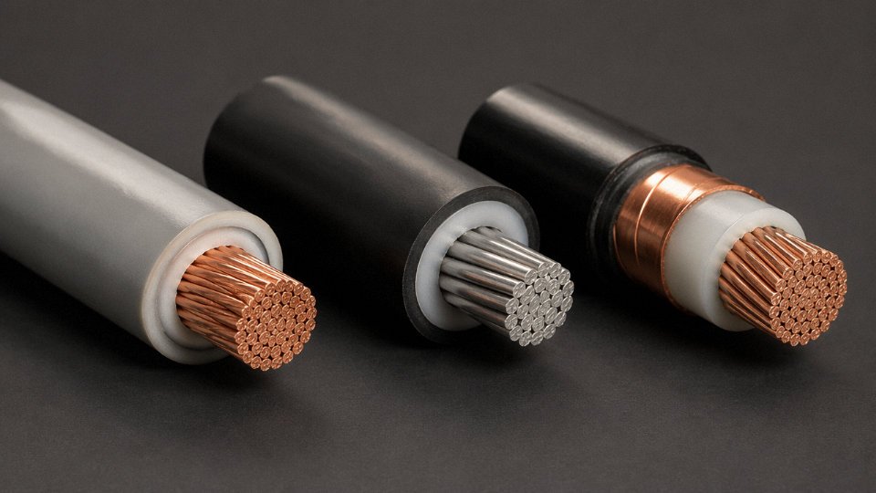
Tinned copper carries an electroplated tin layer of 1–3 µm per IEC 60228. On fine-strand and braided wire used in marine cable trays, humid switchgear enclosures, or coastal industrial plants, that thin tin layer prevents the surface oxidation that increases contact resistance over time and eventually turns a reliable ground connection into a high-impedance fault path. It also dramatically improves solderability in electronic assembly — bare copper oxidizes on the shelf, tinned copper stays solderable for years under normal storage. Expect a cost premium of roughly 5–12% over bare copper wire of the same construction, varying with tin price and coating thickness.
Bare copper is perfectly adequate for standard building wire, dry-environment panel wiring, and most fixed power installations where terminations are mechanical and the environment is controlled. No reason to pay for tinning there.
Silver plating is specific: high-frequency coaxial braid and some specialty flex applications above roughly 1 GHz. At those frequencies, current density concentrates in a thin surface layer (skin effect), and silver’s conductivity of approximately 63 MS/m — marginally above copper — reduces insertion loss in a way that actually matters for RF performance. Outside that narrow application band, silver plating is cost without benefit.
Industry-Specific Wire Type Deployment: Power, Renewables, Marine, and Industrial Automation
The solid/stranded/braided classification only becomes useful when you map it against the actual environments these products live in. Four sectors — utility power, renewables, marine and offshore, and industrial automation — account for a substantial share of global wire and cable demand, and each one pulls the three types in distinct directions.
Power Generation and Grid Infrastructure
Utility feeders are where stranded aluminum really earns its keep. A typical rural distribution project in Southeast Asia or the Middle East might call for 400 mm² stranded aluminum conductors, XLPE-insulated to IEC 60502 (up to 35 kV), run across 8–12 km of trench with multiple river or road crossings. Aluminum’s resistivity sits around 2.82 × 10⁻⁸ Ω·m versus copper’s roughly 1.68 × 10⁻⁸ Ω·m, so you’re giving up some conductivity, but at that cross-section and project scale the weight and cost difference over a 10 km route usually settles the argument in aluminum’s favor. For higher-voltage transmission work — 66 kV to 150 kV — IEC 60840 governs the product family and you typically see large-section stranded copper conductors with semi-conductive screens, not solid, because solid aluminum at those cross-sections is nearly impossible to handle in the field without mechanical damage.
Inside the substation control building the picture shifts. Instrumentation and protection cables running between marshalling kiosks and relay panels use braided copper shields, often over twisted pairs or triples, specifically because 33/11 kV transformers and bus-bar switching generate enough conducted and radiated interference to corrupt differential protection signals on unshielded cables sharing the same tray. That’s not a theoretical concern — misoperation of a distance relay due to noise on an unshielded CT circuit is the kind of event that ends careers.
Solar and Wind Renewable Energy Projects
PV string cables are a deceptively demanding specification. The conductors are fine-stranded tinned copper — Class 5 per IEC 60228 — with UV-stabilized XLPE or EVA insulation rated for 1,500 V DC and typically 90°C continuous. IEC 62930 sets the 25-year outdoor endurance requirement, which includes ozone resistance, thermal cycling, and UV exposure testing that most ordinary building wire would fail within a few years. Tinning matters here: bare copper in the micro-gaps between fine strands will oxidize at elevated temperature over a decade-long installation, creeping up contact resistance and generating hot spots at MC4 connectors.
Wind is harder. Tower cables between the nacelle and the base must tolerate continuous rotation — ±720° or more over a 30-year service life, per the loading cases in IEC 61400-1. That demands purpose-engineered torsion-resistant stranded constructions with specially laid inner elements; standard Class 5 stranded cable will unlay and birdcage under that regime within a few years. In the nacelle itself, braided shielded pairs on pitch and yaw control signal cables are non-negotiable. Servo drive switching frequencies are high enough that an unshielded encoder feedback cable running alongside the main power chain will pick up enough noise to cause position errors, and a turbine misreading blade pitch by even a couple of degrees in high wind is a serious mechanical event.
Marine and Offshore
IEC 60092 and Lloyd's Register type approval require tinned fine-strand copper conductors for shipboard cables in salt-atmosphere environmentsTrue
IEC 60092-353 and Lloyd's Register Rules for the Manufacture, Testing and Certification of Materials specify tinned copper conductors for marine cables, citing corrosion resistance in salt-laden atmospheres as the primary justification.
Marine cable tray environments are genuinely hostile. Tinned Class 5 or Class 6 conductors resist the slow corrosion that bare copper develops where insulation has minor mechanical damage — common on working vessels. LSZH or EPR insulation is mandatory for accommodation spaces and escape routes because halogenated smoke in a confined ship corridor is a casualty multiplier. Braided copper shields become critical whenever instrumentation cables share trays with high-current power cables, which on an offshore platform is almost everywhere. There’s rarely the physical separation that land-based plant can afford.
Industrial Automation and Robotics
This is where strand count really determines whether you get six months of service life or six years. Robot umbilicals, drag-chain assemblies, and AGV power tails all involve continuous flexing — not occasional movement, but repetitive cycling at rates that accumulate 10 million bend cycles over a machine’s service life. Class 6 or Class H fine-stranded conductors with polyurethane jacketing are the standard here. A 7-strand AWG 12 solid conductor, by contrast, would likely fatigue to failure somewhere between a few hundred and a few thousand cycles under the same bending radius — and on an automotive body shop robot running three shifts, conductor failure means unplanned downtime that typically costs several thousand dollars per hour by the time you count lost production, maintenance labor, and restart waste.
The conductor fatigue math is unforgiving. Specify the wrong flex class on a drag chain because it was cheaper at purchase, and you’ll replace it two or three times over the life of the machine, spending several times the original cost difference. Procurement managers who’ve been through that once tend to over-specify on the next project.
Procurement and Quality Assurance: What to Verify Before Placing a Bulk Cable Order
Buying wire at scale — whether it’s 50 drums of 95 mm² stranded copper for a substation project or a mixed order of solid and braided conductor for an industrial automation line — is where specification errors become expensive. The engineering work upstream means nothing if the material arriving on site doesn’t match what was quoted. These checks aren’t bureaucratic box-ticking; they’re the difference between a project that commissions on schedule and one that fails its continuity tests at the worst possible moment.
Conductor Cross-Section and Resistance Verification
Never rely solely on the printed AWG or mm² label on a drum. Request a factory test certificate showing measured conductor DC resistance per IEC 60228 (for metric cross-sections) or ASTM B3 (for bare copper wire, particularly relevant in North American projects). The reason this matters: a conductor shipped as 95 mm² but measuring at an effective 88–90 mm² cross-section will show higher-than-specified resistance, and that difference compounds over a long cable run into real voltage drop — often enough to push a distribution circuit outside regulatory tolerance without any single failure being obvious at incoming inspection.
This tolerance abuse exists in the market. It shows up more often in commodity-grade product from smaller mills under cost pressure, but it’s worth verifying regardless of supplier size.
For large orders, specify drum-by-drum resistance records rather than a single lot sample certificate. Write the maximum permissible resistance value directly into the purchase contract — don’t leave it implicit. For a 95 mm² copper conductor at 20°C, IEC 60228 Class 2 allows a maximum of roughly 0.193 Ω/km; if your project voltage drop budget is tight, you may want to specify tighter than the standard permits.
A conductor labeled 95 mm² may legally pass incoming inspection on diameter alone while delivering measurably higher resistance than the IEC 60228 limit if cross-section is calculated from nominal rather than measured strand dimensions.True
IEC 60228 sets resistance limits, but some inspection protocols check physical dimensions rather than resistance directly. Measuring conductor DC resistance per-drum is the only reliable catch for this class of non-conformance.
Third-Party Certification and Compliance Documentation
For utility, infrastructure, and EPC-contracted work, current certifications need to be traceable — meaning you want the actual certificate number, the issuing laboratory name, and an expiry date you can verify independently. A photocopy of a three-year-old certificate from a lab that no longer holds accreditation is not useful documentation on a project with a warranty obligation.
EU-destined exports carry additional requirements. RoHS 2 (Directive 2011/65/EU) restricts specific hazardous substances in insulation and jacket compounds, and REACH compliance declarations are increasingly demanded by European utility and industrial clients. These aren’t optional for serious export business. Jinda holds ISO 9001 quality management certification and has undergone direct factory audits from utilities and EPC contractors across Europe, the Middle East, Africa, and Southeast Asia — which in practice means a buyer in those regions doesn’t have to start from zero on qualification.
Packaging, Drumming, and Transit Specifications
This section gets skipped in negotiations more often than it should. A stranded 35 mm² flexible conductor that spends six weeks on a container ship wound on a drum with too small a barrel diameter arrives with a permanent helical set. It won’t pull cleanly through conduit. It may not seat properly in compression lugs.
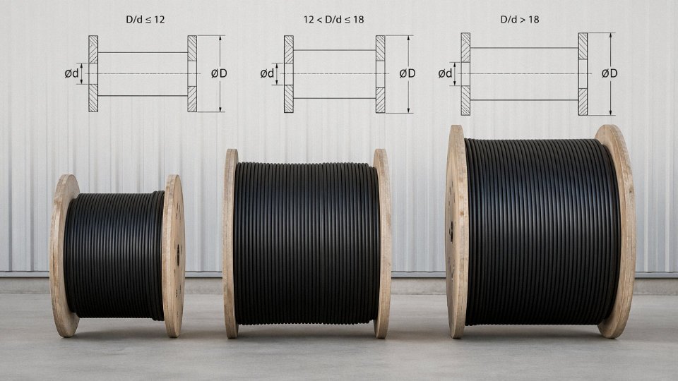
Specify minimum drum barrel diameter as at least 20× the cable outer diameter. For fine-strand or braided conductors, 25× is safer, especially on longer cable lengths where the inner layers see sustained bend stress throughout transit.
For tinned fine-strand wire shipping to humid destinations — Southeast Asian ports during monsoon season are a recurring issue in my experience — specify either nitrogen purging inside the drum wrapping or desiccant packs sealed within the outer moisture barrier. Tin coating delays oxidation, but it doesn’t eliminate it under sustained humidity if the packaging breathes.
Drum labels should show, at minimum: gross and net drum weight, reel number, production batch, cable length with tolerance (±0.5% is the working standard), and the conductor direction of lay. That last item sounds trivial until you’re pulling cable on a large site with multiple crews and discover that half the drums are wound opposite to the other half, which matters when you’re dealing with stranded conductors in tight tray installations.
Get these details in the contract, not as a verbal agreement. A well-specified purchase order is the cheapest quality assurance tool available.
Frequently Asked Questions About the Three Types of Wire
Can solid wire and stranded wire be terminated in the same connector?
Technically yes — but only if the connector is rated for both constructions. This is where a lot of panel wiring problems start. A standard screw-terminal block designed around solid wire will let stranded conductors splay under the clamping screw, and individual strands get pushed aside rather than compressed uniformly. The result is a high-resistance joint that may pass continuity testing on day one and then overheat under load six months later. Spring-cage terminals (Wago 221-series style, for example) and ferrule-crimped terminations solve this completely — the ferrule consolidates all strands into a rigid pin that behaves like a solid conductor inside the terminal. IEC 60947-7-1 governs terminal requirements for panel wiring, and any terminal block destined for Class 5 or Class 6 stranded conductors should be verified against that standard before procurement, not after the enclosure is already wired.
Is braided wire the same as shielded cable?
No, and conflating the two causes real specification errors. Braided wire is a conductor construction — bare or tinned copper strands interwoven into a tubular or flat braid. Shielded cable is a complete cable assembly that may incorporate a braided wire layer as its shielding element, but the shield is just one component of the cable. A cable can be shielded with aluminum-polyester foil or a helical serve shield and contain no braid at all. Conversely, a flat braided copper strap used to bond a transformer enclosure to a substation ground bar is braided wire functioning as a standalone conductor — no cable assembly involved whatsoever.
Which wire type is required for solar PV string wiring?
IEC 62930 (and most national PV installation codes derived from it) requires Class 5 fine-stranded tinned copper conductors with dual-rated, UV-resistant insulation for DC string cables. Solid wire is not an option here. Rooftop PV installations subject string cables to repeated thermal cycling — conductors can swing through 60°C or more between a cold night and a sun-baked afternoon — combined with low-amplitude wind-induced movement at every support clip and junction box entry. That combination will fatigue-fracture a solid conductor within a few years, often without any visible external damage to the insulation. The tinning requirement matters too; bare copper degrades faster under prolonged elevated-temperature operation at the module junction box end.
IEC 62930 prohibits solid wire conductors for rooftop PV DC string cables due to fatigue fracture risk under thermal cycling and wind-induced movement.True
IEC 62930 and derivative national PV wiring standards specify Class 5 fine-stranded flexible conductors for solar cable constructions precisely because solid conductors lack the flex-cycle life to survive the mechanical environment of a rooftop PV installation over a 25-year design life.
What is the maximum voltage rating for braided grounding straps?
The question is framed the wrong way — braided copper straps used as equipment bonding conductors are rated primarily by current-carrying capacity and bonding impedance, not voltage withstand. They’re not insulated conductors; they operate at near-zero potential difference. Per IEC 60364, equipment bonding conductors sized and installed correctly are suitable for systems up to 1,000 V AC. A 25 mm wide by roughly 1.5 mm thick flat braid strap typically carries somewhere in the 180–220 A range continuously at 70°C (the exact figure depends on ambient and how the strap is mounted) and presents well under 0.5 mΩ of impedance — substantially lower than a round conductor of the same copper cross-section because the flat geometry maximizes surface area and minimizes inductance. For fault-current bonding paths, that impedance difference is not trivial.
Does skin effect favor stranded wire over solid wire at 50/60 Hz?
It doesn’t, and this misconception comes up more often than it should. At 50 Hz, skin depth in copper is roughly 9.5–9.6 mm; at 60 Hz it’s around 9.3 mm. A 300 mm² conductor has a radius of about 9.8 mm — so even at that size, current distribution across the cross-section is nearly uniform and the AC resistance penalty from skin effect is small. Below 300 mm², which covers the vast majority of building wire and most industrial wiring, the effect is negligible. Specifying stranded wire to “improve AC conductivity” at power frequency is not an engineering justification. Specify stranded wire because the installation bends, flexes, or vibrates. Specify solid wire where it doesn’t.
What conductor classes does IEC 60228 define, and why does it matter?
IEC 60228 classifies conductors by construction flexibility. Class 1 is solid wire — single conductor, fixed installations. Class 2 is standard stranded, minimum 7 strands for cross-sections above 10 mm², also for fixed installations. Classes 5 and 6 are fine-stranded flexible constructions: Class 5 covers portable and flexible cords in general use, Class 6 goes further still — more strands, finer gauge per strand — and is used in robot cables, festoon systems, and other applications demanding very high flex-cycle life. Each step up in class number means more individual strands, smaller strand diameter, greater flexibility, longer flex life, and incrementally higher manufacturing cost per kilogram due to the additional wire drawing, bunching, and stranding passes involved. When writing a cable specification, stating “Class 5 per IEC 60228” is meaningfully different from just writing “flexible conductor” — it gives your supplier and inspector a testable, auditable target.
Can Jinda supply mixed cable schedules across all three wire types for a single project?
Yes. Jinda’s production facilities in Shandong manufacture solid and stranded power cables across low, medium, and high voltage ranges, fine-strand flexible cables, instrumentation cables with braided shields, and coaxial assemblies — all under ISO 9001 certification and relevant IEC standards. For EPC contractors managing large or complex cable schedules, consolidating supply to a single manufacturer reduces coordination overhead considerably: one set of shipping documents, consistent drum labeling, unified quality traceability, and a single technical contact who knows the full cable list rather than a different supplier for every product family. In practice, the schedule management and documentation alignment often matters as much to a project timeline as the unit pricing.
Why Wire Type Selection Directly Affects Total Project Cost and Long-Term Reliability
Getting the wire type right is not a detail. It is a project economics decision, and the downstream cost of getting it wrong usually dwarfs whatever was saved at the purchase order stage.
The Hidden Cost of Solid Wire in Dynamic Applications
Take a common scenario: a contractor specifies solid AWG 10 copper throughout a 480 V motor control panel because it’s cheaper per foot and easier to source locally. The panel gets maintained monthly — technicians opening terminal blocks, re-torquing connections, rerouting conductors slightly each visit. Solid conductors work-harden at the point of repeated bend. Within a year, you’re looking at roughly 3–5 fractures at terminal blocks, each one requiring a service call. Labor and parts typically run USD 200–500 per incident depending on the plant’s location and whether it’s a straight swap or a rewire. Over a 10-year panel life, that accumulates to somewhere between USD 6,000 and USD 25,000 in reactive maintenance — and that estimate doesn’t include the cost of the process interruption each fault causes.
The incremental cost of specifying Class B or Class C stranded wire at initial installation? Usually USD 0.05–0.15 per foot more, depending on conductor gauge and strand count. On a typical MCC panel with a few hundred feet of internal wiring, the upgrade costs a few hundred dollars. The math is not subtle. Procurement teams should run this calculation explicitly when value-engineering reviews push toward the cheapest upfront wire option, and they should put the numbers in writing for the project owner. “Lowest initial cost” is a defensible position only when total cost of ownership has actually been calculated.
Shielding Specification Is Not Optional on VFD Systems
The braided-shield argument is even more direct. A 500 kW variable frequency drive feeding an industrial pump radiates significant conducted EMI on its output cables — this is not a theoretical concern, it’s a known characteristic of PWM switching at carrier frequencies typically in the 2–16 kHz range. Run that unshielded cable near a 4–20 mA instrumentation loop and you will corrupt the signal. False readings on a flow transmitter or pressure loop can trigger nuisance trips or, worse, mask a real process deviation until something fails hard.
A single unplanned 8-hour shutdown in a refinery or chemical plant can cost between USD 50,000 and USD 500,000 depending on production value and product.True
This range is consistent with published downtime cost analyses from the process industries and is widely cited by reliability engineers and insurance actuaries; exact figures vary with plant type, throughput value, and contractual penalties.
A correctly specified VFD cable with continuous braided copper shield and drain wire — the kind that costs perhaps USD 300–600 more than the unshielded equivalent on a medium-length run — eliminates that risk entirely. Framing this as a component cost comparison misses the point. Frame it as a USD 50,000-plus risk mitigation for a few hundred dollars of cable upgrade, and the specification decision becomes obvious.
A Supply Partner Through the Full Project Lifecycle
Specification decisions like these don’t happen in isolation. They happen during cable schedule reviews, during design-build handoffs, sometimes during procurement when an engineer is trying to substitute a line item under cost pressure. Having a manufacturer engaged at that stage — one who can say “that substitution will cause you problems at the terminal block” or “your VFD run needs a shielded cable for this reason” — is genuinely useful. It is different from a vendor who ships whatever is on the purchase order and waits for the next one.
Jinda has been manufacturing cable since 1987. The operation runs from copper rod through to finished, tested reels across five production bases and roughly 470,000 m² of manufacturing space — vertically integrated enough that material traceability is real, not just a certificate. Engineers on the technical support side have worked through cable schedules for utility projects, offshore installations, renewable energy farms, and industrial automation retrofits across more than 50 countries. That breadth of application exposure matters when a procurement manager is trying to navigate a project specification in an unfamiliar market or under a standard they don’t usually work with.
The three-type classification — solid, stranded, braided — is the starting framework. But the real value in that conversation is working through gauge, conductor class, insulation system, shielding requirement, and installation environment together, before the cable is ordered. Getting it right the first time is almost always cheaper than getting it wrong and finding out during commissioning, or worse, six months into operation.