A mixed 110/220 conduit run looks harmless until someone adds a circuit, pulls the wrong conductor, or finds the raceway already packed tight above a hot ceiling. Then the issue moves from “will it fit?” to nuisance trips, failed inspections, re-pulls, and paid downtime. The right answer starts with insulation rating, conduit fill, and conductor derating—not with voltage labels alone.
Yes, you can usually run 120 V and 240 V circuits in the same conduit if all conductors are insulated for the highest voltage present, the conduit fill is within code, and ampacity derating is handled. The harder question is whether shared raceway makes maintenance, heat, and future troubleshooting worse.
That is where many installations get messy. Code permission is only the first gate; the better plant-floor decision depends on how the circuits are loaded, how many current-carrying conductors share the raceway, what insulation is on the cable, and whether the next electrician can identify the system without guessing.
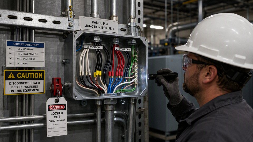
Voltage terms and circuit types
“110” and “220” are often field shorthand, not the actual nominal system voltage you should use for design. In most North American residential and light commercial work, the circuits people call 110 V and 220 V are usually 120 V and 240 V, and the conduit decision depends more on the wiring system, insulation rating, conductor count, neutral arrangement, and disconnecting rules than on the nickname.
The old terms hang around because utility voltage has changed over time, equipment nameplates tolerate a range, and electricians still use shop language. A maintenance tech may say “pull a 220 line for the compressor” while the panel schedule says 240 V, the breaker is a 2-pole breaker, and the conductors are rated 600 V. That casual language is fine at the coffee table; it is not fine on a purchase order, panel schedule, or conduit-fill calculation.
A typical North American 120/240 V single-phase service has:
- Line 1, often called L1, an ungrounded conductor.
- Line 2, often called L2, another ungrounded conductor.
- Neutral, the grounded conductor from the center tap of the transformer.
- Equipment grounding conductor, used for fault-clearing and bonding, not as a normal load return path.
- 120 V loads connected from L1 to neutral or from L2 to neutral.
- 240 V loads connected across L1 and L2.
Mechanically, that split-phase arrangement matters because the two ungrounded legs are opposite in phase. A straight 240 V load, such as many heaters, welders, air compressors, and older motors, does not need the neutral because current leaves on one line and returns on the other. A 120 V load needs the neutral because its circuit is line-to-neutral. Some appliances use both: a range or dryer may use 240 V for heating elements and 120 V for controls, lights, timers, or a small motor.
In a typical North American 120/240 V single-phase service, either ungrounded leg to neutral is nominally 120 V, while the voltage between the two ungrounded legs is nominally 240 V.True
This describes the common center-tapped split-phase service used in many residential and light commercial premises. Actual measured voltage varies with utility tolerance, loading, and site conditions.
That is why a 120 V branch circuit and a 240 V branch circuit can often occupy the same raceway in ordinary premises wiring, provided they are part of a compatible wiring system and the rest of the code rules are met. The insulation issue is usually straightforward with modern building wire because common conductors such as THHN/THWN-2 are often marked 600 V, but you still verify the marking on the actual cable or wire being installed. The harder issues are usually not voltage; they are conduit fill, ampacity adjustment, neutral counting, identification, shared disconnects, and whether the circuits belong together from a maintenance and safety standpoint.
Do not assume every “120” supply is the same kind of system. In commercial plants, a 208Y/120 V three-phase service is common. There, 120 V exists from any phase to neutral, but phase-to-phase voltage is 208 V, not 240 V. I have seen replacement heating equipment underperform because someone ordered a 240 V unit for a 208 V building; the conduit was not the problem, the system identification was. On the other side, 277/480 V systems are common for lighting, HVAC, large motors, and distribution. A “277 V lighting circuit in the same pipe as 120 V receptacle wiring” raises a different level of workmanship, labeling, maintenance exposure, and insulation verification than two circuits from the same 120/240 V panel.
There is also the machinery case. A machine may have a 480 V feed, a control transformer, and what operators call a “110 control circuit” inside the enclosure. That control voltage may be 120 V AC, 24 V DC, or something else depending on the builder. Once it is inside a listed industrial control panel or machine enclosure, different rules and standards may apply than for building branch-circuit raceways. The treatment depends on:
- The machine standard or listing involved.
- Whether the conductors are power, control, Class 2, instrumentation, or signal wiring.
- Whether the wiring stays inside the enclosure or leaves the panel.
- The insulation ratings and separation required by the equipment documentation.
- The installation method between panels, devices, and field-mounted components.
This is where procurement can accidentally buy trouble. A controls package with neat DIN rail wiring inside the panel does not automatically justify running every field device conductor in the same conduit as motor feeders. Noise, insulation class, fault energy, and maintenance access all become part of the decision.
A multi-wire branch circuit deserves its own caution because it is often misunderstood. It is not just “two circuits sharing one pipe.” In a common 120/240 V multi-wire branch circuit, two ungrounded conductors share a neutral, and the neutral carries only the imbalance when the ungrounded conductors are on opposite legs. If both ungrounded conductors are accidentally placed on the same leg, the neutral can be overloaded. Current paths, handle ties or common disconnecting means, neutral pigtailing, and simultaneous disconnection are not paperwork details; they are what keep the shared neutral from becoming a maintenance hazard when someone opens one device box and thinks only one circuit is involved.
The practical trade-off is simple enough: grouping related circuits in one raceway can reduce conduit, labor, wall penetrations, tray congestion, and installation time. The price is higher coordination burden. More current-carrying conductors can trigger ampacity adjustment, more conductors increase fill, and mixed systems can make troubleshooting slower when the next electrician opens a junction box at 2 a.m. The permission to share a raceway starts to lose its value when the circuits are from different systems, poorly identified, heat-loaded, noise-sensitive, or maintained by people who will not have the original drawings in hand.
Before applying the conduit rules, classify the source accurately:
- Is it 120/240 V single-phase split-phase?
- Is it 208Y/120 V three-phase?
- Is it 277/480 V with a separately derived lower-voltage control supply?
- Is the “110” wiring actually machine control wiring rather than premises branch-circuit wiring?
- Are any conductors shared, as in a multi-wire branch circuit?
- Are all conductors insulated for the highest voltage present in the raceway?
- Will the conductor count require fill and ampacity checks?
Once those answers are known, the code question becomes much cleaner. Without them, “Can 110 and 220 share conduit?” is only half a question, and on a plant floor, half a question is how you end up with a technically legal-looking installation that nobody wants to troubleshoot later.
Shared conduit code conditions
A 120 V branch circuit and a 240 V branch circuit are usually allowed in the same conduit if they are both power circuits rated 1000 V or less, every conductor is insulated for the highest voltage present, all conductors of each circuit stay together, and the raceway still passes fill, ampacity, identification, and local approval checks. The voltage difference itself is rarely the hard stop; misclassification, missing neutrals, derating, or equipment instructions usually cause the problem.
Under NEC 300.3(C)(1), conductors of circuits rated 1000 V or less are generally permitted in the same raceway when all conductors have an insulation rating at least equal to the maximum circuit voltage present.True
This is the central NEC rule commonly used for sharing a raceway among power circuits. The installation still has to satisfy other applicable NEC articles, local amendments, project specifications, equipment listings, and authority having jurisdiction requirements.
The practical reading is simple: if the conduit contains a 120 V circuit and a 240 V circuit, do not shop for “120 V wire” and “240 V wire.” Look at the insulation marking printed on the conductor jacket. In ordinary building wiring, individual conductors such as THHN, THWN, THWN-2, and XHHW-2 are commonly marked 600 V. That 600 V marking is the insulation rating, not the operating voltage of the load.
A 600 V insulated conductor can serve a 120 V receptacle circuit, a 208 V motor circuit, a 240 V heater circuit, or a 480 V circuit if the conductor type, size, temperature rating, wet-location suitability, overcurrent protection, and termination limits are all correct. The raceway rule cares about whether the insulation can withstand the maximum voltage between any conductor and another conductor or ground in that raceway. It does not mean the connected load is “using” 600 V.
Common markings need a little plant-floor interpretation:
- THHN is common in dry raceways, though many modern building-wire products are dual-marked.
- THWN or THWN-2 matters where the raceway is considered wet, which includes many outdoor conduits and underground raceways even when the installer thinks they are sealed. Condensation wins that argument often enough.
- XHHW-2 is often chosen where better moisture and heat performance is desired, or where the cable buyer wants a tougher insulation system for feeders.
- USE-2 is for underground service-entrance use and is not automatically acceptable for interior raceway use unless it carries another marking that permits that application, such as a dual rating. This is one of those markings worth checking before a bulk purchase; I have seen good cable rejected at receiving because it was right for burial but wrong for the indoor pull.
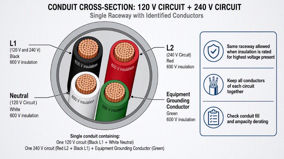
The next condition is less glamorous but just as important: all conductors of the same circuit must be routed together in the same raceway or cable assembly. For a 120 V circuit, that normally means the ungrounded conductor, grounded neutral conductor, and equipment grounding conductor where required. For a 240 V two-wire load, it means both ungrounded conductors and the equipment grounding conductor where required. For a 120/240 V multi-wire branch circuit, it means both ungrounded conductors, the shared neutral, and grounding conductor in the same raceway.
Separating a hot conductor from its neutral or return path is not just a paperwork violation. The current going out and the current coming back are supposed to sit physically near each other so their magnetic fields largely cancel. Split them into different conduits, especially steel conduit, and the raceway can heat due to induced current and magnetic effects. You can also create nuisance voltage, higher impedance, odd troubleshooting readings, and ugly electromagnetic interference near sensitive equipment. In a PVC conduit the heating mechanism is different, but the circuit still fails the grouping principle and creates maintenance hazards.
This is where conduit-sharing mistakes show up after the electrician has already made the pull:
- One 120 V hot is added to a conduit, but its neutral is borrowed from a different junction box.
- A 240 V heater circuit is routed in one raceway while the equipment grounding conductor is picked up elsewhere.
- A multi-wire branch circuit has both hots in the conduit, but the shared neutral is run through a different sleeve “because it was closer.”
- A retrofit control cabinet gets one spare conductor repurposed without verifying what circuit its return path belongs to.
The fix is not to relabel the wire and hope. The fix is to trace the complete circuit path and keep the circuit conductors together from source to load, including through junction boxes and pull points.
Circuit identification is the other code condition that procurement people sometimes underestimate because it looks like an installation detail. It is not optional in a maintainable facility. Conductors must be identifiable at terminations, splices, panelboards, disconnects, junction boxes, and equipment. If 120 V and 240 V circuits share a raceway, the next technician opening the box needs to know which conductors belong together before a meter lead, lockout tag, or splice connector touches anything.
In practice, that means using a consistent identification method:
- Color coding where permitted and appropriate, such as black/red for ungrounded conductors and white or gray for grounded conductors, subject to local rules.
- Circuit numbers or ferrule markers at both ends, especially in control panels, MCC buckets, junction boxes, and long conduit runs.
- Panel and source identification when conductors from different panels or systems occupy the same pull box.
- Neutral grouping for multi-wire branch circuits, so the neutral is visibly associated with its ungrounded conductors.
- As-built drawings that match the field, not the tender drawing from three revisions ago.
I like printed sleeve markers better than handwritten tape in oily or humid plants. Sharpie on vinyl tape looks acceptable on commissioning day and turns into archaeology after a summer above a press line.
The counter-intuitive point is that voltage difference is often less restrictive than circuit class. Two power circuits at different voltages may share a conduit under the usual 1000 V-or-less insulation rule. A power circuit and a low-energy signal circuit may be much harder to combine, even if the signal voltage is tiny. The reason is not just insulation stress; it is separation by circuit type, noise immunity, fire safety function, listing limits, and the way different NEC articles treat Class 2, fire alarm, communications, and control circuits.
| Same-conduit case | Usually acceptable? | Main condition or concern | Practical buyer/installer note |
|---|---|---|---|
| 120 V and 240 V branch circuits | Often yes | All conductors insulated for highest voltage present; each complete circuit kept together; fill and derating checked | Common with 600 V THHN/THWN-2 or XHHW-2 conductors, but identify circuits clearly in boxes |
| 120 V and 277 V lighting circuits | Often yes, if both are power circuits under the applicable rules | Insulation must cover the highest voltage; neutral identification and system identification become more important | Do not mix neutrals between systems; verify panel source and grounding system |
| 24 V Class 2 controls with power conductors | Often no, unless specific NEC allowances and insulation/barrier conditions are met | Class 2 circuits have separation rules; noise pickup can also cause erratic inputs | Use a separate control conduit or listed divider system unless the design is specifically approved |
| Fire alarm with power conductors | Usually restricted | Fire alarm circuit rules and survivability/listing requirements may prohibit casual mixing | Treat as a separate system design issue, not a spare-conduit convenience |
| VFD output with control wiring | Poor practice and often prohibited by equipment instructions | High dv/dt and common-mode noise from drive output can corrupt controls and stress insulation | Keep motor leads, encoder cables, analog signals, and network cables separated per drive manual |
The table is deliberately cautious. “Often yes” does not mean “always yes.” It means the general power-conductor rule may allow it, provided the rest of the installation checks out. Equipment instructions can be stricter than the broad wiring rule. Many VFD manuals, for example, tell you exactly how to route input power, output motor leads, braking resistor wiring, encoder feedback, and signal wiring. Ignoring that guidance can turn a technically energized system into a nuisance-trip machine.
Conduit fill and ampacity adjustment are the two arithmetic checks after the permission check. NEC Chapter 9 conduit-fill rules are commonly applied with a maximum fill of 40% for more than two conductors in a raceway, though the actual answer depends on trade size, raceway type, conductor size, insulation type, and the number of conductors. This is where “just one more circuit” gets expensive. A conduit that was easy to pull with four conductors can become a damaged-insulation problem with eight, especially through old rigid elbows with a bit of rust inside.
Ampacity adjustment can be the hidden cost. Under the NEC 310.15 adjustment approach, more than three current-carrying conductors in a raceway usually triggers derating. Equipment grounding conductors normally are not counted as current-carrying. Neutrals may or may not count depending on the circuit arrangement and harmonic content. Once derating applies, the conductor that was large enough on paper may need to be upsized, or the load split into another raceway. Upsizing then feeds back into conduit fill and pulling tension. That loop is why experienced estimators check fill and derating before issuing cable quantities, not after the conduit crew has installed 300 feet overhead.
There is a trade-off here. Sharing conduit saves raceway material, supports, penetrations, labor hours, and space in congested pipe racks. It can also reduce future clarity, increase derating, make shutdown isolation more complicated, and put unrelated maintenance work in the same box. The preference flips when the shared conduit forces larger conductors, difficult pulls, mixed-source labeling, or exposure of one production cell during maintenance on another. A tidy drawing can still be a poor maintenance decision.
The final permission comes from the adopted code edition, local amendments, authority having jurisdiction, project specification, and equipment listing instructions. A food plant with a corporate electrical standard may ban combinations that the base NEC would allow. A machine builder may require signal wiring separation as part of the listed assembly. A municipal inspector may enforce a local rule on emergency circuits or fire alarm routing that does not appear in the short answer people quote from the code book.
For a clean engineering review, collect these before approving mixed 120 V and 240 V conductors in one raceway:
- Circuit voltage and system source for every conductor.
- Conductor insulation markings and wet/dry location suitability.
- Complete circuit grouping, including neutrals and grounding conductors.
- Raceway type, trade size, total conductor count, and conductor sizes.
- Current-carrying conductor count for ampacity adjustment.
- Junction box and panel identification method.
- Equipment manuals for drives, controls, heaters, lighting systems, or packaged machinery.
- Local code edition, project electrical specification, and AHJ expectations.
Once those items are verified, the question is no longer “Can 110 and 220 share conduit?” It becomes a normal coordination decision: permitted wiring method, acceptable heat rise, pullable raceway, clear identification, and a system the maintenance crew can safely understand at 2 a.m.
Ampacity derating and conduit fill
A shared conduit can be code-permitted and still be a bad electrical design if the extra conductors trap heat, trigger ampacity derating, or make the pull impractical. The usual failure is not “110 and 220 cannot be together”; it is that the combined raceway no longer supports the breaker size, conductor insulation temperature rating, pull length, or maintenance expectations.
The thermal problem is simple on paper and annoying in the field. Every loaded conductor gives off heat proportional to current and resistance. Put more loaded conductors in the same raceway and the conduit becomes a shared heat path instead of a free-cooling space. Steel EMT in open air sheds heat differently from PVC in a sun-baked roof run, and a conduit packed through a boiler room cable tray area does not behave like the same conduit in an air-conditioned electrical room.
Which conductors count for ampacity derating?
For derating, the practical question is: which conductors are actually carrying load current during normal operation? In common NEC-based design practice, the conductors that usually count are:
- Ungrounded phase conductors, such as:
- A hot conductor on a 120 V branch circuit.
- Both hot conductors of a 240 V single-phase load.
- Three phase conductors of a 3-phase circuit.
- Neutrals that carry only unbalanced current, depending on the circuit arrangement.
- In many 2-wire 120 V circuits, the neutral carries the same current as the hot, so it counts.
- In a shared-neutral multiwire branch circuit, the neutral may carry only the imbalance between phases, but the exact treatment depends on the system and code conditions.
- Neutrals of certain nonlinear loads, especially where triplen harmonics can make the neutral run hotter than a neat sine-wave calculation suggests.
- Think LED drivers, switch-mode power supplies, office panels, VFD support loads, controls, and mixed electronic loads.
- The neutral may not be a harmless return conductor in those cases.
Conductors that usually do not count toward ampacity adjustment include:
- Equipment grounding conductors.
- Bonding jumpers.
- Certain neutrals under specific balanced circuit conditions.
That last phrase matters. I have seen crews casually say, “grounds and neutrals don’t count,” and that shortcut is wrong often enough to burn time on inspections. Equipment grounding conductors normally do not count because they are not intended to carry continuous load current. Neutrals need more care because some are current-carrying by design, some carry only imbalance, and some carry harmonic current that deserves respect.
If more than three current-carrying conductors are installed in one raceway, ampacity adjustment usually becomes a design check rather than an afterthought.True
NEC 310.15 ampacity adjustment rules commonly require derating when a raceway contains more than three current-carrying conductors, though the exact adjustment depends on conductor count, wiring method, temperature rating, and applicable code edition.
Why the “more than three” benchmark changes the design
The common trigger point is more than three current-carrying conductors in the raceway. Once you pass that point, the allowable ampacity of the conductors may need to be adjusted downward. That does not automatically kill the installation, but it can change the economics quickly.
A typical design path looks like this:
- Choose the conductor size based on load, breaker, terminal temperature rating, voltage drop, and installation conditions.
- Count the current-carrying conductors in the raceway.
- Apply the ampacity adjustment factor if required.
- Apply ambient temperature correction where needed.
- Check that the final allowable ampacity still supports the overcurrent device and load.
- Check conduit fill and pull feasibility.
- Rework the layout if any one of those checks fails.
Derating does not reduce the breaker setting by magic; it reduces the ampacity you are allowed to assign to the conductor in that installation. If the adjusted ampacity falls below what the circuit requires, you have only a few honest choices:
- Increase conductor size.
- Increase conduit trade size to manage fill and pulling conditions.
- Reduce the number of circuits in that raceway.
- Split 120 V and 240 V circuits into separate raceways.
- Re-route away from heat sources or high ambient areas.
- Reconsider load grouping and panel location.
The trade-off is familiar to anyone who has bought copper by the drum. Combining circuits may save raceway, hangers, penetrations, and labor. But if the combination forces larger conductors and a larger conduit, the saving can disappear, especially on long industrial runs with multiple bends, firestopping, or stainless fittings. The preferred choice flips when the labor saved by one conduit is less than the material, pulling, heat, and future-maintenance cost created by that same conduit.
Conduit fill is not just a percentage
Conduit fill is the space taken up by the insulated conductors inside the raceway. The calculation uses conductor outside diameter, not just copper size. A compact insulation type can change fill. So can conductor construction, insulation rating, and whether the cable product is listed for the wiring method being used.
NEC Chapter 9 is the usual reference point, and a common maximum fill benchmark is 40% for more than two conductors in a raceway. That number is not a comfort target. It is a maximum under normal conditions, and a conduit at 39% fill can still be miserable to pull if the route is poorly laid out.
Factors that make a “legal” fill calculation behave badly include:
- Long pull length: friction accumulates; the last third of the pull is where insulation gets abused.
- Too many bends: a legal bend total can still be punishing if bends are tight, back-to-back, or poorly aligned.
- Raceway material: PVC, EMT, rigid steel, flexible metal conduit, and liquidtight have different pull behavior.
- Insulation surface: some jackets pull smoothly; others drag more than expected.
- Lubricant compatibility: wrong lubricant can attack insulation or leave a mess that makes later work unpleasant.
- Pulling method: mule tape, fish tape, tugger setup, sheave alignment, and crew coordination all matter.
- Future additions: a raceway filled near the limit has no practical spare capacity.
- Maintenance access: crowded junction boxes and packed conduits turn troubleshooting into panel archaeology.
This is where engineering math and installation judgment part company a little. A CAD layout may show a clean run from panel to machine, but the installer may be looking at a route over a mezzanine, around a duct bank, past a steam line, and through a box that already has three couplings and a questionable locknut. If the plant has seasonal humidity or dust, even opening pull boxes later can become a safety and housekeeping job.
Heat from the room still counts
Ampacity tables are not permission to ignore the surrounding plant. Ambient temperature correction can be just as important as conductor count. Rooftop conduit, bundled raceways, hot process areas, ovens, compressor rooms, boiler rooms, and crowded electrical spaces can all reduce how much current a conductor can carry safely.
Watch these conditions closely:
- Rooftop exposure: sunlight and roof surface temperature can push conductors well above normal ambient assumptions.
- Bundled conduits: several raceways tied together or packed tightly on trapeze supports lose heat less effectively.
- Crowded electrical rooms: transformer heat, poor ventilation, and full gutters can raise local temperature.
- Industrial heat sources: ovens, furnaces, steam headers, hydraulic power units, dryers, and curing lines create zones where a standard branch-circuit assumption may be too optimistic.
- Continuous loads: circuits running near load for long periods create a different thermal profile than intermittent receptacle use.
The boundary here is important: derating and fill checks do not prove the circuit is good under every operating condition. They prove it against the assumptions used. If the actual installed route changes, if the load mix changes, or if the conduit ends up in a hotter area than planned, the calculation needs to be revisited.
Proposed calculation sidebar: combined conduit versus separate conduits
Use this as a decision model, not as a finished design. The conductor sizes, insulation ratings, raceway type, terminal ratings, and local code edition still have to be checked for the actual job.
Assume the project has:
- Two 120 V branch circuits.
- One 240 V single-phase branch circuit.
- Separate neutrals for the two 120 V circuits.
- One equipment grounding conductor sized for the applicable circuit arrangement.
- All conductors rated 1000 V or less and insulated for the maximum voltage present in the raceway, as required by the shared-raceway rule.
| Design option | Conductors in the raceway | Likely current-carrying conductor count | Fill impact | Derating decision points |
|---|---|---|---|---|
| One shared conduit | 2 hot conductors for the 120 V circuits, 2 neutrals for the 120 V circuits, 2 hot conductors for the 240 V circuit, plus equipment grounding conductor | Usually 6, because the two 120 V neutrals carry load current and both 240 V hot conductors carry load current | Higher fill; may require larger raceway depending on conductor OD and insulation type | More than three current-carrying conductors usually triggers ampacity adjustment; ambient correction may stack on top |
| Separate conduit for the two 120 V circuits and separate conduit for the 240 V circuit | 120 V raceway: two hots, two neutrals, grounding conductor. 240 V raceway: two hots, grounding conductor | 120 V raceway usually 4; 240 V raceway usually 2 | Lower fill per conduit; more raceway material and installation labor | 120 V conduit may still require derating; 240 V conduit may avoid the more-than-three trigger |
| Three separate branch-circuit raceways | Each 120 V circuit has hot, neutral, ground; 240 V circuit has two hots and ground | Each raceway usually 2 current-carrying conductors | Lowest fill per raceway; highest raceway count | Ampacity adjustment for conductor count may be avoided, but ambient conditions still apply |
In the combined option, the electrical designer may need to upsize conductors after adjustment. That larger conductor increases outside diameter, which increases conduit fill, which may force a larger raceway. A larger raceway then changes fittings, box entries, supports, core holes, and sometimes machine termination space. I have had more than one project where a neat “single conduit” idea died because the machine junction box simply did not have practical room for the larger raceway and bend radius.
The separate-raceway option costs more in visible hardware. It may still win if it keeps conductor size down, makes pulls simpler, gives maintenance a cleaner circuit separation, and leaves room for future work. In a production plant, one avoided Saturday shutdown can pay for quite a bit of conduit.
Neutrals, grounding, and disconnects
The mistakes in mixed 120 V and 240 V conduit runs are usually not about voltage rating; they are about conductor function. A neutral, an equipment grounding conductor, and an ungrounded phase conductor are not interchangeable just because they fit in the same pipe. If the circuit relationships are wrong, the installation can pass a casual fill check and still create overloaded neutrals, dead downstream loads, nuisance trips, or energized metalwork.
A straight 240 V two-wire load, such as many resistance heaters, welders, compressors, or motor loads, often uses two ungrounded conductors and no neutral. The load is connected line-to-line, so there is no 120 V load current returning on a grounded conductor. Once the equipment has 120 V controls, receptacles, lights, timers, contactor coils, or electronics fed from that same run, the conversation changes; a grounded conductor may be required unless the control power comes from a properly installed transformer or another approved arrangement.
A 120 V load is different. It normally needs:
- One ungrounded conductor supplying the load.
- One grounded conductor, usually called the neutral, carrying normal return current.
- One equipment grounding conductor or approved grounding path for fault current and bonding.
That last item is where bad field habits show up. The green wire or metal conduit is not a “spare neutral.” It should not carry normal load current. If it does, every bonded enclosure, coupling, motor frame, junction box, and locknut in that path may become part of the return circuit. That is not just a code issue; it is a maintenance trap for the next person opening a cover with sweaty hands on a humid afternoon.
An equipment grounding conductor is not a substitute for a neutral conductor in a 120 V load circuit.True
The neutral is an intended current-carrying grounded conductor for normal load current. The equipment grounding conductor is a bonding and fault-current path, not a normal return conductor. Exceptions and legacy cases must be checked against the current applicable code and installation conditions.
Shared neutrals in multi-wire branch circuits
A shared neutral can be acceptable in a properly arranged multi-wire branch circuit, but only when the ungrounded conductors have the correct phase relationship. On a typical single-phase 120/240 V system, the two hot conductors must be on opposite legs. On a three-phase system, shared-neutral behavior depends on the phase relationship and the type of loads connected.
The mechanism is simple but often missed. If two 120 V circuits share a neutral and are on opposite legs of a split-phase system, the neutral carries only the imbalance between the two loads. If both ungrounded conductors are accidentally landed on the same leg, the neutral currents add instead of canceling. Two 16 A loads can put roughly 32 A on a neutral that someone assumed was lightly loaded. That failure may not trip either single-pole breaker, because each hot conductor is still within its own breaker rating.
That is why panel work after the initial installation matters. A conduit may be pulled correctly on day one, then a maintenance change moves one breaker to “make room,” and the shared neutral is no longer protected by the intended phase relationship. In plants with seasonal heaters, temporary receptacles, portable conveyors, or test benches, those panel changes happen more often than the drawings admit.
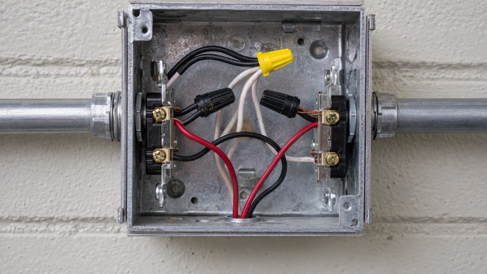
Disconnecting all related ungrounded conductors
Multi-wire branch circuits generally require a means to disconnect all ungrounded conductors at the same time. In practice, that usually means handle ties on adjacent breakers or a common-trip multi-pole breaker where the installation requires it. The exact device depends on the circuit type, protective function, panelboard listing, and local adopted code, so this is one of those details I would not leave to “whatever was in the maintenance crib.”
The safety reason is practical. If a technician opens one breaker on a shared-neutral circuit and assumes the box is dead, the other ungrounded conductor can still energize part of the circuit. Worse, opening a neutral under load can push abnormal voltages onto connected 120 V equipment. Small power supplies, LED drivers, controls, and instrumentation do not tolerate that politely.
Neutral continuity should not depend on a receptacle or device remaining installed. On multi-wire branch circuits, splice the neutral through and use pigtails to devices so removing one receptacle does not open the neutral for downstream loads. I have seen this missed on split-wired receptacles feeding shop benches; the first device gets replaced during a lunch-break repair, the neutral path is interrupted, and the complaint later is “random electronics failures,” not “we opened a shared neutral.”
Grounding path and bonding details
Equipment grounding conductor sizing is based on the overcurrent protection and applicable code tables, not on whether the load is casually called 110 or 220. If multiple circuits share the raceway, grounding conductors and raceway bonding still need to suit the actual protective devices and fault-current path. A smaller control circuit in the same conduit does not make the grounding path optional or generic.
Metal raceways can be part of the equipment grounding path when they are listed and installed correctly, but plant-floor conditions make me cautious. Painted enclosures, loose locknuts, concentric knockouts, corroded fittings, flexible sections, vibration, and oil-soaked washdown areas can all weaken the effective bonding path. Depending on the raceway type and installation, you may need bonding bushings, bonding jumpers, grounding pigtails, listed fittings, or a separate equipment grounding conductor pulled with the circuit conductors.
Items worth checking before closing the boxes:
- Locknuts tight and biting properly, not sitting on heavy paint or powder coat.
- Bonding bushings used where required, especially around service equipment, concentric knockouts, or higher-fault-current locations.
- Flexible metal conduit sections bonded as required and not assumed continuous without verification.
- Grounding pigtails installed to metal boxes, device yokes, and equipment grounding terminals.
- Set-screw or compression fittings matched to the environment, especially in vibration or wet areas.
- Continuity verified after assembly, not merely assumed from the material list.
The trade-off is cost and pulling effort versus fault-path confidence. A separate copper equipment grounding conductor adds fill and cost, and on long runs it can be one more conductor to pull around elbows. In a clean commercial run with properly installed EMT, the raceway path may be entirely acceptable. In a plant with forklifts, coolant mist, and ten years of maintenance modifications, I usually prefer the visible, testable grounding conductor unless fill or specification constraints push the other way.
GFCI, AFCI, and identification problems
GFCI and AFCI devices can complicate shared-neutral installations. A single-pole GFCI breaker monitoring one hot conductor will not behave correctly if part of the return current travels on a shared neutral outside its sensing path. That often shows up as nuisance tripping, but the deeper issue is that the protection device does not match the circuit topology.
For shared-neutral circuits, the protective device may need to monitor all related ungrounded conductors and the shared neutral together, often through a two-pole breaker or manufacturer-approved configuration. AFCI devices have similar sensitivity to how current leaves and returns. Mixing standard breakers, handle ties, two-pole GFCI/AFCI breakers, feed-through receptacle devices, and shared neutrals without a wiring diagram is a good way to lose half a day chasing trips that are not random at all.
Color identification should be treated as part of the engineering, not decoration. Typical practice is:
- Grounded conductors identified white or gray, with field marking only where allowed.
- Equipment grounding conductors identified green, green with yellow stripe, or bare where permitted.
- Ungrounded conductors identified with colors other than those reserved for grounded and grounding conductors.
- High-leg conductors on applicable delta systems identified as required, commonly orange in many NEC-based installations.
- Project-specific conductor schedules showing circuit number, voltage, phase or leg, neutral association, and grounding method.
This section’s guidance holds only after the circuit type is correctly identified at the source. Before buying cable or pulling conductors, confirm the panel system, breaker arrangement, protective device type, neutral sharing plan, grounding method, and color schedule on the drawings and in the field; the conduit can be legal while the conductor relationships inside it are still wrong.
Cases requiring separation
Some wiring should stay out of a shared power conduit even when the nominal voltages look harmless. The usual rejection points are communication circuits, power-limited controls, life-safety systems, sensitive instrumentation, VFD and servo cabling, emergency power systems, and any location where the wiring method approval is more restrictive than the voltage rating alone.
Low-voltage data or control cables may be pulled with 120/240 V power conductors simply because the voltage is lower.False
Voltage level is not the only rule. Circuit class, insulation rating, listing, separation barriers, noise exposure, and the governing installation standard can all require separate raceways or listed assemblies.
Communications, Ethernet, coaxial, and building networks
Power conductors do not belong in the same conduit as Ethernet, coaxial cable, telecom, access-control data, or most building automation network cabling unless a specific listed system and applicable code rule permits that installation. In practice, the inspector, IT contractor, and commissioning engineer will usually reject it before the legal argument gets very far.
The issue is partly electrical safety and partly signal integrity. Category cable, coax, RS-485 building controls, BACnet MS/TP, Modbus RTU, intercom wiring, and telecom pairs are not treated as ordinary branch-circuit conductors. Their jackets and insulation systems are selected for communication circuits, flame rating, plenum or riser use, and signal performance, not for being bundled beside 120 V or 240 V power conductors in a raceway.
A few common plant-floor examples:
- Ethernet to a machine HMI: keep it in its own conduit, wireway compartment, or listed industrial cable routing system. Do not pull it beside motor power because “it is only 24 V data.”
- Coaxial camera cable: separate it from lighting and receptacle circuits, especially in long runs where induced noise creates rolling lines, dropouts, or unexplained recorder faults.
- Building automation trunk cable: avoid sharing conduit with fan motor feeders, VAV box power, or lighting branch circuits unless the cable and system are specifically designed and approved for that arrangement.
- Telecom and intercom wiring: treat as a separate system. Shared power conduit is a maintenance headache even if the installation somehow survives initial testing.
Class 2 and Class 3 control circuits
Class 2 and Class 3 control circuits are often the trap in mixed-conduit discussions. A 24 VDC sensor loop, thermostat cable, door strike control, or PLC input circuit may look physically small and safe, but power-limited circuit rules usually demand separation from power and lighting conductors unless a permitted exception is met.
The key variables are:
- Circuit classification: Class 2 and Class 3 circuits are power-limited by the source and protected under different rules than branch circuits.
- Insulation rating: having insulation rated high enough for the highest voltage present can help in some mixed-control cases, but it does not automatically override power-limited separation rules.
- Barriers and compartments: a listed barrier inside a wireway or control panel can allow power and control conductors to occupy the same enclosure while remaining separated.
- Raceway separation: separate conduit is often the cleanest answer in the field because it avoids debates over insulation, listing, and whether the circuit remains power-limited after routing.
- System listing: some assemblies are evaluated as a complete system. Once you improvise the routing, you may void the installation method the manufacturer intended.
The trade-off is cost versus future certainty. One extra 3/4 in. conduit run feels wasteful during installation, especially above a crowded ceiling or along a congested conveyor line. Six months later, when a technician is chasing intermittent inputs with a meter in one hand and a radio in the other, that separate conduit often looks cheap.
Fire alarm, security, nurse call, and life-safety wiring
Fire alarm, emergency communication, security, nurse call, smoke control, mass notification, and similar circuits often face stricter separation than ordinary controls. The governing installation standard, local amendments, engineering specification, insurer requirements, or authority having jurisdiction may impose rules that go beyond the simple “insulated for the highest voltage” concept.
This is where procurement teams get burned. A cable may be technically good cable, and the conduit may have spare capacity, yet the system supplier refuses commissioning because the routing violates their installation manual or the project specification. On hospitals, schools, high-rise buildings, data centers, tunnels, and industrial sites with emergency shutdown systems, separation is not paperwork; it is part of survivability and fault isolation.
Typical separation drivers include:
- keeping life-safety circuits away from normal power faults;
- preserving operation during fire, flooding, or mechanical damage;
- avoiding common-mode failures where one damaged raceway disables both normal and emergency functions;
- maintaining inspection access and traceability;
- meeting the specific listing of fire alarm or nurse call cable.
If the circuit protects people rather than just equipment uptime, assume separate routing until the responsible standard, designer, and authority having jurisdiction confirm otherwise.
Instrumentation, analog signals, encoders, and sensors
Instrumentation is where code permission and good engineering most often part ways. A 4-20 mA loop might survive in the same tray as power cable for years, or it might produce a drifting tank level every time a 15 hp pump starts. Both outcomes are believable because the problem depends on cable construction, grounding, run length, source impedance, switching noise, and how the shields are terminated.
Keep these circuits out of power conduit unless the design has been checked deliberately:
- 4-20 mA analog loops: usually robust, but long parallel runs with motor feeders can still inject noise or create ground-loop errors.
- Thermocouples: very low signal levels; they dislike electrical noise, poor junction practice, and mixed metals. Running them with branch power is asking for unstable temperature readings.
- RTDs: more stable than thermocouples in many installations, but lead resistance and noise still matter, especially on long runs.
- Encoder wiring: pulse integrity matters. Noise can become false counts, speed ripple, or drive trips.
- Load cells and millivolt sensors: keep them physically and electrically quiet. Shielding practice is not optional.
- Proximity switches and photoeyes: discrete signals tolerate more abuse, but cheap unshielded sensor cable beside a VFD lead will still cause nuisance faults.
The mechanism is straightforward: alternating current and fast switching edges create magnetic and electric fields; long parallel conductors become receivers; imperfect shields and multiple ground points turn the wiring system into part of the circuit. The preferred choice flips only when the signal cable is specifically rated and shielded for the environment, the separation distances are impractical, and testing confirms acceptable noise margin under worst-case machine operation.
VFD output leads, motor feeders, and servo cables
Variable frequency drive output conductors, servo motor cables, and some motor feeders deserve their own raceways or properly designed shielded cable systems. The problem is not just 220 V or 480 V magnitude; it is the waveform. VFDs switch fast, and those fast edges create high-frequency noise, bearing-current concerns, reflected-wave voltage stress on long motor leads, and interference with nearby controls.
Do not put these in the same raceway as:
- analog instrumentation;
- encoder or resolver feedback;
- Ethernet or fieldbus cable;
- Class 2 sensor wiring;
- fire alarm or security circuits;
- PLC input/output wiring unless the control panel design specifically provides segregation.
For VFD installations, follow the drive manufacturer’s cable and grounding instructions. Many drives call for shielded motor cable, symmetrical grounds, proper gland termination, and short bonding paths. A pigtail shield drain landed under a random terminal screw is not the same as a 360-degree shield termination through a proper EMC gland. That detail sounds fussy until the machine faults only during wet weather or when the night shift runs two lines at once.
Emergency, standby, and critical operations power
Emergency systems, legally required standby systems, optional standby systems, and critical operations power systems may require separation for reliability, selective survivability, or maintenance access. This is not always because mixed voltages are electrically incompatible. It is because a single raceway failure should not remove both the normal source and the backup function.
A designer may require separate routing for:
- emergency lighting and normal lighting branch circuits;
- generator start, control, and feeder wiring;
- fire pump power and associated controls;
- transfer switch control wiring;
- critical operations loads in command centers, industrial safety systems, or essential process areas;
- circuits that must remain functional during fire or other abnormal events.
Optional standby systems can be less restrictive than emergency systems, but do not assume. A production plant may treat a freezer, furnace control, wastewater lift station, or process safety PLC as commercially critical even if the electrical code classification is not “emergency.” Downtime risk can justify separate conduit because repair speed and fault isolation matter.
Hazardous, corrosive, wet, and high-temperature locations
In classified industrial zones, washdown rooms, rooftops, tunnels, chemical areas, foundries, and high-temperature process spaces, the wiring method can decide the issue before conductor voltage does. Conduit seals, cable glands, insulation temperature rating, corrosion resistance, jacket material, oil resistance, sunlight resistance, wet-location marking, and hazardous-location approval all become decisive.
Watch for these cases:
- Hazardous locations: use wiring methods approved for the class, division or zone, gas group, dust group, and temperature code. Mixed conduit can complicate sealing and maintenance.
- Corrosive areas: PVC-coated rigid steel, stainless hardware, or nonmetallic raceway may be specified; pulling extra systems through the same path can undermine segregation and identification.
- Wet locations: conductors and cables must be listed for wet use where required. A “dry only” control cable in a wet conduit is not rescued by being low voltage.
- High-temperature areas: ampacity, insulation life, and jacket embrittlement change quickly near ovens, boilers, furnaces, and roof decks.
- Oil and coolant exposure: machine-tool areas often need cable jackets that tolerate cutting fluid, hydraulic oil, and cleaning chemicals.
Separate conduit is sometimes an engineering reliability requirement, not a simple code prohibition. Clean power, low noise, visible routing, spare capacity, lockout clarity, and fast troubleshooting have commercial value. The boundary is that separation should be designed, not guessed: verify the applicable code article, project specification, equipment manuals, cable listings, and site conditions before buying cable or releasing conduit drawings.
Conductor and cable selection
Permitted mixed-voltage conduit only works if the purchased conductors are specified for the highest voltage, the actual environment, and the way they will be pulled and terminated. A code-compliant layout can still become a procurement failure if the insulation, jacket, markings, certifications, or reel lengths do not match the installation method. For industrial buyers, the cable schedule is where the electrical design becomes something the warehouse, electrician, inspector, and maintenance crew can all live with.
Choosing the cable construction
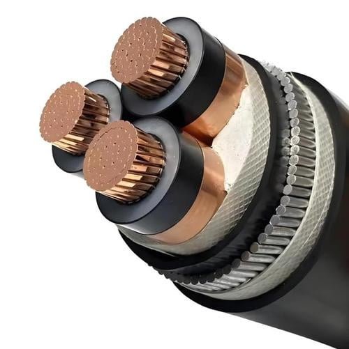
Individual building wire in conduit is common for plant power distribution because it gives the installer flexibility: separate phase, neutral, and grounding conductors can be pulled as needed, replaced individually, and color-coded in a familiar way. That is usually the practical choice for EMT, rigid metal conduit, PVC conduit, or liquidtight runs feeding panels, disconnects, and fixed equipment.
Multi-conductor cable assemblies change the procurement and installation picture. They can reduce pulling confusion and improve repeatability, but they also lock in conductor count, color code, jacket material, bend radius, and termination approach. In a busy plant, that can be a blessing or a nuisance depending on how often the equipment layout changes.
| Cable option | Where it fits | Procurement watch points |
|---|---|---|
| Individual building wire in conduit | Branch circuits, feeders, panel-to-machine runs | Voltage rating, insulation type, color, reel length, pulling lubricant compatibility |
| Multi-conductor power cable | Skid wiring, packaged equipment, short machine feeders | Overall jacket rating, conductor identification, bend radius, gland compatibility |
| Tray cable | Cable tray, industrial control and power distribution where allowed | Listing/standard, sunlight rating, wet rating, crush and flame performance |
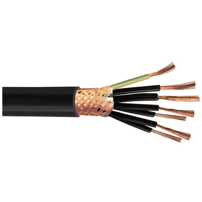
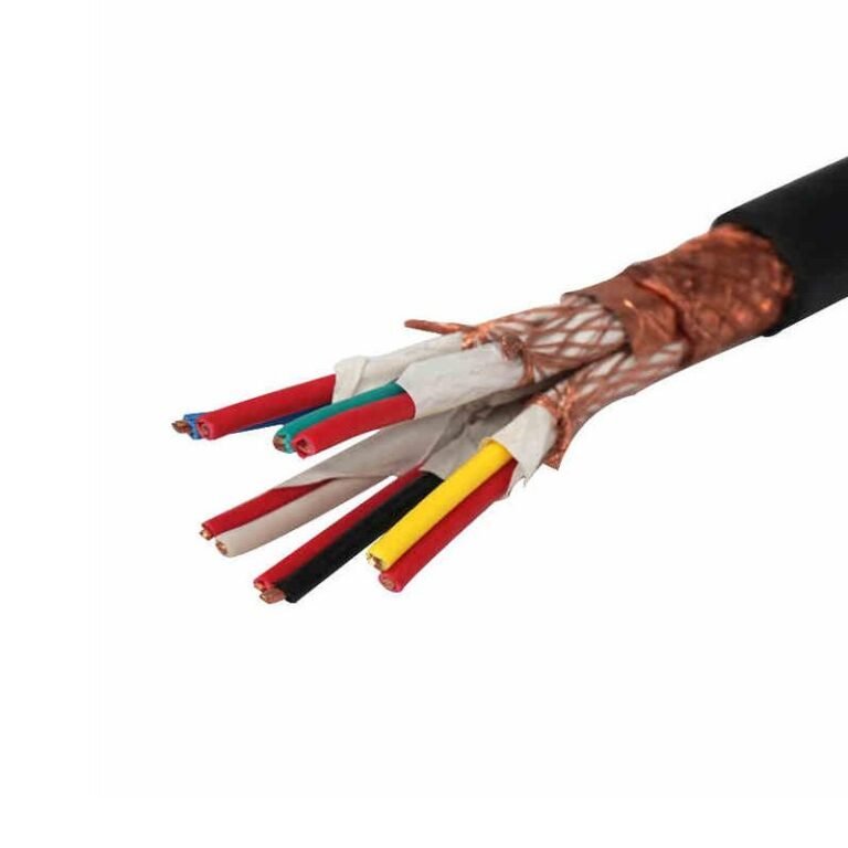
| Control cable | PLC I/O, instrumentation, interlocks, low-current controls | Shielding, numbered cores, noise separation, jacket chemical resistance |
| Flexible cable | Moving equipment, portable machines, vibration-prone connections | Flexing class, oil resistance, abrasion resistance, strain relief |
| Equipment cable assemblies | OEM machinery, modular skids, plug-connected systems | Connector pinout, certification scope, replacement availability |
A frequent mistake is buying “600 V cable” as if that answers every question. It does not. The buyer still has to define:
- Copper or aluminum conductor.
- Conductor size, including any upsizing for voltage drop or derating.
- Stranding class, especially for tight bends, vibration, or flexing.
- Temperature rating, such as 60°C, 75°C, or 90°C insulation, matched to terminal ratings.
- Voltage rating for every conductor in the shared raceway.
- Insulation type and applicable standard.
- Jacket material, if using cable rather than single conductors.
- Flame rating required by the installation location.
- Oil resistance for machine areas, hydraulic units, presses, and machining cells.
- Sunlight resistance for rooftop, outdoor tray, or exposed yard runs.
- Wet-location suitability for underground conduit, washdown zones, condensation-prone runs, or outdoor junction boxes.
Insulation and jacket compatibility in shared raceways
Insulation compatibility matters because conductors in one conduit share heat, mechanical rubbing, pulling lubricant, and any liquid or vapor that enters the raceway. Nylon-jacketed thermoplastic building wire may be perfectly normal in dry commercial conduit, while XLPE-insulated cable may give better heat and moisture performance in heavier industrial work. PVC jackets are widely used and economical, but chemical exposure, low-temperature handling, and flame-smoke requirements can change the decision quickly.
In practice, the raceway is rarely as clean as the drawing. I have opened conduits with cutting oil residue, water from a failed seal, fine cement dust, and the occasional mystery fluid nobody wants to identify. Oil-resistant compounds are not decoration in those areas; they slow jacket softening, swelling, and cracking when cables sit near coolant sumps, hydraulic power units, or oily machine bases. LSZH materials can be requested for certain enclosed public, tunnel, transit, or low-smoke projects, but they should not be treated as a universal upgrade because flexibility, cost, and regional certification requirements may differ.
For circuits rated 1000 V or less, the main shared-raceway insulation rule is that every conductor must be insulated for the maximum voltage present.True
This reflects the NEC 300.3(C)(1) principle, but the final installation still has to satisfy all other applicable code, listing, derating, fill, and project requirements.
The trade-off is simple: a tougher insulation and jacket system can tolerate heat, oil, sunlight, or abrasion better, but it may be larger, stiffer, more expensive, and harder to pull through crowded conduit. The preference flips when the run is short, dry, protected, and easy to replace; then a standard listed building wire may be the sensible purchase. That conclusion stops holding when the conduit is outdoors, wet, chemically exposed, routed through machinery, or expected to operate for years without convenient shutdown access.
Identification and documentation for bulk procurement
Mixed 110 and 220 circuits fail fastest when nobody can identify them after the original electrician leaves. For bulk orders, conductor identification should be agreed before production or shipment, not improvised with whatever tape is in the gang box.
Useful identification options include:
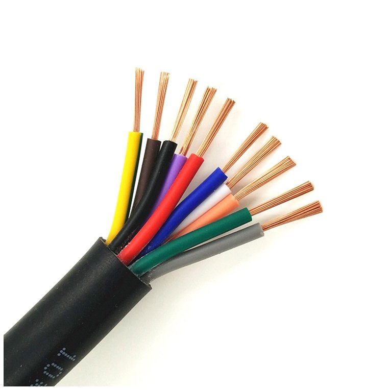
- Standard insulation colors for phase, neutral, and equipment grounding conductors where local code and plant standards allow.
- Numbered cores for control cables and multi-conductor assemblies.
- Printed legends showing circuit number, voltage class, panel reference, or project code.
- Stripe marking when multiple similar colors are needed.
- Phase tape at terminations, especially for larger conductors where full-color insulation may not be used.
- Heat-shrink markers for panels, motors, disconnects, and junction boxes.
- Custom cable schedules tying reel numbers to areas, equipment tags, and installation drawings.
For international projects, documentation can matter as much as the cable itself. Buyers should state which approvals or declarations are required instead of assuming one mark covers every country. Depending on the destination and use, the package may need UL or CSA listings, IEC-based construction references, CE-related documentation where applicable, CPR classification for relevant European construction applications, RoHS and REACH declarations, factory test reports, and material traceability records. The exact requirement should be checked against the installation country, project specification, and authority having jurisdiction; a supplier cannot responsibly guess that from “industrial cable” alone.
Installation details that belong on the purchase order
Cable procurement should include the way the product will be installed. A conductor that looks correct on paper may be miserable to pull through four 90-degree bends in old rigid conduit with a burr at the coupling. That is not a cable-quality issue; it is a specification gap.
Put these details in the inquiry package:
- Conduit type and size.
- Pull length and number of bends.
- Minimum bend radius available at panels and pull boxes.
- Expected pulling tension and pulling method.
- Ambient and installation temperature.
- Indoor, outdoor, wet, oily, UV, washdown, or chemical exposure.
- Termination hardware, lugs, glands, connectors, and terminal temperature rating.
- Required spare capacity for future conductors or replacement pulls.
- Packaging preference, including reel size, cut length, labeling, and delivery sequence.
A practical procurement checklist for mixed-voltage conduit work should include:
- Voltage rating.
- Conductor material and size.
- Insulation standard and insulation type.
- Temperature rating.
- Flame performance requirement.
- Oil, sunlight, wet-location, or chemical-resistance requirement.
- Required certification or documentation package.
- Conductor or core marking method.
- Packaging length and reel identification.
- Factory test report requirement.
- Delivery schedule and batch traceability.
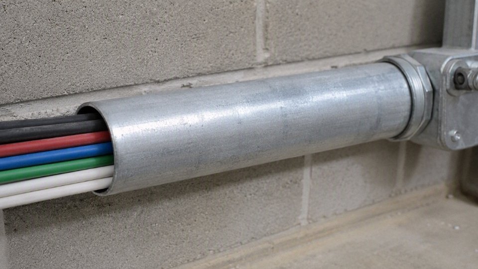
Shandong Jinda Special Cable Group can support project-specific conductor and cable specifications, bulk supply, quality documentation, technical coordination, and repeat procurement programs for industrial installations. The most useful inquiry is not just a conductor size list; it includes the circuit schedule, installation environment, required standards, marking method, packaging plan, and delivery sequence so the supplied cable matches the plant work rather than only the drawing.
Installation and inspection checkpoints
- Build a circuit inventory before touching conductor counts.
List every circuit planned or found in the raceway, not just “110” and “220.” For each one, record:- Nominal voltage and phase arrangement
- Source panel or disconnect
- Breaker or fuse size
- Load type: motor, receptacle, heater, lighting, controls, VFD-fed load, HVAC, welder, kitchen equipment
- Whether the load needs a neutral
- Equipment grounding method
- Whether any circuit is a multi-wire branch circuit
- Whether the circuit is continuous load or intermittent load
This sounds basic, but it catches a lot of bad installations. I have seen conduits labeled as “power feed” where one raceway contained a receptacle circuit, a heater circuit, and a control transformer primary, all from different panels. That is not something to approve from a conduit-fill calculation alone.
- Verify insulation ratings and conductor markings at accessible points.
Check the printed markings on the conductors at panels, junction boxes, pull boxes, wireways, and equipment terminations. Confirm that every conductor insulation rating is suitable for:- The highest voltage present in the raceway
- Wet or dry location conditions
- Ambient temperature around the conduit
- Terminal temperature limits, usually 60°C or 75°C depending on equipment
- Oil, sunlight, chemical exposure, or outdoor use where applicable
For circuits rated 1000 V or less, NEC 300.3(C)(1) generally permits conductors of different systems in the same raceway only when every conductor has insulation rated for the maximum voltage present.True
This is the main code concept behind mixing nominal 110 V and 220 V conductors, but the installation still has to satisfy fill, ampacity, grounding, box, identification, and equipment rules.
Do not assume insulation from color. A white conductor can be THHN/THWN-2, MTW, fixture wire, or something else entirely depending on where it came from. If the marking is missing, damaged, or not traceable, treat it as an inspection problem, not a guessing game.
Calculate conduit fill with actual dimensions, not “it looks roomy.”
Use the raceway type and trade size, then apply the actual outside diameter or published area of each conductor or cable. Include all conductors in the raceway, and account for:- Conduit body limitations
- Oversized insulation types
- Compact versus standard stranded conductors
- Existing abandoned conductors that should be removed or counted
- Planned spare conductors
- Future expansion, if the project owner expects it
The usual NEC Chapter 9 benchmark for more than two conductors is 40% maximum fill, but fittings and pull geometry matter in the field. A raceway can pass fill on paper and still be a miserable pull if it has tight LB fittings, too many bends, or conductors with scuffed insulation from an earlier pull.
Perform ampacity adjustment before approving breaker sizes.
Count current-carrying conductors correctly. Grounds do not normally count. Neutrals may or may not count depending on the circuit type and harmonic content. Then evaluate:- Number of current-carrying conductors in the raceway
- Ambient temperature around the installation
- Rooftop, boiler room, ceiling plenum, or outdoor exposure
- Terminal temperature rating
- Continuous-load sizing
- Conductor material and insulation temperature rating
- Whether harmonic-producing loads are present
More than three current-carrying conductors in a raceway usually triggers ampacity adjustment under NEC 310.15. This is where a legally shareable conduit often becomes commercially unattractive: larger conductors, a larger raceway, or separated runs may cost less than fighting derating. The preferred choice flips when labor access is poor or shutdown windows are short; then a single properly upsized raceway may still beat multiple new runs.
Confirm that circuit conductors stay together.
Each circuit’s ungrounded conductors, neutral if used, and equipment grounding conductor path must be properly routed and identifiable. Check for:- Split neutrals between conduits
- Shared neutrals without proper multi-wire branch circuit handling
- Missing handle ties or common-trip breakers where required
- Neutral conductors borrowed from another circuit
- Grounds used as neutrals, which should stop the inspection immediately
- Incorrect re-identification of grounded conductors
Keeping conductors together is not just neat workmanship. It controls inductive heating, fault return paths, voltage stability, and troubleshooting safety. A split circuit may work with a tester and still create heat in metal raceway or confuse the next maintenance electrician at 2 a.m.
Open and inspect every junction box and pull point.
Do not approve a same-conduit installation from panel ends only. Boxes and pull points often reveal the actual condition of the job:- Box fill and conductor crowding
- Splice connector type and rating
- Loose wire nuts, split bolts, or compression connectors
- Burn marks, nicked copper, flattened insulation, or overheated tape
- Minimum free conductor length
- Barriers where required by equipment design or voltage class
- Circuit labels on conductors and covers
- Covers installed and accessible, not buried above hard ceiling or behind equipment
If a box is packed so tightly that conductors spring out when the cover is removed, expect heat, damaged insulation, and maintenance errors later.
Review protective devices and operating procedures.
Check the breaker or fuse type against the load and wiring method. Include:- Common trip or handle tie requirements
- GFCI compatibility, especially with shared neutrals or leakage-producing equipment
- AFCI requirements where applicable
- Short-circuit current rating of panels and equipment
- Selective coordination requirements for critical systems
- Lockout points and whether all sources are obvious to maintenance staff
- Panel directory accuracy
Mixed-voltage raceways make labeling and lockout more important. A mechanic may shut off the 220 V breaker feeding a small machine and still have a 110 V receptacle circuit live in the same junction box.
Inspect the physical installation like a puller, not just like a plan reviewer.
Look for:- Bushings or insulated throat fittings at metal raceway entries
- Grounding continuity across couplings, locknuts, flex, and bonding jumpers
- Pulling damage at bends and conduit bodies
- Abrasion where conductors enter cabinets
- Raceway support spacing and loose straps
- Excessive bend count between pull points
- Expansion fittings across building joints or long outdoor runs
- Wet-location sealing, drain paths, and corrosion protection
- Mixed metals, damaged galvanizing, or water sitting in low conduit runs
- Document the installation before energizing or releasing procurement.
The final package should include:- Updated panel schedules
- As-built conduit routing
- Conductor schedule with size, insulation type, color, and circuit ID
- Raceway size and fill calculation
- Ampacity adjustment calculation
- Test results, such as continuity, insulation resistance where appropriate, and grounding checks
- Photos of representative junction boxes before covers are installed
- Maintenance notes for lockout, spare conductors, and future expansion limits
The inspection boundary is simple: if conductor identity, insulation rating, circuit grouping, derating, or source control cannot be verified, the installation is not ready for energizing or procurement approval. Guessing may save one site visit, but it transfers the risk to startup, maintenance, and whoever has to troubleshoot the system after production is waiting.
Frequently asked questions
Can 120 V and 240 V wires be in the same conduit?
Yes, in many building-power installations they can share the same conduit if the conductors are part of systems rated 1000 V or less and every conductor insulation is rated for the highest voltage present. The installation still has to pass conduit fill, ampacity derating, grounding, and local inspection requirements.
Can I run a 220 V dryer circuit and a 110 V outlet circuit in the same pipe?
Often yes, but I would check it carefully before pulling wire. A dryer circuit may have two hots, a neutral, and an equipment grounding conductor, while the receptacle circuit may add another hot and neutral. That can push the raceway into derating and fill issues quickly, especially in smaller EMT or PVC.
Do all wires in the conduit need to be rated 600 V?
Not always by that exact number, but in common North American practice most building wire used for 120 V and 240 V branch circuits, such as THHN/THWN-2, is commonly marked 600 V. The key rule is that every conductor must be insulated for at least the maximum voltage present in that raceway.
Can I put low-voltage thermostat or Ethernet cable in the same conduit as 120 V or 240 V power?
Usually no, unless the specific cable, insulation system, and installation method are permitted for that use. Standard thermostat wire, control cable, data cable, and Ethernet cable are normally kept separate from power wiring. Noise is one concern, but the bigger issue is insulation rating and code classification.
Does a neutral count as a current-carrying conductor for derating?
Sometimes. A neutral that only carries the unbalanced current of a properly configured multi-wire branch circuit may be treated differently from a neutral that carries full load or harmonic current. In plants with electronic power supplies, LED drivers, VFD-related loads, or office IT loads, do not assume the neutral is thermally insignificant.
Can two circuits share one ground wire in the same conduit?
Yes, multiple circuits in the same raceway can often share one equipment grounding conductor if it is sized for the largest overcurrent device involved and installed correctly. Metal conduit may also serve as the equipment grounding path where permitted, but many buyers still specify a copper ground for reliability and inspection comfort.
Can two circuits share one neutral?
Only in specific arrangements, such as a properly wired multi-wire branch circuit with conductors on different phases or legs and the required common disconnecting means. Randomly tying two branch circuits to one neutral is a bad service-call generator: overloaded neutrals, nuisance trips, and energized “off” circuits are common outcomes.
Do I need a two-pole breaker if 120 V and 240 V circuits share conduit?
Sharing conduit alone does not automatically require a two-pole breaker. The breaker requirement depends on whether the conductors form a multi-wire branch circuit, share a neutral, supply the same device, or must be disconnected together by code or equipment instructions. If the neutral is shared, expect handle ties or common-trip protection to be required.
Is metal conduit safer than PVC for mixed-voltage circuits?
Metal conduit gives better mechanical protection and can provide an equipment grounding path when installed with tight, listed fittings. PVC avoids corrosion and is common in wet or underground work, but it offers no metallic shielding or grounding path. “Safer” depends on impact exposure, moisture, grounding design, installation workmanship, and the authority having jurisdiction.
Will running 110 and 220 together cause electrical interference?
For ordinary 120 V and 240 V power circuits, interference is usually not the main problem. The bigger risks are heat, fill, and incorrect neutral or breaker relationships. Interference becomes more relevant when the conduit includes sensitive controls, instrumentation, communication cable, VFD output leads, or long parallel runs near low-level signals.
Can I add more wires to an existing conduit?
Maybe, but do not judge by whether the fish tape still goes through. Check the conduit size, existing conductor insulation, number of current-carrying conductors, bends, pull distance, spare capacity, and derating. Older raceways often have unknown splices, damaged insulation, or mixed conductor types that make “just add two wires” a poor maintenance shortcut.
Should I use cable or individual conductors inside conduit?
For most conduit runs, individual listed conductors are cleaner to pull, easier to derate, and easier to terminate. Cable assemblies inside conduit can be legal in some cases, but they are bulkier and often make fill calculations worse. In industrial procurement, individual conductors also simplify color coding, drum planning, and replacement after a fault.
Verify your conduit plan
Use this final pass before you approve drawings, release a purchase order, or let an electrician pull wire. A shared conduit for 110 and 220 circuits is often workable, but it is only a “yes” after the whole wiring system checks out: voltage rating, circuit grouping, derating, fill, grounding, protection, separation rules, and the local authority’s approval.
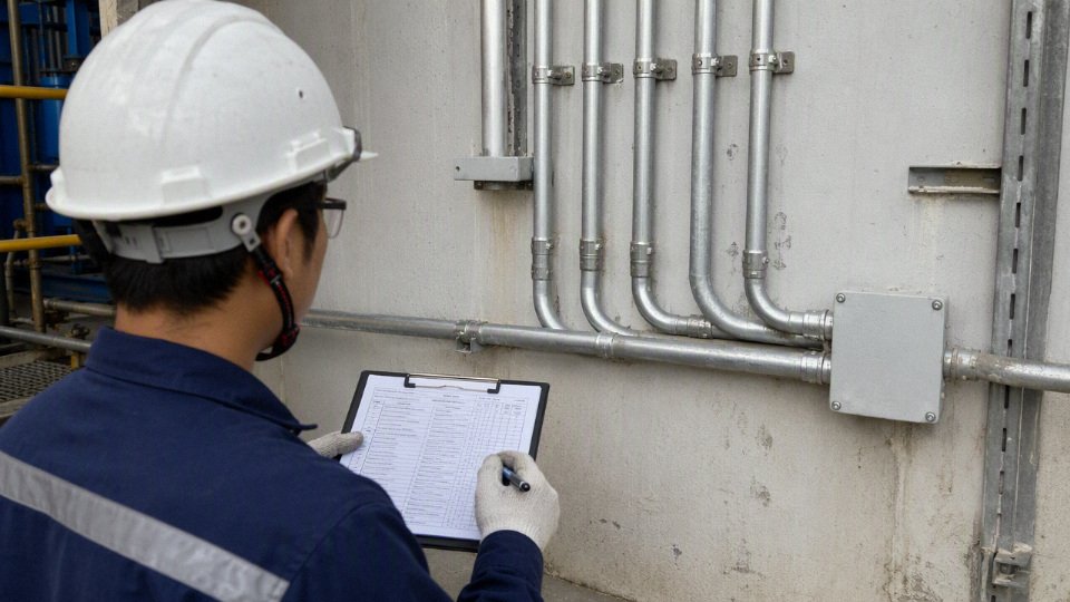
Final go/no-go checklist
- Conductor insulation voltage rating: every conductor in the raceway must be rated for the highest voltage present, not just its own circuit voltage.
- Circuit conductors kept together: phase, neutral where used, and equipment grounding conductors must be routed so the circuit is complete and traceable. Do not scatter related conductors across different conduits to “make room.”
- Current-carrying conductor count checked: count the conductors that actually carry load current and apply ampacity adjustment where required. Shared conduit that looked neat on the drawing can run too warm once derating is applied.
- Conduit fill confirmed: check the actual conductor outside diameters against the raceway size. For more than two conductors, 40% fill is a common NEC Chapter 9 reference point, but the exact calculation depends on the raceway and conductor type.
- Neutrals verified: shared neutrals, multi-wire branch circuits, and separately derived systems need careful review. A neutral that is “available in the pipe” is not automatically the correct neutral.
- Grounding path continuous: equipment grounding conductors, metallic raceway continuity, bonding bushings, and terminations all need to match the installation method.
- Protective devices compatible: breaker ratings, common disconnecting means where required, handle ties, GFCI/AFCI behavior, and fault-current ratings should be checked before procurement locks in panel hardware.
- No prohibited mixed systems: do not include control, communication, data, fire alarm, instrumentation, or other low-voltage signal circuits unless the applicable rules and equipment listings clearly allow that arrangement.
- Local approval path clear: project specifications, utility rules, insurance requirements, and the authority having jurisdiction can be stricter than the base code text.
110 V and 220 V conductors can often be installed in the same conduit when all conductors are insulated for the maximum voltage present and the installation satisfies fill, ampacity, grounding, grouping, and separation requirements.True
This reflects the general NEC approach for circuits rated 1000 V or less, but the final decision still depends on the complete installation and local approval.
Separate the circuits when the calculation is marginal. That is usually the better plant-floor choice if the conduit is already near fill, derating forces an upsized conductor, future spare capacity matters, or maintenance crews will need to isolate circuits quickly during a night shift. I also lean toward separation where VFD output conductors, sensitive instrumentation, long parallel runs, or strict project specifications are involved; the extra conduit can be cheaper than nuisance trips, noise complaints, or a failed inspection.
For procurement, freeze the cable and conductor specification before bulk ordering. At minimum, confirm:
- conductor material and size;
- insulation type and voltage rating;
- applicable certification or standard marking;
- color coding and identification method;
- print legend requirements;
- packaging length, reel type, and pulling direction;
- test documents and inspection records required by the buyer;
- delivery schedule matched to site installation windows.
If you need cable selection support or a bulk quotation, send Jinda the conduit schedule, circuit list, voltage ratings, load current, project standards, installation environment, required certifications, and any preferred color or marking rules. Clear drawings or marked-up panel schedules help avoid the usual buying mistake: ordering compliant cable that does not quite fit the conduit, derating calculation, or site identification practice.
The right answer is not simply whether 110 and 220 can share conduit. The right answer is whether the complete wiring system remains code-compliant, thermally sound, maintainable, inspectable, and ready to buy without rework after the cable is already on the reel.