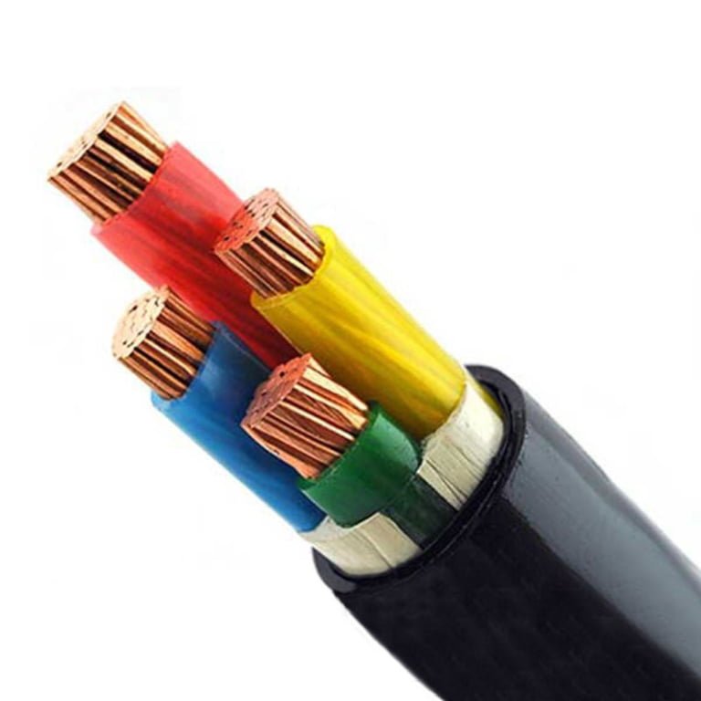
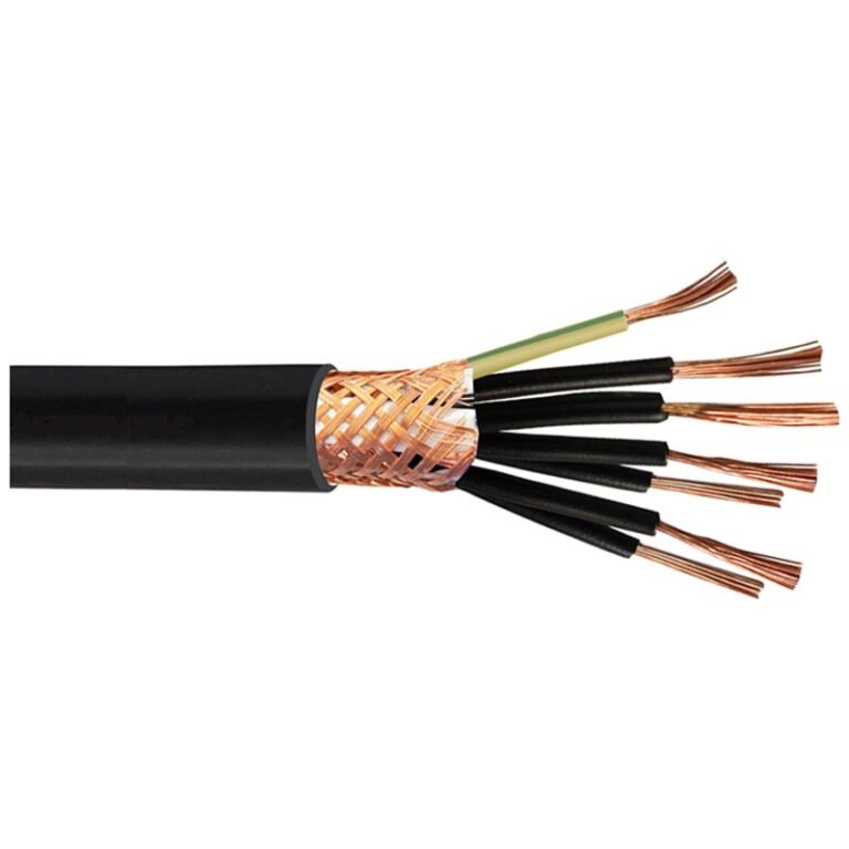
A 24 V sensor cable laid beside a motor feeder may look tidy on the drawing, but on the plant floor it can turn into nuisance faults, failed inspections, or insulation-risk arguments nobody budgeted time for. False PLC inputs stop equipment, electricians start tracing ghosts, and a cheap tray decision becomes overtime, scrap, and rework. The right answer is usually separation, a listed barrier, or cable selected and installed for the highest voltage in the shared space.
Usually, you should not run low-voltage control or signal wire in the same conduit, tray space, or enclosure section as higher-voltage power conductors unless the installation method is specifically permitted: physical separation, a listed barrier, a divided tray, or insulation rated and approved for the highest voltage present. Always verify the applicable electrical code and cable listing.
The awkward part is that “low voltage” means different things to a controls engineer, a building inspector, and a purchasing team ordering cable by reel price. A 24 VDC proximity switch lead, a 120 VAC control circuit, and a 600 V-rated tray cable can all sit in different rule buckets, and the safe choice depends on insulation rating, circuit class, enclosure layout, noise sensitivity, and the standard being enforced on that site.
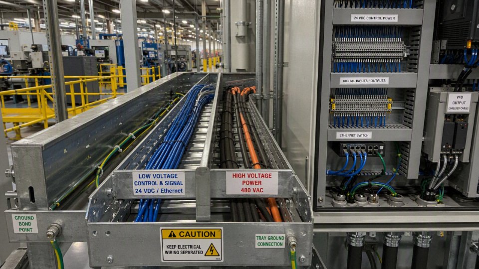
Voltage terms and circuit classes
“Low voltage” is not a single engineering category, and that is where many bad mixed-wiring decisions start. A 24 VDC sensor loop, an Ethernet cable, a 120 VAC branch circuit, and a 480 VAC motor feeder may all be called “low” by someone on site, but codes and standards do not treat them as interchangeable conductors with different numbers printed on the jacket.
In plant speech, “high voltage” often means whatever the electrician does not want routed with controls: 480 V motor power in North America, 400 V three-phase in many IEC plants, or 600 V distribution in some facilities. Utility engineers and IEC terminology may reserve “high voltage” for much higher levels. That language gap matters because a maintenance planner may say “keep the low voltage away from high voltage” while meaning “keep 24 VDC I/O and Ethernet away from 480 V variable-frequency-drive output cable.” Those are not the same problem as utility high-voltage design, but they are still very real safety, noise, and compliance problems inside a factory.
A cable printed 600 V is automatically allowed to share a raceway with any 600 V or lower circuit.False
The voltage marking tells you the insulation rating under that cable standard; mixed installation also depends on circuit classification, listing, separation rules, enclosure barriers, and the applicable electrical code or product standard.
North American practice usually separates wiring by circuit type before it worries about the casual voltage label. The exact article and rule set depend on the adopted edition of the NEC, CEC, or local electrical code, but these categories are commonly encountered:
- Power and lighting circuits: branch circuits and feeders for receptacles, lighting, heaters, motors, drives, and similar loads. A 120 VAC receptacle circuit, 277 VAC lighting circuit, 480 VAC motor feeder, or 600 V distribution run belongs here in typical industrial language.
- Class 1 control and signaling circuits: often used for industrial control where the circuit is not treated as power-limited in the same way as Class 2 or Class 3. A 120 VAC control transformer secondary feeding contactor coils is a common example in older motor-control panels.
- Class 2 circuits: power-limited circuits frequently used for 24 VDC sensors, small control devices, thermostats, access control, and many PLC input circuits when supplied by a listed Class 2 source. The power limitation is as important as the voltage.
- Class 3 circuits: also power-limited, but with different shock and installation considerations than Class 2. These show up less often on a normal machine skid than Class 2, but buyers should not lump them together without checking the product documentation.
- Communications circuits: Ethernet, telephone, data, networked controls, and similar circuits. Category cable in a tray beside motor leads is a common source of nuisance faults, even before the code question is settled.
- Fire alarm circuits: power-limited fire alarm and non-power-limited fire alarm circuits have their own installation logic. Treating fire alarm cable as “just another 24 V pair” is a good way to fail an inspection.
- Instrumentation circuits: 4-20 mA loops, RTD wiring, thermocouples, load cells, pulse signals, encoder feedback, and analyzer signals. Some are electrically rugged; others are millivolt-level circuits that punish sloppy routing with drifting readings and phantom faults.
IEC-based practice uses a different vocabulary, and procurement teams get into trouble when they translate terms too loosely between project documents. Under common IEC usage, low-voltage power systems may include AC systems up to around 1000 V and DC systems up to around 1500 V, depending on the specific standard being applied. Extra-low voltage sits below that, but even extra-low voltage is split by protection method and fault assumptions.
Useful IEC-style concepts include:
- SELV, or safety extra-low voltage: separated from higher-voltage systems by protective separation, intended to reduce shock risk under normal and single-fault conditions.
- PELV, or protective extra-low voltage: extra-low voltage with protective earthing allowed or required in the system design.
- FELV, or functional extra-low voltage: extra-low voltage used for function, but without the same protective separation assumptions as SELV or PELV. This is an easy one to misunderstand; the voltage is low, but the installation may need treatment closer to the source circuit.
- Low-voltage power circuits: the ordinary distribution and utilization circuits feeding motors, panels, heaters, power supplies, and lighting.
- Control circuits: circuits used for machine command, interlocking, indication, and automation. Their treatment depends on source, voltage, energy limitation, insulation, and panel standard.
- Instrumentation and communications circuits: signal integrity and electromagnetic compatibility often drive routing even when shock risk is modest.
The safest first move is to name the circuit by function and classification, not by the loose phrase “low voltage.” For example, a 24 VDC PLC input from a listed Class 2 power supply is not the same design problem as a 24 VDC solenoid output fed by a larger non-power-limited supply. Both may use similar wire colors in a panel, and both may land on terminal blocks two inches apart, but the allowable wiring methods and the consequences of a fault can differ.
Control wiring is confusing because industrial panels mix several worlds in one enclosure. A typical machine panel may have:
- 480 VAC or 400 VAC incoming power.
- A control transformer with 120 VAC or 230 VAC secondary circuits.
- A 24 VDC power supply feeding PLC inputs, proximity sensors, and pilot devices.
- Ethernet or fieldbus cable going to remote I/O.
- Analog instrumentation cable from pressure transmitters, load cells, or temperature devices.
- Safety circuits for emergency stops, guard switches, and safety relays.
The mechanism behind the separation rules is not academic. If a higher-energy conductor faults into a power-limited signal cable, the smaller cable insulation, connector, or device terminal may not be able to clear the fault safely. If a VFD output cable runs tight against an unshielded encoder cable, capacitive and inductive coupling can inject noise into the feedback signal; the drive may trip, the axis may hunt, or the machine may produce scrap that looks like an alignment problem. I have seen maintenance crews chase “bad sensors” for a week when the actual defect was a tray route changed during a weekend installation.
The trade-off is space, cost, and maintainability. Dedicated conduit, divided tray, listed barriers, and separate enclosure compartments cost money and consume panel real estate, but they reduce inspection risk and nuisance troubleshooting. Combining circuits can be acceptable in some systems when all conductors are rated for the highest voltage present and the circuit types are permitted to occupy the same wiring method, but that permission is not created by insulation rating alone. The preferred choice flips when the signal is sensitive, safety-related, fire-alarm-related, communications-based, intrinsically safe, or governed by a listing that demands separation.
For any mixed wiring decision, document these items before choosing conduit, tray, cable, or panel layout:
- Circuit function: power, lighting, control, safety, communication, fire alarm, instrumentation, or hazardous-area signal.
- Maximum voltage to ground: not just line-to-line voltage or nominal supply voltage.
- Energy limitation: Class 2, Class 3, power-limited fire alarm, non-power-limited, current-limited supply, fused branch, or unrestricted feeder.
- Cable insulation rating: commonly 300 V, 600 V, or 1000 V for building and industrial cables, depending on cable type and governing standard.
- Cable listing or approval: tray cable, machine tool wire, communications cable, fire alarm cable, instrumentation cable, flexible cord, or another recognized type.
- Installation rule set: current NEC, CEC, IEC-based wiring rules, machine standard, fire alarm code, hazardous-area standard, customer specification, or local authority requirement.
- Noise sensitivity and operating risk: analog accuracy, encoder reliability, network uptime, safety function integrity, and the downtime cost of intermittent faults.
This section’s conclusion stops holding where a specific code article, product listing, machine standard, or authority having jurisdiction gives a stricter instruction. In practice, start with the circuit class, then verify the cable marking and separation method against the applicable rule set; that sequence prevents the common mistake of letting a 600 V jacket marking answer a question it was never meant to answer.
Code rules that control separation
Code decisions on mixed-voltage wiring start with two questions: what type of circuit is it, and what rule set has jurisdiction over that installation. In NEC-style work, insulation rated for the highest voltage present is necessary in some shared-raceway cases, but it is not enough for many power-limited, communications, fire alarm, and life-safety circuits.
If every conductor is rated 600 V, low-voltage and power wiring can always share a conduit.False
NEC Article 300.3(C) may allow mixed voltages in some cases when insulation is suitable for the maximum voltage present, but power-limited, communications, fire alarm, and other special circuits are controlled by their own articles and may require separation, barriers, or specific listed cable assemblies.
NEC Article 300.3(C) is the starting point, not the whole answer
For many contractors in North America, NEC Article 300.3(C) is the first place to look because it addresses conductors of different systems in the same raceway, cable, box, enclosure, or similar wiring space. The practical logic is simple: if conductors are close enough that a fault or insulation failure can put one circuit onto another, the insulation system must be suitable for the maximum voltage that could be present.
That is why, in ordinary building and industrial wiring, you may see different voltages routed together where permitted and where every conductor insulation rating is high enough. Typical building wire insulation ratings include 300 V, 600 V, and 1000 V depending on cable type and standard. Common industrial control voltages such as 24 VDC, 48 VDC, 120 VAC, and 230 VAC can look harmless compared with feeder voltage, but the code question is not “what is the nominal control voltage?” It is “what voltage could this conductor be exposed to in that wiring method?”
The trap is that Article 300.3(C) does not override all the special articles. A 24 VDC sensor circuit in a machine cabinet, a Class 2 thermostat cable above a ceiling, an Ethernet cable in a tray, and a fire alarm circuit in a hospital corridor may all be “low voltage” in shop-floor language, but they are not regulated the same way.
Common separation methods used when sharing is not allowed or not worth the argument include:
- Dedicated conduit for power and separate conduit for control or signal wiring.
- Divided cable tray with an approved separator.
- Listed barrier inside a wireway, box, panel, or auxiliary gutter.
- Separate enclosure compartments, especially in motor control centers and PLC cabinets.
- Cable assemblies specifically rated and permitted for the highest circuit voltage and application.
- Routing separation by tray tier, wall side, or structural bay where the project specification calls it out.
In practice, I prefer physical separation unless there is a strong reason not to: short runs, crowded risers, prefabricated equipment, or a listed assembly that was designed for mixed circuits. A few extra meters of conduit is usually cheaper than a failed inspection, nuisance analog noise, or having to explain to maintenance why a 24 VDC terminal strip is sitting in the same pull box as a 480 V motor branch circuit.
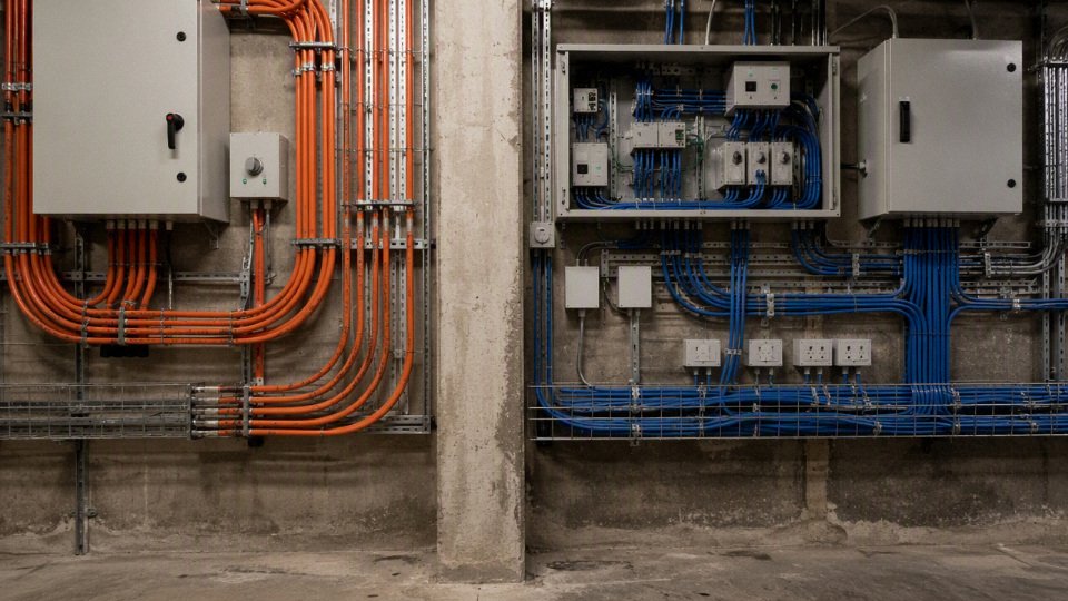
Class 1, Class 2, and Class 3 circuits under Article 725
Article 725 is where many mixed-wiring mistakes happen because it covers remote-control, signaling, and power-limited circuits. This is the territory of control transformers, relay circuits, PLC I/O, solenoid controls, thermostats, access devices, interlocks, and similar wiring. The voltage may be familiar, but the class of circuit changes the wiring permissions.
A useful field distinction is this:
| Circuit type | Typical plant example | Separation issue |
|---|---|---|
| Class 1 | Higher-energy control circuit, motor control circuit, some 120 VAC control wiring | Often treated more like power/control wiring, but insulation and article-specific rules still matter |
| Class 2 | 24 VDC sensors, small control devices, many limited-power supplies | Usually requires separation from power conductors unless specific conditions are met |
| Class 3 | Higher-voltage or higher-power signaling within limits | Also subject to separation rules, with shock protection concerns greater than Class 2 |
The mechanism behind the rule is energy limitation. A Class 2 circuit is intentionally limited so that shock and fire risk are reduced. If it is run together with higher-energy power conductors without proper separation, a fault can defeat that safety basis. A nicked insulation jacket in a crowded box, a loose wirenut, a crushed cable at a tray drop, or a mis-landed conductor during a Friday shutdown can put power voltage onto a circuit that was never intended to carry it.
That is also why “it worked when we tested it” is a poor compliance argument. The code is not only addressing normal operation. It is addressing abnormal contact, maintenance errors, insulation breakdown, and the next technician who opens the cover five years later after three panel modifications and two undocumented sensor additions.
Article 725 contains conditions where proximity may be allowed, such as use of barriers, associated circuits, specific cable constructions, or all conductors insulated for the maximum voltage where the article permits that approach. The exact permission depends on the adopted NEC edition and the circuit details, so the safe procurement question is not just “Is this cable 600 V rated?” It is:
- Is the circuit Class 1, Class 2, or Class 3?
- Is the power supply listed for that class?
- Are the conductors in a raceway, cable tray, enclosure, cable assembly, or open wiring space?
- Is there a listed barrier or divider?
- Are the circuits functionally associated, or merely sharing space because the route is convenient?
- Does the project specification impose stricter separation than NEC minimums?
For power-limited circuits, the preferred choice often flips from “share the route if insulation is adequate” to “separate unless a specific rule permits sharing.” That boundary matters: if the low-voltage circuit is not power-limited and is installed as Class 1 control wiring, the separation analysis may be different.
Communications, data, coaxial, and network cabling
Communications wiring is normally treated more strictly than ordinary control wiring because safety and performance both push toward separation. NEC Article 800 covers communications circuits, while related articles apply to optical fiber, coaxial cable, network-powered broadband, and similar systems. The exact article depends on the cable and service type, not just the connector on the end.
From a plant-floor viewpoint, this is where a neat-looking installation can still be wrong. Running Ethernet, RS-485, coaxial camera cable, or telephone cable in the same conduit as power wiring may save a route, but it creates two problems:
- Electrical safety exposure if power conductors fault into communications cabling.
- Signal quality problems from electromagnetic coupling, especially near motor leads, VFD output cables, contactor coils, welders, and long parallel runs.
The signal mechanism is not mysterious. A changing current in a power conductor creates a changing magnetic field. A nearby signal cable can pick up that energy as noise, especially where runs are parallel for a long distance or where shielding is poorly bonded. VFD output cables are particularly ugly neighbors because the waveform contains fast voltage edges, not just a clean sine wave. I have seen a network problem blamed on switches for a week before anyone looked up and saw the cable tray sharing space with drive output conductors.
The commercial trade-off is route efficiency versus diagnostic risk. Combining routes can reduce conduit, tray, labor, wall penetrations, and supports. Separating communications cabling improves maintainability and reduces noise exposure, but it costs space and coordination. The preferred answer changes where the cable is an industrial-rated assembly specifically designed for the environment, installed under a listed wiring method, and accepted by the AHJ and project standard. It does not change because someone has spare room in a conduit.
Fire alarm, security, and life-safety circuits are special cases
Fire alarm circuits are commonly governed by NEC Article 760, product listings, system design documents, and the local fire authority’s interpretation. Security, access control, emergency communication, gas detection, smoke control, and other life-safety-related systems may also be tied to building code, fire code, insurance requirements, or owner standards.
These circuits deserve extra caution because the consequence of failure is not just nuisance downtime. A normal control circuit failure may stop a conveyor or trip a pump. A fire alarm survivability problem can affect evacuation, emergency response, regulatory approval, and liability after an incident.
Watch for requirements covering:
- Separation from power and non-fire-alarm circuits.
- Cable listing and marking.
- Circuit integrity or survivability.
- Riser and plenum ratings.
- Pathway protection.
- Dedicated boxes or clearly identified compartments.
- Local fire marshal or AHJ acceptance.
- Manufacturer installation requirements for the listed fire alarm system.
Security wiring can be deceptively loose on small commercial jobs, then very strict on infrastructure, prisons, airports, ports, data centers, and process plants. The drawing notes may be tighter than the base electrical code. If the specification says security cabling shall be in dedicated conduit, then a technically arguable shared pathway may still be a contract violation.
IEC-based practice: SELV and PELV need protective separation
On IEC-style projects, the language changes, but the risk logic is similar. SELV and PELV circuits are intended to provide protection by limiting voltage and maintaining protective separation from higher-voltage circuits. They generally should not be casually bundled with mains or motor power unless the wiring system provides equivalent separation through insulation, barriers, spacing, or construction recognized by the applicable standard.
This matters in export equipment and multinational factories. A panel built around NEC habits may not automatically satisfy an IEC-based customer specification, and the reverse is also true. The issue often shows up late, during factory acceptance testing or pre-shipment inspection, when the buyer’s inspector opens a control cabinet and starts asking why SELV I/O wiring shares a duct with incoming mains wiring.
Typical IEC-oriented checks include:
- Whether the low-voltage circuit is SELV, PELV, or FELV.
- Whether insulation is rated for the highest voltage in the wiring space.
- Whether terminals and cable ducts provide adequate segregation.
- Whether barriers are fixed, durable, and not easily defeated during maintenance.
- Whether the power supply and downstream wiring preserve the intended protective separation.
- Whether the machine, panel, or installation standard imposes specific spacing or routing rules.
For procurement teams, this is a documentation issue as much as a wiring issue. Ask suppliers for cable ratings, applicable standards, construction details, and installation limitations before the cable is packed in a container. Fixing segregation after installation usually costs several times more than buying the correct cable or adding a divider during build.
The AHJ, project specification, and owner standard can be stricter than the base code
No global rule can settle every mixed-voltage wiring decision. The adopted code edition, local amendments, AHJ interpretation, project specification, insurance requirements, and end-user standards all sit on top of the engineering basics. Factories, infrastructure, oil and gas, mining, transportation, marine terminals, and export projects are especially likely to add their own separation rules.
That is not bureaucracy for its own sake. Mixed wiring affects:
- Inspection approval and energization schedule.
- Warranty and responsibility after a fault.
- Troubleshooting time during breakdowns.
- Arc flash and shock exposure during maintenance.
- Future modifications by electricians who did not build the original system.
- Spare cable and terminal standardization.
- Noise performance for instruments, networks, encoders, and weighing systems.
- Insurance and incident investigation outcomes.
A common procurement mistake is buying cable only by conductor count, cross-section, and jacket type. For mixed-voltage routes, the purchase package should also define circuit class, insulation rating, cable listing, shielding needs, tray or conduit method, fire rating, environmental exposure, and the separation method expected by the project. That is the difference between cable that is electrically usable and cable that can actually be installed, inspected, maintained, and defended after a failure.
Code compliance is not just about avoiding a fine; it determines whether the installation can be safely accepted, modified, insured, and kept running without hidden risk. The safest working assumption is to separate power, power-limited, communications, and life-safety circuits unless the applicable code article, product listing, project specification, and AHJ all support the shared arrangement.
Risks beyond electric shock
The risk is not only that someone touches a live conductor; it is that a low-voltage system can become an unintended extension of a higher-voltage system, or become unreliable enough to damage production. Separation protects people, electronics, signal quality, thermal performance, maintenance discipline, and the useful life of the cable installation.
Fault transfer turns “low voltage” into a dangerous assumption
The worst mixed-wiring failure is fault transfer. If a 230 VAC, 480 VAC, or higher feeder conductor is damaged in the same conduit, tray, or enclosure space as a 24 VDC control pair, the low-voltage circuit may be energized far beyond its insulation rating and equipment design. That can put hazardous voltage on:
- PLC input cards and terminal blocks
- Pushbutton stations and selector switches
- Proximity sensors and photoeyes
- Instrument transmitters
- Network shields and drain wires
- Technician test leads connected to what was assumed to be a safe circuit
This is where labels can mislead. A panel door may show “24 VDC controls,” but if those conductors share a raceway with higher-voltage power wiring without the proper rating, barrier, or installation method, the physical exposure has changed the risk. In maintenance terms, a technician may open a junction box with a small screwdriver and a Fluke meter expecting control voltage, while a damaged power conductor has made that box a shock and arc hazard.
The mechanism is simple: insulation damage, pulled conductors with scraped jackets, crushed flexible conduit, water in a box, loose locknuts, or a nick from stripping can create a contact path between circuits. Once that happens, the low-voltage conductor is no longer behaving like a low-energy circuit. Protective devices may not clear the fault the way people expect if the fault path is high impedance, intermittent, or routed through electronics rather than a clean metal-to-metal short.
Insulation mismatch is not just about the printed voltage rating
A cable rated for a low-voltage sensor circuit may be perfectly good in a clean control cabinet and completely wrong beside power conductors in a hot, oily, vibrating machine area. Typical building wire insulation ratings may be 300 V, 600 V, or 1000 V depending on cable type and standard, but voltage marking is only one part of the selection. The cable also has to survive the installation environment.
Common mismatch points include:
- Electric field exposure: insulation intended for low-energy circuits may not be acceptable where the installation requires all conductors to be rated for the highest circuit voltage present.
- Abrasion: pulling mixed cable sizes through conduit can let larger power conductors scrape smaller control cable jackets, especially around elbows and poorly deburred fittings.
- Heat: power conductors, transformers, motor starters, and drive cabinets raise local temperature; small signal cable insulation may age faster than expected.
- Oil and coolant: machine tools, presses, rolling equipment, and packaging lines often expose cable to lubricants, hydraulic oil, washdown chemicals, and mist.
- Mechanical abuse: tray drops, flex points, loose glands, and covers used as cable supports are common causes of jacket damage.
A plant can buy good cable and still create a poor installation by routing it through the wrong neighborhood. I have seen tidy-looking trays where the problem was not workmanship at first glance; it was that instrumentation cable was sitting against motor feeder cable near a hot gearbox and a leaking hydraulic manifold. The cable did not fail on day one. It hardened, cracked, and became a troubleshooting job two shutdowns later.
Noise coupling can make a healthy machine look sick
Electromagnetic interference is the everyday production headache behind many mixed-voltage arguments. AC power conductors, variable frequency drives, motor starters, welders, transformers, contactors, solenoid coils, and switching power supplies all create changing electric or magnetic fields. Long, close, parallel runs give those fields a path to couple into nearby low-voltage circuits.
The usual coupling paths are:
- Inductive coupling: changing current in a power conductor induces voltage in a nearby loop, especially where conductors run parallel for distance.
- Capacitive coupling: changing voltage on one conductor couples through insulation and air gaps into another conductor.
- Common impedance coupling: noise enters through shared grounds, shields, raceways, or poorly planned bonding paths.
- Radiated noise: high-frequency switching from VFDs, welders, and power supplies is picked up by unshielded or poorly terminated signal wiring.
Analog signals tend to show the problem as measurement error or drift. Digital circuits may work most of the time, then fail during motor acceleration or welding. Networked devices can be worse because the fault is intermittent: a packet retry hides the problem until traffic increases, shielding degrades, or a new drive is added to the same route.
Sensitive circuits include:
- 4-20 mA loops, especially long runs with poor shielding or grounding
- Thermocouples and RTDs, where small signal changes matter
- Load cells and strain gauges
- Encoder and resolver feedback
- High-speed counter inputs
- Ethernet, RS-485, CAN, and other industrial communications
- Safety and interlock wiring where nuisance trips create bypass temptation
A system can pass continuity checks and startup testing while still being a bad installation. Many interference problems only appear under full load, during motor acceleration, when a VFD switches at speed, when contactors chatter, during lightning activity, or when humidity changes leakage paths inside conduits and junction boxes.
Long parallel runs create induced voltage that surprises people
Induced voltage is especially common where high-current feeders and low-voltage circuits share long tray routes or conduit banks. The longer the parallel exposure, the greater the opportunity for coupling. Current magnitude matters, but so do spacing, conductor arrangement, shielding, grounding, and whether the low-voltage circuit forms a loop.
This is why a short crossing at 90 degrees is usually far less concerning than 60 meters of side-by-side routing. The crossing has limited exposure length. The parallel run gives the power circuit time to impress noise or voltage onto the control circuit.
In practice, trouble shows up as symptoms that get blamed on the wrong device:
| Symptom on the low-voltage side | Possible mixed-routing cause |
|---|---|
| PLC input flickers when a motor starts | Induced voltage or contactor coil noise on input wiring |
| 4-20 mA value jumps under load | Capacitive or inductive coupling into the loop |
| Encoder loses counts | Noise on feedback cable, poor shield termination, parallel VFD leads |
| Ethernet drops packets near a drive | High-frequency noise coupling into data cable |
| Nuisance alarm at shift startup | Multiple motors starting while sensitive wiring shares the same path |
| Instrument reads correctly during checkout but not production | No full-load noise source present during commissioning |
There is a trade-off here. Sharing an existing tray or conduit is cheaper and faster during installation, especially in a congested plant where every new route needs permits, lifts, and downtime. Dedicated routes, barriers, or properly rated and permitted cable assemblies cost more upfront, but they reduce troubleshooting labor, nuisance downtime, and the ugly habit of “fixing” symptoms by filtering signals, slowing inputs, or bypassing alarms. The preferred choice flips only when the circuit types, insulation ratings, load behavior, route length, and local rules all support shared routing; without that verification, shared routing is a gamble dressed up as economy.
Heat, crowding, and future additions shorten cable life
Mixed routing often becomes crowded routing. A conduit that started with a few conductors gets extra control pairs, spare cores, a fieldbus cable, then one more small power feed because “there is room.” Physically, there may be space. Thermally and electrically, that does not mean the installation is acceptable.
Crowding can create several problems at once:
- Higher conductor operating temperature
- Reduced ampacity where derating applies
- Faster insulation aging
- Harder pulling tension during modifications
- More jacket damage during future cable additions
- Poorer airflow in trays and wireways
- Harder inspection because cable identification disappears into bundles
Heat aging is not dramatic at first. Insulation becomes less flexible, then brittle, then cracks at bends, terminations, or vibration points. Seasonal conditions can expose the margin; a panel that behaves in winter may nuisance-trip in August when ambient temperature, enclosure heat, and production load all peak together.
Future load additions are another quiet risk. If low-voltage and power wiring are already mixed in a marginal route, the next project inherits that compromise. The maintenance team may not know which cable can be safely moved, which spare is actually spare, or whether the original separation basis still exists.
Maintenance risk grows when drawings and reality drift apart
The most dangerous mixed-voltage installations are not always the dirtiest-looking ones. Sometimes they are neat, labeled, and wrong. A wire marker says 24 VDC. The drawing says control circuit. The technician’s habit says safe enough to handle with ordinary low-voltage precautions. The raceway history says otherwise.
Maintenance risk increases when:
- Low-voltage and higher-voltage conductors enter the same junction box without clear barriers or segregation.
- Old cables are abandoned in place and no one knows whether they are dead.
- Shield drain wires are landed inconsistently from panel to field device.
- Different contractors add circuits over several years with different practices.
- A temporary repair becomes permanent after production restarts.
- Cable colors are reused across voltage classes without reliable labeling.
- Panel segregation is good, but field routing defeats it above the machine.
Lockout and testing procedures still matter, but good physical separation makes those procedures less dependent on memory and tribal knowledge. A plant with clean segregation is easier to troubleshoot at 2 a.m., easier to expand, and less likely to teach technicians bad assumptions.
The boundary of this conclusion is worth stating: some mixed routing is acceptable when the cable ratings, circuit class, insulation system, barriers, enclosure design, electromagnetic environment, and applicable rules all permit it. That decision should be made from the actual route and equipment, not from the voltage number alone.
Permitted mixing and separation methods
Separate routing is the normal preferred design: put low voltage, communications, instrumentation, and higher voltage power in their own raceways, tray zones, ducts, or panel compartments unless the applicable code, equipment listing, and cable ratings clearly permit a mixed installation. Where mixing is allowed, it still has to survive plant maintenance, noise performance, future additions, and inspection—not just look acceptable on the first drawing.
The cleanest layout I like to see on a plant job is boring: power conduit on one route, controls on another, network and instrumentation kept away from noisy feeders, and every route tagged on the drawing and in the field. It costs more steel, tray, conduit, glands, and labor, but it prevents the expensive kind of argument later—the one that happens after a VFD is installed, a pressure transmitter starts drifting, and nobody knows which “spare” conductor was pulled with which circuit.
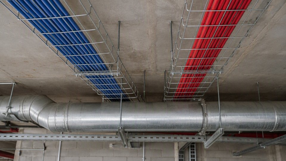
Dedicated raceways and conduits
For most building and industrial work, dedicated conduit or raceway is the safest design basis. That usually means separate routes for:
- Higher voltage power feeders and branch circuits.
- Motor leads, especially VFD output cables.
- 120 VAC or 230 VAC control wiring where used.
- 24 VDC and 48 VDC control circuits.
- Analog instrumentation such as 4-20 mA, RTD, thermocouple, load cell, and pulse signals.
- Communications such as Ethernet, fieldbus, RS-485, fiber, and building automation networks.
- Fire alarm, security, intercom, and safety-related low voltage systems where the governing rules require separation.
Good separation is not just the air gap. It includes field identification. Use durable labels on conduits, tray runs, pull boxes, junction boxes, and cabinet entries. On larger sites, route drawings should show voltage class, cable type, cable tag ranges, and spare capacity. A hand-marked panel schedule taped inside a door is better than nothing, but it is not enough for a plant that expects repeat modifications.
There is a practical maintenance reason for this. Once low voltage and power are mixed casually, technicians start treating every box as a general-purpose pulling point. A night-shift repair may add a spare 24 VDC pair next to a 480 V motor branch because “the conduit was already there.” That shortcut can create both compliance exposure and intermittent faults that take days to chase.
Cable tray separation options
Cable tray is often where designs get sloppy because a tray looks spacious compared with conduit. Space alone does not automatically make mixed services acceptable. The acceptable arrangement depends on the wiring method, cable construction, voltage rating, tray listing, local code, and any project standard imposed by the owner or insurer.
Common tray separation methods include:
| Method | Where it is used | Practical caution |
|---|---|---|
| Separate trays | Best for power versus instrumentation, data, and safety systems | Requires more supports and steel, but gives the cleanest inspection and maintenance boundary |
| Maintained spacing in the same tray route | Sometimes used where rules and cable types permit | Spacing must be maintained through bends, drops, and congested areas, not just on straight sections |
| Vertical separation | Useful in tray banks, pipe racks, and service corridors | Avoid placing sensitive signal cables directly below wet or damaged power cables where drainage or contamination is possible |
| Horizontal separation | Common on mezzanines, pipe bridges, and machine lines | Needs discipline at tray crossings and panel entry points |
| Tray dividers | Useful for organizing permitted cable groups | A divider is not magic; it must be suitable for the application and accepted by the applicable rule set |
| Listed barriers | Used where a physical barrier is required, not merely preferred | Verify the barrier system, tray fill, fastening, bonding, and inspection requirements |
| Rerouting away from high-current feeders | Best for instrumentation and communications near large drives, welders, heaters, and transformers | Longer cable length may be acceptable if it avoids recurring noise faults |
The mechanism is straightforward: high-current conductors create magnetic fields, and fast-switching loads create high-frequency noise. Long parallel runs give that noise time and length to couple into adjacent conductors. Analog inputs show it as unstable readings; Ethernet may show retries, dropped packets, or unexplained device faults; thermocouples may shift enough to make a loop tune badly. The closer and longer the parallel run, the worse the exposure tends to be, especially near VFD output cables and welding equipment.
For sensitive instrumentation and communications, separation distance is less valuable if the last 2 m inside the cabinet are bundled tightly with power wiring. Many otherwise good tray designs fail at the drop into the machine, where every cable gets zip-tied to the same strut because it looks neat.
Enclosure and panel segregation
Inside cabinets, separation has to continue beyond the gland plate. A control panel can have compliant field routing and still be noisy or hard to maintain if power and signal conductors are thrown into the same duct.
Good panel practice usually includes:
- Separate wireways for incoming power, motor wiring, control wiring, and instrumentation.
- Segregated ducts or trunking for AC control and DC control where the design calls for it.
- Internal barriers between power distribution and control electronics.
- Dedicated terminal blocks grouped by voltage and function.
- Separate gland plates or entry zones for power, controls, and communications.
- Physical spacing between drives, contactors, overloads, transformers, PLC I/O, analog modules, and network switches.
- Shield termination hardware provided near entry points rather than improvised pigtails stretched across the panel.
- Clear labels on spare terminals and spare conductors, including voltage classification.
There is a trade-off here. Larger panels and segregated ducts cost more and take floor or wall space, but they reduce commissioning time and future downtime. Dense panels may look economical at purchase, then punish the owner during every troubleshooting job because technicians must work near energized power while trying to test low voltage signals. The preferred choice flips only when the equipment is small, factory-listed as a complete assembly, and the manufacturer’s wiring method already addresses segregation, creepage, clearance, temperature rise, and service access.
When mixed conductors may be allowed
There are limited cases where different voltage conductors can occupy the same raceway or enclosure. A common condition is that all conductors have insulation rated for the highest voltage present, and the applicable rules permit those circuit types to be installed together. Typical building wire insulation ratings may be 300 V, 600 V, or 1000 V depending on cable type and governing standard, so the marking on the cable matters.
Low voltage conductors may be run with higher voltage conductors whenever the low voltage wire has the same insulation rating.False
Insulation rating is only one condition. The circuit class, cable type, wiring method, equipment listing, separation rules, and local code can still prohibit or restrict the mixed installation.
This is where procurement mistakes happen. A buyer sees “600 V insulation” on a control cable and assumes it can go anywhere a 600 V power conductor goes. Not necessarily. The cable may not be listed for that raceway use, the circuit class may require separation, the tray may not be approved for the mix, or the authority having jurisdiction may require a different method.
Associated circuits and machine wiring create another special case. In industrial machinery, control and power conductors may be routed together inside a listed or standards-built machine assembly when the relevant equipment standard, manufacturer instructions, and listing conditions permit it. Examples include motor control centers, packaged skids, OEM machine panels, and factory-assembled equipment. Do not generalize that permission to the whole building. What is acceptable inside a certified machine enclosure may not be acceptable in a site-installed conduit run across the plant.
Shielding helps noise; it does not replace safety separation
Shielded instrumentation cable is useful, but it is often oversold. Twisted pairs reduce loop area and help reject induced noise. Overall screens protect the cable bundle. Individual pair screens help when multiple analog signals share one cable and crosstalk matters. Drain wires give a practical termination path for the screen, usually at a defined grounding point based on the instrumentation design.
In practice, shield performance depends on:
- Pair twist consistency.
- Screen coverage and construction.
- Whether the shield is continuous through junction boxes.
- How the drain wire is terminated.
- Ground potential differences between equipment.
- Proximity to VFD output cables, large contactors, welders, and high-current bus.
- Whether spare pairs are grounded, isolated, or left floating according to the design.
Shielding reduces electromagnetic coupling; it does not make a communication cable safe to install in a power conduit if the governing rules do not allow it. I have seen Ethernet cable tied along a motor conduit with nylon cable ties because “it was shielded.” That is not an engineering method. It is a future failure report waiting for a hot day, a noisy drive, or a maintenance tech with side cutters.
Crossings, outdoor routes, and buried services
If low voltage and power routes must cross, cross them at roughly right angles and avoid long parallel runs where possible. A short perpendicular crossing gives less coupling length than a tidy-looking parallel route. Do not sacrifice mechanical protection or bend radius just to make a perfect 90-degree crossing, but use the principle whenever the layout allows it.
For underground and outdoor work, the design should cover more than voltage separation. It should include:
- Separate ducts for power, controls, communications, and spare capacity where practical.
- Spare conduits sized for credible future pulls, not just token small pipes.
- Pull boxes placed for cable pulling tension, bend limits, drainage, and inspection.
- Warning tape or marker systems above buried services.
- Moisture-rated, sunlight-resistant, or direct-burial-rated cables as required by the installation.
- Mechanical protection at risers, road crossings, exposed walls, and equipment pads.
- Sealing, drainage, or breathers where condensation is likely.
- Clear as-built drawings showing duct bank position, depth, route changes, and spare duct status.
Outdoor routing adds ugly details that office drawings miss: water in low points, crushed ducts after civil work, rodents in open tray, UV damage on jacket materials, and seasonal ground movement. A cable that was acceptable indoors may not be acceptable in a wet handhole or on a sun-exposed pipe rack.
Unsafe shortcuts are easy to spot once you know the pattern:
- Signal cable lashed to power conduit as a “support.”
- Ethernet, alarm, or instrumentation cable pulled through power conduit without verified permission.
- Junction boxes shared by different systems with no listed barrier or segregation.
- Spare conductors used later without confirming their original cable, voltage exposure, or destination.
- Tray dividers treated as universal approval for any cable mix.
- Panel duct covers hiding power and analog wiring bundled together for convenience.
- Unlabeled abandoned cables left in trays and reused because they happen to ring out with a meter.
The defensible design is the one an inspector can approve, a maintenance electrician can understand at 2 a.m., and the plant can expand without turning every spare cable into a risk. That boundary stops holding when a project has special classified areas, life-safety circuits, utility requirements, railway or marine rules, or OEM equipment listings that impose stricter separation. In those cases, the drawing should be checked against the current standard, the equipment documentation, and the site authority before the first conduit is bent.
Cable ratings and procurement checks
A cable order should be written around the circuit, installation route, environment, and governing standard, not around loose names like “low voltage cable” or “control cable.” A 600 V marking, for example, tells you the insulation voltage class; it does not by itself prove the cable may share a conduit, tray, panel compartment, or machine raceway with another circuit.
A cable voltage rating alone does not approve mixed installation with higher-voltage circuits.True
Mixed wiring approval depends on the applicable electrical code or product standard, conductor insulation rating, circuit class, enclosure or raceway method, separation barriers, signal performance needs, and the equipment manufacturer's installation instructions.
The purchasing mistake I see most often is simple: the buyer asks three vendors for “24 V control cable,” gets three different constructions, and only later discovers that one is a 300 V PVC control cable, one is an instrumentation cable with a thin overall shield, and one is a flexible machine cable meant for drag-chain service. All three may be legitimate products. They are not interchangeable.
Specification data buyers should request before asking for price
For mixed-route projects, the cable datasheet needs to be specific enough that engineering, installation, QA, and maintenance are all looking at the same product. At minimum, request or define:
- Conductor material: Usually copper for control, instrumentation, data, and most industrial power circuits; aluminum may be considered for larger power feeders where terminals, bending space, and code rules allow it.
- Conductor size: State AWG, mm², or kcmil clearly. Do not let vendors “equivalent” the size without checking voltage drop, fault current, terminal fit, and local standard acceptance.
- Voltage rating: Common building and industrial cable ratings include 300 V, 600 V, and 1000 V, depending on the cable type and governing standard. Project-specific MV or special equipment ratings need separate confirmation.
- Insulation compound: PVC, XLPE, PE, EPR, LSZH, silicone rubber, fluoropolymer, or other compounds behave very differently under heat, oil, moisture, and flame.
- Outer sheath or jacket material: The sheath is what the installer drags across tray edges, glands, panel holes, gravel, or wet trench surfaces. Jacket choice often decides cable life.
- Flame rating: Specify the required flame or fire performance by standard, not by marketing phrase. Tray flame, riser, plenum, LSZH, fire-resistant, and flame-retardant are not the same requirement.
- Temperature rating: Include both conductor operating temperature and ambient installation limits. A cable that is fine at 70°C in a ventilated tray may not be fine beside a furnace wall or under a sun-heated roof.
- Shielding: Define overall shield, individual pair shield, braid, foil, drain wire, shield coverage, and termination method where signal integrity or VFD noise is involved.
- Armor: Steel wire armor, steel tape armor, aluminum armor, or corrugated metal sheath may be needed for impact, rodent, burial, or industrial abuse, but it changes weight, bending radius, and gland selection.
- Oil resistance: Machine tools, stamping lines, hydraulic packs, and food plants can destroy ordinary PVC jackets faster than the electrical load ever will.
- UV resistance: Outdoor tray, rooftop, solar, yard, and marine-adjacent installations need sunlight-rated jackets where exposed.
- Water resistance: Wet locations, washdown areas, ducts, tunnels, underground routes, and flooded pull boxes need the right water-blocking or wet-location construction.
- Standard compliance: Name the required standard or approval path. For export projects, “IEC type,” “UL listed,” “CE declaration,” or “as per local code” must be clarified before production, not after shipment.
The commercially safe purchase order describes the cable construction and the installation duty; it does not rely on the cable family name alone.
Cable families are not interchangeable labels
A cable family name gives a starting point, but the construction inside that family can still vary. One tray cable may be suitable for exposed-run industrial tray in a specific jurisdiction; another may be allowed only inside tray and conduit. One data cable may be acceptable in a building plenum; another may be an industrial Ethernet cable with a rugged jacket but no building plenum rating.
| Cable family | Typical use | Procurement caution for mixed routes |
|---|---|---|
| Building wire | Branch circuits, feeders, panels, conduit wiring | Check insulation voltage class, wet-location rating, color coding, and whether individual conductors are permitted in the raceway system. |
| Power cable | Motors, feeders, distribution circuits | Confirm fault-duty suitability, conductor size, insulation system, armor or sheath, and termination accessories. |
| Control cable | 24 VDC, 48 VDC, 120 VAC, 230 VAC control circuits | Do not assume all cores are permitted near power conductors; verify voltage rating, flame rating, and panel wiring rules. |
| Instrumentation cable | Analog signals, sensors, transmitters | Shielding, pair twisting, capacitance, and grounding practice matter as much as voltage rating. |
| Data cable | Ethernet, fieldbus, communications | Electrical separation is often driven by signal performance and communications standards, not just shock protection. |
| Fire alarm cable | Alarm, detection, evacuation systems | Must match local fire code, circuit survivability requirements, color/marking rules, and listing requirements. |
| VFD cable | Inverter-fed motor circuits | Needs suitable insulation, shielding or armor design, grounding path, and jacket performance to control EMI and bearing-current issues. |
| Flexible machine cable | Moving equipment, robots, drag chains, tooling | Flex life, strand class, torsion rating, and minimum bend radius become purchasing criteria. |
| Tray cable | Industrial tray distribution and control | Confirm exposed-run permissions, tray flame rating, sunlight resistance, and installation method. |
| Armored cable | Impact-prone, industrial, outdoor, or buried routes | Armor helps mechanically but increases bending radius, pulling load, termination cost, and drum weight. |
| Outdoor direct-burial cable | Underground feeders, site lighting, yard systems | Requires wet-location and burial suitability, crush/impact protection, rodent strategy, and correct bedding practice. |
The trade-off is usually between a cable that is electrically adequate and one that is installation-proof. A lightly jacketed cable may pass the voltage requirement and cost less per meter, then fail early because it was pulled through a wet duct, rubbed on a tray edge, or exposed to coolant mist. The preferred choice flips when the route is clean, dry, enclosed, and well segregated; in that case overbuying armored or highly specialized cable can waste money and make installation harder.
Environmental checks that change the cable construction
Before releasing a bulk order, ask where the cable actually lives. “Indoor plant” is not enough; a mezzanine tray above a paint line is a different environment from an MCC room.
Check these conditions route by route:
- Indoor or outdoor service: Outdoor jackets need sunlight, temperature, and moisture resistance that many indoor control cables do not have.
- Wet locations: Consider washdown, condensation, flooded pull boxes, underground ducts, and seasonal water ingress. A winter-thaw sump surprise is not rare.
- Chemical exposure: Oils, cutting fluids, solvents, acids, alkalis, cleaning chemicals, and food-grade wash chemicals require jacket compatibility review.
- Mechanical impact: Forklift zones, crane bays, cable ladders near maintenance platforms, and low-mounted runs may need armor or physical guarding.
- Rodent risk: Utility tunnels, farms, grain facilities, warehouses, and outdoor trenches may justify armor, special sheathing, or route protection.
- Sunlight exposure: Rooftop tray and yard installations should not depend on indoor PVC unless the product is rated for UV exposure.
- Burial depth and soil conditions: Burial depth, bedding, backfill, drainage, and local rules affect whether direct burial is acceptable or conduit is required.
- Bending radius: Large power cables, armored cables, and shielded VFD cables need enough bend space at panels, motors, and trays.
- Moving equipment: Festoon systems, drag chains, robots, and lift tables need flexible constructions; ordinary stranded control cable is not a motion cable.
- Ambient temperature: Hot roofs, cold storage, furnace areas, and outdoor winter pulls can change both operating life and installation handling.
The mechanism is plain enough: heat accelerates insulation aging, oil extracts or softens certain jacket compounds, water attacks poorly sealed ends and terminations, and repeated bending work-hardens conductors strand by strand. A cable that fails electrically after two years often started as a mechanical or chemical mismatch on day one.
Documentation for international and bulk projects
For export procurement, the paper trail is not decoration. It is how the receiving team proves the delivered cable matches the design, customs paperwork, site inspection, and maintenance records.
Ask suppliers for:
- Technical datasheets showing conductor, insulation, sheath, voltage, temperature, flame, dimensions, weights, and installation limits.
- Factory test reports for the supplied batch or drum lot where applicable.
- Certificates and compliance declarations tied to the standard named in the purchase order.
- Packing lists with drum numbers, lengths, net and gross weights, and shipping marks.
- Drum schedules matched to pulling plans, so the site does not splice because the wrong length landed in the wrong area.
- Traceability records linking production batch, cable marking, drum label, and order reference.
- Project marking on the cable sheath when required: voltage class, cable type, standard, size, core count, manufacturer, meter marking, year, and project code.
Manufacturing controls that matter after installation
Mixed-route reliability depends partly on design separation, but cable build quality still matters. Conductor concentricity affects insulation uniformity. Insulation thickness and eccentricity influence dielectric margin and termination stripping behavior. Spark testing helps catch pinholes during production. Shield coverage affects noise rejection and grounding effectiveness, especially for instrumentation, encoder, and VFD-related circuits. Sheath integrity protects the cable during pulling and long service. Dimensional tolerance decides whether glands, lugs, seals, and tray fill calculations work cleanly on site.
Factory routine tests do not replace code compliance, but they reduce avoidable surprises. In practice, a few millimeters of jacket diameter error can turn into a container full of cables that do not fit specified glands, and nobody enjoys solving that at midnight with a knife and a box of wrong-size fittings.
Jinda’s integrated R&D, production, technical support, and export supply structure is relevant here because many international projects need more than a catalog match. With manufacturing scale across multiple production bases and experience serving overseas customers, the useful conversation is about matching cable construction to the local code framework, route environment, delivery volume, marking requirements, and documentation package.
Bulk buyers should send route drawings, circuit schedules, required standards, voltage classes, installation methods, environmental conditions, and expected procurement volume before asking for a generic low-voltage cable price. That gives the supplier enough information to propose a cable that can be built, documented, shipped, installed, and maintained without forcing the site team to solve specification gaps in the field.
Industrial installation examples
Factory motor circuit
A 480 V or 600 V motor feeder should normally be treated as a power route, not a convenient carrier for 24 VDC sensors, encoder cable, or Ethernet. The risk is worst around VFD output cables, motor starters, contactors, braking resistors, and long motor leads, where fast switching and high current changes create electrical noise as well as safety and maintenance exposure.
In practice, I would not bundle these together unless the machine documentation, cable listings, and applicable code clearly permit it:
- Across-the-line motor starters: contactor opening and closing produces transients that can upset nearby low-level circuits.
- VFD output cables: PWM switching edges couple noise into adjacent conductors through capacitance and magnetic field coupling.
- Encoder and resolver cables: position feedback errors can show up as nuisance trips, speed instability, or intermittent servo faults.
- Ethernet and fieldbus cables: communication errors may appear only during acceleration, braking, or high-load operation, which makes troubleshooting painful.
- 24 VDC proximity sensors: false input transitions can stop a line or, worse, mask an actual sensor change.
The common plant-floor mistake is tying everything to the same Unistrut run with cable ties because the route is short. A short bad route near a VFD can be worse than a longer clean route. If the motor circuit must cross signal wiring, cross at roughly 90 degrees, keep the parallel run short, and use shielded motor cable or metal raceway where the drive manufacturer requires it.
A 24 VDC sensor cable may be installed in the same raceway as a 480 V motor feeder if all conductors are insulated for the highest voltage present.False
Insulation rating is only one condition. Circuit class rules, cable listing, raceway fill, noise immunity, and local code restrictions still have to be satisfied; with VFD feeders or communications cable it is usually not acceptable without specific listed cable systems and engineering review.
Control panel wiring
Inside a control panel, mixed voltages are common, but they should not be mixed casually. A sound panel layout separates power distribution, 120 VAC control, 24 VDC control, PLC I/O, analog signals, safety circuits, and network cables by duct, barrier, terminal grouping, and clear labeling.
A practical layout often looks like this:
| Panel area | Typical circuits | Good installation practice |
|---|---|---|
| Main power section | Incoming supply, disconnect, fuses, breakers, contactors, drives | Keep in a defined power zone; use barriers or spacing where required |
| AC control section | 120 VAC or 230 VAC coils, relays, pilot devices | Separate from PLC low-voltage I/O where practical |
| DC control section | 24 VDC power supplies, sensors, solenoids | Use dedicated terminals and wire colors per plant standard |
| PLC and I/O section | Digital inputs, outputs, analog cards | Keep low-level analog away from coils, contactors, and drive wiring |
| Network section | Ethernet, fieldbus, remote I/O | Route in separate duct or a clean side of the enclosure; avoid sharing bundles with switching power |
| Safety section | E-stop, guard switches, safety relays, safety PLC I/O | Keep identification unambiguous; follow the machine safety design, not shop preference |
The mechanism is simple but often ignored: every long parallel conductor pair is a small transformer and capacitor. High-current switching circuits inject noise; high-impedance analog inputs and communication pairs are more likely to receive it. The trade-off is panel density. Tight panels save enclosure cost and floor space, but they punish maintenance crews later with heat, difficult tracing, and unexplained faults. That conclusion changes when a listed panel design or specific machine standard provides a permitted segregation method, but the documentation has to be kept with the equipment.
Building automation and low-energy systems
Thermostats, occupancy sensors, access control readers, alarm devices, intercoms, cameras, and BAS communication cables are often low-energy circuits, but they still need separation from lighting and receptacle wiring unless the applicable wiring method permits the combination. This is especially relevant for Class 2 circuits and communications cabling, where the cable jacket, listing, and installation rules matter as much as the nominal voltage.
Common field situations include:
- Thermostat cable near lighting circuits: acceptable routing depends on cable rating, circuit class, and separation method.
- Access control in door frames: keep reader and lock power wiring identified; do not borrow a nearby receptacle conduit because it is “only a short run.”
- Fire alarm and security circuits: these may have special survivability, monitoring, or listing requirements that override normal convenience routing.
- BAS communication trunks: keep away from fluorescent lighting ballasts, dimmers, contactors, and variable-speed fan drives where possible.
A renovation contractor may see an open conduit and assume it is spare. That assumption has burned many projects. Existing conduit may contain line-voltage conductors, abandoned wires, or circuits serving a different panelboard.
Instrumentation loop in a process plant
A 4-20 mA loop, RTD, thermocouple, load cell, or analyzer signal should be routed as instrumentation, not as general control wiring. Shielded twisted pair helps reject noise, but it is not magic; it works properly only when cable construction, separation, grounding, and shield termination match the instrument design.
Keep instrumentation away from:
- Large motor feeders
- Heater circuits
- SCR power controllers
- VFD input and output cables
- Solenoid valve banks with poor suppression
- Welding power and temporary maintenance leads
Shield termination is a detail worth checking before startup. Some systems require the shield grounded at one end only; others use a defined grounding bar or isolated shield terminal. If electricians “improve” the grounding by bonding both ends randomly, shield current can flow and create the very noise the shield was meant to prevent.
Cable tray corridor
A tray corridor should be designed as a route hierarchy, not a shared shelf. Power, control, instrumentation, network, and safety circuits have different risk profiles, and the tray arrangement should reflect that.
Typical options are:
- Separate trays: best for maintainability and future expansion; costs more steel, supports, and space.
- Tray dividers: useful where allowed, but the divider must be listed or accepted for the purpose.
- Vertical or horizontal spacing: practical in pipe racks and utility corridors; requires discipline during later additions.
- Route hierarchy: place high-power feeders on one level or side, control in a separate path, and instrumentation or data in the cleanest route available.
- Crossing control: where routes must intersect, minimize parallel exposure and cross cleanly.
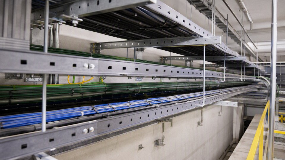
The trade-off is procurement and installation cost versus troubleshooting cost. Separate trays look expensive in the bid tab, but one intermittent encoder or network fault on a production line can consume more money than the tray steel ever did.
Underground duct bank
Underground work should use separate conduits for power and signal unless the design specifically permits a shared system. Once concrete is poured or trenches are backfilled, fixing a bad segregation decision is slow, dirty, and expensive.
A good duct bank design checks:
- Separate conduits for medium or low-voltage power, control, communications, and instrumentation
- Spare conduits for future circuits, not just spare fill in existing ducts
- Pull-box spacing and bend count so delicate cables are not damaged during pulling
- Waterproofing and drainage, because underground conduits often become wet locations
- Grounding and bonding continuity for metallic raceways and shields
- Permanent duct identification at manholes, handholes, panels, and as-built drawings
I have seen retrofit crews lose half a shift proving which duct goes where because old tags were painted over or buried under mud in a handhole. Documentation is part of the installation, not office paperwork.
Temporary, retrofit, and OEM export work
Temporary and retrofit additions are high-risk because they happen under schedule pressure. Existing conduits may already be full, labels may be wrong, abandoned conductors may still be energized, and a “temporary” cable tied to a tray can stay there for five years.
For maintenance and retrofit work, insist on:
- Field verification before pulling new cable
- Updated panel and route labels
- Conduit fill and derating checks
- Confirmation of circuit class and insulation rating
- Separation review for VFDs, networks, instrumentation, and safety circuits
- Removal or proper termination of abandoned conductors
For OEM machine exports, the destination market controls the design target. A machine wired to the builder’s local habit may still fail inspection overseas if the buyer requires compliance with NFPA, IEC, UL, CE-related documentation, or another applicable standard. The safe purchasing language is not “wire it like usual”; it is a written electrical specification tied to the destination country, supply voltage, control voltage, cable standards, panel labeling, documentation language, and inspection requirements.
Inspection and troubleshooting checklist
Use this checklist before approving a shared route, accepting a machine skid, modifying a panel, or blaming a sensor problem on “noise.” Do the paperwork first, then open covers. A surprising amount of mixed-voltage trouble starts as a drawing mismatch, not a bad cable.
- Collect the documents before touching the installation
- Single-line diagrams and control schematics.
- Panel layout drawings, terminal plans, and enclosure compartment details.
- Cable schedules, conduit schedules, tray layouts, and junction box lists.
- Equipment manuals for drives, PLCs, instruments, safety relays, communication modules, and packaged machines.
- Cable certificates, product datasheets, listing or approval documents, and purchase specifications.
- Previous inspection reports, nonconformance records, commissioning punch lists, and maintenance work orders.
I like to compare the cable schedule against the physical route before judging compliance. On older plants, the official drawing may show a spare conduit while the actual cable is cable-tied to a tray rung beside a motor feeder because “it was only temporary” six years ago.
- Identify every circuit in the shared route
For each cable or conductor group, record:- Nominal voltage: for example 12 VDC, 24 VDC, 48 VDC, 120 VAC, 230 VAC, 400/480 VAC, or medium-voltage if present.
- Function: power, control, instrumentation, network, safety, fire alarm, interlock, lighting, heating, or monitoring.
- Energy limitation or circuit class, where applicable.
- Source panel or supply device.
- Overcurrent protection rating and type.
- Destination equipment, terminal strip, junction box, or field device.
- Whether the circuit is normally energized, intermittently energized, switched by a VFD, or only live during fault or emergency conditions.
This step matters because voltage alone does not tell the whole story. A 24 VDC discrete input cable beside a clean 120 VAC control circuit is a different risk from a 24 VDC encoder cable running parallel to a VFD output. The first may be mainly a code and insulation-rating question; the second can become a production fault generator.
Read the cable markings, not the purchase nickname
Check the outer jacket or conductor insulation for:- Voltage rating, commonly 300 V, 600 V, or 1000 V depending on cable type and governing standard.
- Cable type and listing or certification mark.
- Temperature rating.
- Flame or fire-performance rating required for the installation area.
- Conductor size and conductor material.
- Shielding type: foil, braid, drain wire, individual pair shield, overall shield, or armor.
- Manufacturer name or identification and batch traceability where available.
If the marking is missing, illegible, painted over, or buried inside conduit with no accessible record, treat that as an unresolved inspection item. Do not assume a cable is acceptable because it “looks like control cable.” Procurement descriptions are often too loose; the jacket marking and certificate are what you can defend.
Low voltage conductors may be subject to the insulation rating, separation, and circuit-class rules of the higher-voltage wiring route, not just their own operating voltage.True
Mixed routing is normally judged by the applicable electrical code, product listing, enclosure design, circuit classification, and the voltage exposure created by adjacent circuits. The exact permission must be verified against the local code and equipment documentation.
- Inspect physical separation continuously
Look at the complete route, not just the clean section near the panel:- Dedicated conduit or raceway for different circuit groups.
- Listed barriers or dividers in cable tray.
- Separate compartments inside control panels and junction boxes.
- Segregated wire duct in panels, especially between field I/O, mains power, VFD wiring, and safety circuits.
- Gland plate layout and gland spacing where cables enter enclosures.
- Pull boxes, marshalling boxes, terminal chambers, and field junction boxes.
- Termination points where separation often collapses in the last 300 mm.
The weak point is usually a transition: tray to conduit, conduit to panel, panel duct to terminals, or a multi-cable gland plate added during a shutdown. Separation that disappears at the pull box or terminal strip is not really separation.
Look for common defects that change the decision
- Mixed low-voltage and higher-voltage conductors in the same conduit without documented permission.
- Damaged jackets, crushed cable, insulation cuts, oil swelling, UV cracking, or heat hardening.
- Overcrowded wireways that force power and signal conductors into contact.
- Missing bushings, sharp knockout edges, poor strain relief, or unsealed glands.
- Unlabeled spare conductors terminated on live blocks or left floating.
- Abandoned conductors still present in conduit or tray.
- Improvised cable ties, plumbing clamps, scrap wire lashings, or cable resting on hot pipework.
- Low-voltage data, sensor, or thermostat cable entering a power enclosure without a barrier or approved compartment.
- Shield drain wires pigtailed randomly to several ground points because someone was chasing noise on night shift.
Some of these defects are safety issues; others are reliability issues. Both cost money. A random analog trip that stops a line twice a week can be more expensive than a neat reroute, even if nobody gets shocked.
Connect symptoms to possible wiring causes
| Field symptom | Wiring issue to investigate first |
|---|---|
| Random alarms or sensor chatter | Shared route with motor starters, contactor coils, solenoids, or poor DC common grounding |
| Unstable analog readings | Shield termination errors, long parallel runs with power cables, damaged instrument cable, ground potential difference |
| Data dropouts or communication retries | Tray sharing with VFD output cables, poor shield continuity, wrong cable type, excessive bend or jacket damage |
| Encoder faults | Proximity to VFD motor leads, inadequate shielding, incorrect grounding, mixed terminations in a noisy panel |
| Failures only under load | Inductive or capacitive coupling from high-current conductors, heating in crowded duct, voltage dip at control supply |
| Noise after equipment upgrade | New drive, soft starter, servo, heater controller, or switching power supply added to an old shared route |
The mechanism is straightforward: changing current and voltage in power conductors can couple energy into nearby signal conductors through magnetic and electric fields. Longer parallel runs, closer spacing, high switching frequency, poor shielding, and weak grounding make it worse. The trade-off is route economy versus diagnostic risk; sharing tray space saves steelwork and installation labor, but it can leave maintenance chasing intermittent faults with a meter at 2 a.m.
- Use tests that match the circuit
- Insulation resistance testing where suitable and permitted by the equipment manufacturer. Disconnect sensitive electronics before applying test voltage.
- Continuity checks for conductors, spares, shields, and protective earth.
- Grounding and bonding verification between panels, trays, machines, and field junction boxes.
- Shield continuity and shield termination checks; confirm whether the design calls for one-end or both-end bonding.
- Network cable testing for industrial Ethernet, RS-485, fieldbus, or similar systems using suitable testers, not only a basic continuity buzzer.
- Thermal inspection of crowded ducts, terminals, overloaded conductors, and suspect glands while the system is operating under representative load.
- Waveform, transient, or noise analysis for sensitive analog, encoder, load cell, or high-speed communication circuits.
Testing has limits. An insulation test can find a damaged jacket or wet conduit, but it will not prove that a 4-20 mA signal is immune to a nearby drive output. For noise problems, test during the machine state that creates the fault: acceleration, heater firing, solenoid cycling, welding, or compressor start.
Document corrective actions clearly
Record what must change, who owns it, and what approval is required:- Reroute low-voltage or sensitive circuits into dedicated conduit or tray.
- Add listed barriers, tray dividers, or separate enclosure compartments.
- Replace underrated or unlisted cable with cable suitable for the installed environment and required voltage exposure.
- Improve bonding, grounding, and shield termination according to the equipment manual and project standard.
- Separate VFD output cables from instrumentation, encoder, network, and safety circuits.
- Remove abandoned conductors and label legitimate spares at both ends.
- Update cable tags, terminal labels, panel drawings, cable schedules, and inspection records.
- Obtain authority, engineer, insurer, or customer approval where the applicable procedure requires it.
Do not perform energized inspection, testing, or modification unless you are qualified, authorized, and working under the applicable electrical safety procedure for that site. Covers, trays, and junction boxes can contain circuits that are not shown on the drawing, especially after years of maintenance changes, so verify absence of voltage and lockout requirements before putting hands or tools into the installation.
Frequently asked questions
Can low voltage and high voltage share the same conduit?
Usually, do not put low voltage and power conductors in the same conduit by default. It may be permitted only where the circuit types are allowed to occupy the same raceway, every conductor insulation is rated for the highest voltage present, and the installation method is accepted by the applicable electrical code.
That last point matters. A 24 V signal cable with 600 V insulation is not automatically legal beside a 230 VAC feeder if the circuit is classified as a separated communications, Class 2, fire alarm, or data circuit. Conduit fill, derating, identification, termination space, and future maintenance access still need checking.
Can 24 VDC control wire run with 120 VAC or 230 VAC wire?
Sometimes, but separation is usually the cleaner design. In industrial control panels, 24 VDC control wiring and 120 VAC or 230 VAC control wiring may be allowed in the same enclosure under specific wiring rules, insulation ratings, and segregation practices.
In practice, I prefer separate wire duct or at least separated duct fingers for PLC inputs, analog signals, solenoid outputs, and AC control power. It reduces nuisance faults and makes troubleshooting easier at 2 a.m. when someone is chasing an intermittent prox sensor near a contactor coil. The decision depends on:
- Circuit classification
- Insulation voltage rating
- Panel standard being applied
- Whether the wiring is inside a listed assembly
- Noise sensitivity of the signal
- Local inspection requirements
Can thermostat wire run with power wire?
Typical thermostat cable should not share a power conduit or power box unless the installation uses an approved separation method, such as a listed barrier or another code-compliant arrangement. Most thermostat wiring is treated as low-energy control wiring, often Class 2, and is not intended to be mixed casually with branch-circuit conductors.
A common bad installation is pulling 18/2 thermostat cable through the same conduit as a 120 VAC furnace feed because the path is convenient. The risk is not only shock exposure; a damaged conductor or wrong termination can put line voltage onto a thermostat circuit and destroy controls.
Can Ethernet cable run beside power cable?
Ethernet cable should be separated from power wiring and should not be pulled through the same conduit as power conductors unless a specifically permitted system is being used. Keep long parallel runs away from VFD output leads, large motor feeders, welders, contactors, and poorly bonded cable tray sections.
Short proximity is not the same as bundling for 40 meters. A brief crossing is usually manageable; a long parallel run beside a noisy motor circuit can cause packet loss, communication dropouts, or hard-to-repeat machine faults. Shielded industrial Ethernet helps, but proper grounding and physical routing still matter.
Is shielded cable enough to allow mixed routing?
No. Shielding helps reduce electromagnetic noise, but it does not automatically satisfy electrical safety separation, insulation, listing, or circuit-class rules.
Shield performance also depends on termination. A foil shield floating at both ends may do little against common-mode noise. A braid shield bonded poorly through a painted gland plate can behave differently from the drawing. Use shielding for signal quality; use approved barriers, conduit separation, insulation ratings, and code-compliant wiring methods for safety and compliance.
Shielded cable alone does not make a low voltage circuit code-compliant for installation with power conductors.True
Shielding is primarily an electromagnetic compatibility measure. Mixed routing still depends on circuit classification, conductor insulation rating, approved wiring method, and the applicable electrical code or equipment standard.
Can low voltage and power cables cross?
Yes, crossings are usually less problematic than long parallel routing, provided the cables are protected and the installation remains code-compliant. A right-angle crossing is commonly preferred because it minimizes the length over which noise can couple from the power circuit into the low voltage circuit.
Do not use “it only crosses once” as an excuse for poor mechanical protection. Watch for crushed tray corners, sharp conduit edges, wet trench bottoms, and tie-wrap bundles that slowly turn into permanent mixed-voltage harnesses after maintenance crews add more cables.
Does a 600 V rating on control cable solve the issue?
A 600 V insulation rating may solve one part of the problem, but not the whole problem. It can help meet the requirement that conductors in the same raceway or enclosure be insulated for the highest voltage present, where that rule applies.
It does not override restrictions on separated extra-low-voltage circuits, communications cable, listed cable assemblies, fire alarm circuits, or manufacturer instructions. It also says little about signal performance. A 600 V-rated analog cable run beside a VFD output may be electrically safe but still produce a noisy 4-20 mA signal if routing, shielding, and grounding are poor.
Can different voltages share a junction box?
They may share a junction box only when the box arrangement, conductor insulation, spacing, barriers, fittings, and circuit types are permitted by the applicable code. A listed divider or separate compartment is often the practical way to keep power wiring and low voltage wiring in the same physical box footprint without mixing them electrically.
Be careful with oversized generic boxes used as “everything boxes.” Once maintenance adds a power splice, a sensor terminal strip, a door switch, and a spare cable gland, the original separation can disappear. Labeling and physical segregation matter as much as the first-day drawing.
What should I do if mixed wiring already exists?
- De-energize where possible and follow the plant’s lockout procedure before opening raceways, boxes, or panels.
- Identify each circuit by source, voltage, function, and protective device.
- Check cable markings for insulation rating, cable type, listing, and temperature rating.
- Compare the installation against the applicable code, project specification, and equipment manual.
- Look for damage, heat discoloration, crushed insulation, water entry, overloaded conduit, and unsealed fittings.
- Test only with suitable meters and qualified personnel.
- Plan corrective work where separation, barriers, or cable replacement are required.
If production cannot stop immediately, document the risk and create a controlled repair plan. Temporary “we will fix it later” wiring has a way of becoming permanent.
Who should decide the final installation method?
The final method should be confirmed by a qualified electrical engineer, licensed electrical contractor, project inspector, or the authority having jurisdiction. For machinery, the equipment builder’s standard and the current electrical schematic also need to be checked.
Procurement teams should not be left to settle this from a cable description alone. Ask for the circuit classification, required voltage rating, installation environment, tray or conduit arrangement, and applicable standard before buying cable in bulk. That prevents the expensive mistake of purchasing technically good cable that the installer or inspector cannot approve for the intended mixed-voltage route.
Verify your wiring plan
Do not run low voltage wire with higher voltage wiring unless three things are already clear: the applicable code permits it, the cable insulation and listing fit the highest circuit voltage present, and the installation controls shock, fire, maintenance, and interference risk. If any one of those is uncertain, design for separation first; it is usually cheaper than proving a mixed installation is acceptable after the tray, conduit, or panel is already built.
Low-voltage and higher-voltage conductors may share a route only when the applicable code or standard permits the arrangement and the cable construction is suitable for the highest voltage and installation method.True
This reflects the common code logic used in many jurisdictions, but the exact permission depends on circuit class, cable listing, enclosure or raceway type, and the local adopted standard.
Use a short verification sequence before issuing the purchase order or releasing installation drawings:
- Classify every circuit.
Separate power, control, instrumentation, data, fire alarm, safety, and communications circuits on the schedule. A 24 VDC solenoid circuit, a 24 VDC analog transmitter loop, and an Ethernet cable are not the same design problem, even though all may be called “low voltage” by someone on site. Identify the governing standard and destination market.
The answer can change between a North American plant panel, an IEC-style machine package, a marine installation, a utility project, or a building fire alarm system. Do not let a supplier quotation become the code decision. The project engineer, local authority, inspector, or qualified electrical contractor needs to confirm the rule set.Confirm cable ratings, listings, and construction.
Check rated voltage, insulation type, conductor size, temperature rating, shielding, armor, flame performance, oil or UV exposure, and whether the cable is listed or certified for the intended wiring method. Typical building and control cables may be rated around 300 V, 600 V, or 1000 V depending on type and standard, but that number alone does not approve mixed routing.Choose the separation method before buying cable.
Practical options include:- Dedicated conduit or raceway
- Separate cable tray routes
- Divided cable tray with a listed barrier
- Separate control panel compartments
- Listed barrier systems inside enclosures
- Cables rated and permitted for the highest circuit voltage where the applicable code allows that arrangement
- Document the route, not just the cable type.
Mark where low voltage and higher voltage circuits cross, share trays, enter cabinets, pass through junction boxes, or terminate near drives, contactors, transformers, heaters, and power supplies. Most bad mixed-voltage installations I have seen were not caused by one wrong cable; they were caused by several “temporary” routing decisions that became permanent after commissioning. Review the plan with qualified personnel before installation.
A 20-minute drawing review can prevent a two-day shutdown later. Include maintenance in the review if they will be the people opening the enclosure at 2 a.m. with a meter and a flashlight.
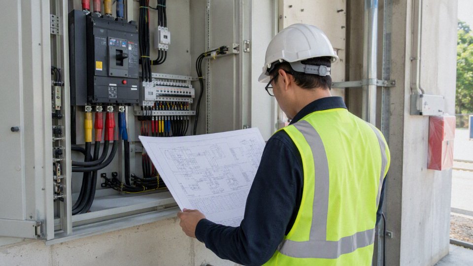
The mechanism is simple but unforgiving. Higher-voltage power conductors can impose electrical noise into adjacent signal circuits by capacitive or inductive coupling, especially near VFD output cables, motor starters, solenoid banks, and long parallel tray runs. At the same time, insulation damage, wrong terminations, or a misplaced field modification can put a technician or a PLC input card in contact with energy it was never meant to see. Shielding helps with noise; it does not automatically solve code separation or personnel protection.
There is a commercial trade-off here. Combined routing can save tray space, conduit, gland plates, panel real estate, and installation labor. Separation costs more up front, but it often wins once you price nuisance trips, unstable analog readings, failed inspections, damaged electronics, re-pulling cable through finished areas, and production time lost while people argue over who approved the route. The point where combined routing starts to make sense is usually where the circuits are properly classified, the cables are correctly rated and listed, the physical pathway is controlled, and qualified reviewers agree before material is ordered.
Buyers should treat cable selection and route design as one decision. A technically excellent cable can still be rejected if it is installed in the wrong tray, mixed with the wrong circuit class, or supplied without the certificate required for the destination market.
For quotation or specification review, prepare the following information:
- Substrate or installation environment: building, machine, tray, conduit, underground, outdoor, marine, mining, or other service
- Circuit type and voltage: for example 24 VDC control, 4-20 mA instrumentation, 230 VAC control, 480 VAC power, or VFD motor output
- Conductor size, core count, and grounding requirements
- Shielding, screen, drain wire, armor, or mechanical protection requirements
- Temperature, oil, chemical, UV, moisture, abrasion, and flame exposure
- Approximate route length, tray or conduit arrangement, and whether mixed-voltage routing is proposed
- Destination market and required certificates, standards, or project specifications
- Drawings, cable schedule, panel layout, site photos, or sample cable if replacement is involved
Jinda’s technical and sales team can review project cable specifications, discuss suitable cable constructions, and support bulk procurement for industrial power, control, instrumentation, and special cable requirements. Send the cable schedule and route conditions first; that gives the team enough context to respond with a construction that fits both the electrical duty and the way the cable will actually be installed.