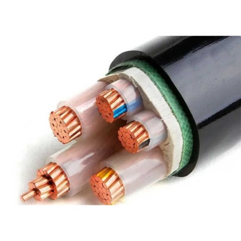
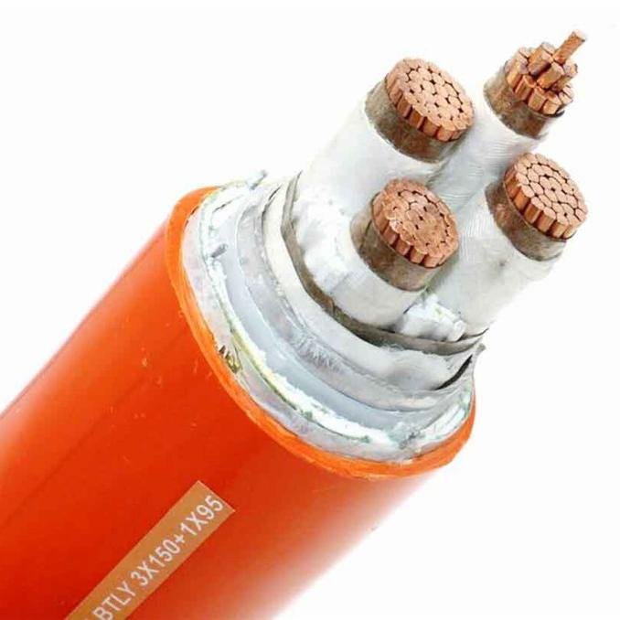
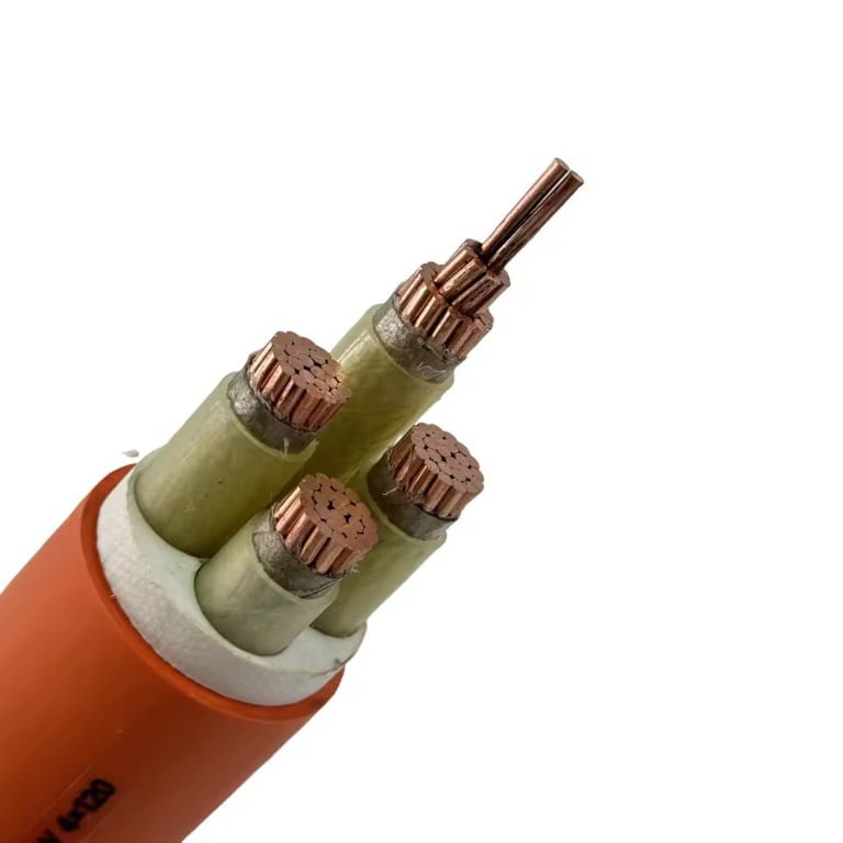
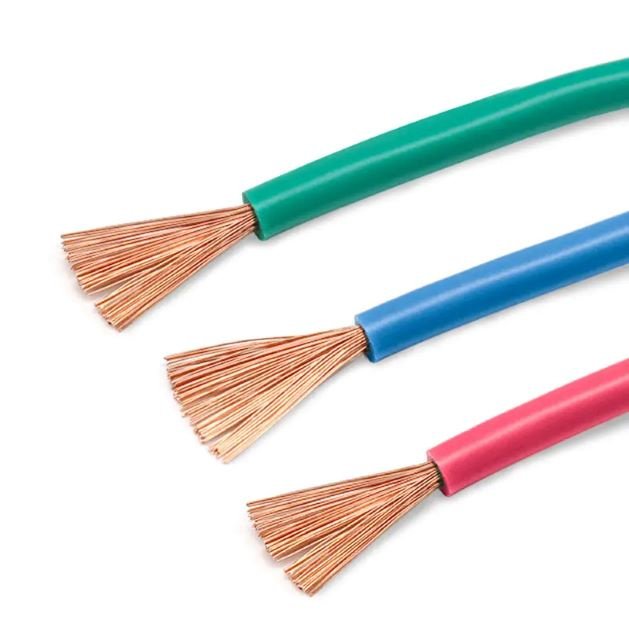
Misclassifying a 480 V system sounds like paperwork until a buyer orders the wrong cable class, a contractor prices the wrong gear, or maintenance treats a dangerous low-voltage lineup too casually. That mistake can show up as failed inspections, oversized procurement packages, arc-flash exposure, or weeks lost waiting on replacement cable. The right starting point is to separate voltage classification from hazard level and then specify cable by system voltage, grounding, installation, and applicable standard.
No, 480 V is normally not considered medium voltage. In common North American and IEC practice, a 480 V three-phase system is classified as low voltage; IEC low voltage commonly extends up to 1,000 V AC, while many cable and utility medium-voltage categories begin above 1 kV.
That answer is simple, but the purchasing decision behind it is not always simple. A 480Y/277 V plant service, a 480 V delta system, a 600 V-rated cable, and a 2 kV industrial cable can all appear in the same project discussion, and mixing those terms loosely is how specifications drift from safe and economical into expensive or noncompliant.
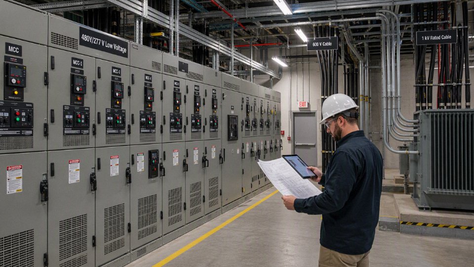
Voltage-class definitions
A voltage class is a standardized engineering bucket, not just a casual label on a nameplate. It groups systems and equipment so designers can select insulation systems, test levels, switchgear, protective devices, terminations, work practices, and documentation without redefining the whole electrical universe on every project.
Under common IEC usage, low voltage covers AC systems up to 1,000 V, so a 480 V three-phase system sits comfortably inside the low-voltage range. That does not make it harmless; it only tells you which family of equipment and standards you are working in before you deal with fault current, grounding, arc energy, and installation environment.
In plant language, “voltage class” often gets used loosely. A maintenance electrician may say “the medium-voltage room” because it contains the plant’s service entrance and the big transformers, while the project specification may reserve “medium voltage” for 5 kV, 15 kV, or 35 kV cable systems. Procurement people then get caught in the middle: one drawing says 480 V distribution, a bill of materials asks for 1 kV cable, and a supplier catalog has a tab called “low voltage power cable.” The only safe way through that is to separate the system voltage from the equipment rating and the market category.
A practical voltage-class framework looks roughly like this, though the exact boundary must always be checked against the governing standard and contract documents:
| Term used in projects | Common engineering meaning | Typical cable or equipment examples | Procurement caution |
|---|---|---|---|
| Extra-low voltage | Low-energy control, signaling, electronics, instrumentation, depending on the standard | 24 V DC controls, sensors, some communications circuits | Do not assume shock risk is the only concern; noise, segregation, and hazardous-area rules may matter |
| Low voltage | Commonly up to 1,000 V AC in IEC practice; North American usage may refer to 600 V or 1,000 V boundaries depending on context | 120/208 V, 277/480 V, 347/600 V systems; 600 V or 1 kV cable | 480 V belongs here by class, even when short-circuit energy is severe |
| Medium voltage | Generally above low-voltage limits; cable-market categories often start at 5 kV or 8 kV and run through 15 kV, 25 kV, 35 kV classes | Shielded MV cable, metal-clad switchgear, pad-mounted transformers, MV terminations | Requires a different insulation, shielding, testing, termination, and maintenance mindset |
| High voltage and above | Utility transmission, sub-transmission, special industrial systems | Transmission cable, substations, GIS, overhead lines | Definitions vary more by utility, region, and standard family |
The mechanism behind these categories is simple but important: as system voltage rises, the electrical stress across insulation and air gaps increases, and the equipment must control that stress predictably over years of heat, moisture, contamination, switching surges, and maintenance handling. That is why medium-voltage cable is normally shielded, stress-controlled at terminations, and tested differently from ordinary 600 V or 1 kV low-voltage power cable. You do not just “buy thicker insulation” and call it medium voltage; the cable construction, accessories, field testing, splicing skills, and failure modes all change.
North American terminology deserves a little care. Older habits in industrial plants often treat 600 V as the big dividing line because so much equipment, cable, panelboard, and motor-control hardware was historically organized around “600 V class” products. Newer code and product discussions may use 1,000 V as a meaningful boundary in certain contexts. Both patterns show up in drawings, specifications, and supplier conversations, especially in brownfield facilities where the MCCs were installed in the 1990s and the project specifications were rewritten last year.
That is why a buyer should not ask only, “Is this medium voltage?” Ask these questions instead:
- What is the nominal system voltage?
- For a common 480Y/277 V system, the line-to-line voltage is 480 V and the line-to-ground voltage is 277 V.
- For a 480 V delta system, grounding and fault behavior can be quite different, especially on corner-grounded, ungrounded, or high-resistance-grounded systems.
- What voltage rating must the cable or equipment carry?
- A 480 V feeder commonly uses 600 V rated cable in many North American installations.
- Some projects specify 1 kV rated cable because of the governing standard, export market preference, installation conditions, or procurement standardization.
- A 1 kV cable rating does not convert the 480 V system into medium voltage.
- Which standard governs the job?
- IEC-based project specifications may define low voltage up to 1,000 V AC.
- North American industrial documents may refer to 600 V class gear, 1,000 V limits, or code-specific language.
- Marine, mining, renewable energy, oil and gas, and utility projects may have their own vocabulary layered on top.
- What equipment family is actually being purchased?
- Low-voltage power cable: often 600 V or 1 kV rated, depending on market and construction.
- Low-voltage switchgear and switchboards: commonly used for 480 V distribution.
- Medium-voltage cable: often appears in 5 kV, 8 kV, 15 kV, 25 kV, and 35 kV catalog structures.
- Medium-voltage switchgear: built around different interrupting ratings, insulation systems, compartments, testing, and operating procedures.
The most common procurement mistake is treating the cable voltage rating as the voltage class of the electrical system. A 480 V motor feeder specified with 1 kV rated cable is still a low-voltage feeder; the cable rating is the maximum voltage class of that cable construction under the applicable standard, not a reclassification of the plant distribution system.
The trade-off shows up when engineers standardize cable ratings. Using 1 kV low-voltage cable on a 480 V project may simplify global purchasing, provide a bit more insulation margin, and align better with IEC-style documentation. The price is not only material cost; it can mean larger outside diameter, bigger glands, tighter tray fill, larger bending radius, heavier pulls, and more awkward terminations in a crowded MCC bucket. In a clean new installation, that cost may be acceptable. In a retrofit where the tray is already packed, the higher-rated cable can create more mechanical trouble than electrical benefit.
Medium-voltage cable selection is a different purchasing exercise. At 5 kV and above, the buyer is normally dealing with insulation level, conductor shield, insulation shield, metallic shield or tape screen, jacket construction, terminations, partial discharge considerations, and field test requirements. Accessories become part of the design, not an afterthought. A plant that treats 5 kV cable like oversized 480 V cable usually pays later through termination failures, nuisance outages, or long repair windows because the right jointer and test equipment are not on site.
Industry language can blur the line. Utilities may call their distribution feeders “primary” rather than simply medium voltage. Mining projects may focus on trailing cable ratings and grounding conductors because movable equipment changes the risk picture. Offshore and marine specifications may sort cables by fire performance, halogen content, armor, and approvals as much as voltage. Solar and battery projects may include 1,000 V or 1,500 V DC circuits that do not fit neatly into the mental model of a 480 V AC factory bus. Building services teams may call everything beyond branch panels “high voltage,” even when the engineer’s standard says otherwise.
For that reason, purchase documents should state the facts instead of relying on the nickname. A good cable line item for an industrial project normally includes:
- Nominal system voltage, such as 480Y/277 V AC, three-phase, four-wire.
- Grounding method, such as solidly grounded wye, resistance grounded, ungrounded delta, or corner-grounded delta.
- Required cable voltage rating, such as 600 V or 1 kV, tied to the relevant standard.
- Conductor material and size, including copper or aluminum.
- Insulation type, jacket type, flame or oil resistance requirements, and installation environment.
- Applicable standard, project specification, and any national code requirements.
- Test, inspection, documentation, and marking requirements.
- Accessories required, including glands, lugs, terminations, trays, conduits, or armoring.
Voltage class also should not be confused with insulation coordination. Insulation coordination deals with expected overvoltages, protective devices, clearances, creepage distances, impulse withstand, surge protection, and how the system survives abnormal events. A 480 V panel in a harsh facility with long cable runs, frequent switching, VFDs, and poor grounding may need more careful surge and transient treatment than the words “low voltage” suggest.
It is also separate from overvoltage category. Overvoltage category is tied to where equipment sits in the electrical installation and what transient stresses it may see. A meter used at a service entrance faces a different transient environment than one used on a protected control circuit, even if both touch nominally low-voltage conductors. That is a tool-rating and safety issue, not a rebranding of 480 V as medium voltage.
Arc-flash risk is another separate question. A 480 V switchboard fed by a large transformer can deliver frightening incident energy if clearing times are long and fault current is high. The voltage class tells you the family of equipment; it does not tell you whether the worker can safely open a door, rack a breaker, or troubleshoot with the line energized. That answer requires short-circuit data, protective device settings, working distance, enclosure type, maintenance condition, and the current safety standard or facility procedure.
The boundary of this classification is reached when a project specification, legal code, utility rule, or equipment standard defines terms differently for that exact job. In that case, use the project’s governing definition in the paperwork, but still keep the engineering facts visible: a 480 V nominal AC system, its grounding method, the required cable rating, and the applicable product standard. That prevents a label from driving the wrong purchase.
Why 480 V feels different
480 V feels “bigger” than ordinary low voltage because it is normally the first voltage many plants use for heavy three-phase loads, high available fault current, and equipment that can hurt people quickly when something is loose, wet, miswired, or poorly maintained. The classification is still low voltage, but the operating consequences are industrial, not domestic.
Most electricians, mechanics, and production supervisors do not talk in IEC category language on the shop floor. They compare 480 V against what they have touched before: 120 V receptacles, 208 V panels in light commercial buildings, 240 V single-phase equipment, and then the 480 V gear feeding a 150 hp pump or a plant air compressor. That is why someone may casually call 480 V “high voltage” even though, for cable and standards classification, it is not medium voltage.
The informal language is understandable. Compared with familiar lower-voltage systems, 480 V changes several things at once:
- 120 V single-phase is common for lighting, control power, small tools, office loads, and receptacles. It can still kill, especially through wet skin or across the chest, but the connected loads and fault levels are often smaller.
- 208Y/120 V three-phase is common in commercial facilities and smaller industrial panels. It supports three-phase loads, but motor current is higher for the same horsepower than at 480 V.
- 240 V single-phase or three-phase appears in shops, farms, older equipment, and some process skids. Grounding arrangements vary, and assumptions get dangerous fast.
- 480Y/277 V three-phase is a standard industrial workhorse in North America. It runs motors, pumps, chillers, compressors, conveyors, fans, extruders, packaging lines, welders, and large HVAC equipment without the conductor size penalty that lower voltage would impose for the same power.
That last point is the practical reason 480 V gets respect. For a given power load, higher voltage means lower current, which can reduce conductor size, voltage drop, heat loss, and switchgear bulk. The trade-off is that the system is now feeding equipment with enough capacity behind it to turn a bad termination, a dropped tool, or a failed insulation sleeve into a violent event. The voltage label alone does not tell you how violent; the upstream transformer and protective device behavior often matter more.

Three-phase power also changes how faults behave. A 480 V motor control center may be fed from a transformer with substantial short-circuit current available at the bus. If a phase-to-phase fault occurs inside a starter bucket or disconnect, the event is not comparable to a tripped breaker on a small 120 V branch circuit. The current rises extremely fast, magnetic forces move conductors, copper can vaporize, and pressure builds inside an enclosure that was never meant to be open under fault conditions.
The shock hazard deserves the same discipline. In a typical 480Y/277 V grounded wye system, 480 V is the line-to-line voltage and 277 V is the line-to-ground voltage. A person contacting one phase and grounded metal may be exposed to roughly 277 V; contact across two phases can expose them to 480 V. Neither exposure belongs in the “it’s only low voltage” mental bucket.
Before planning work, confirm the actual system configuration, not just the number on the panel nameplate:
- Solidly grounded wye, commonly 480Y/277 V, with predictable line-to-ground voltage and high ground-fault current if the fault path is solid.
- Corner-grounded delta, where one phase is intentionally grounded and measurements can surprise technicians who assume wye behavior.
- High-resistance grounded systems, often used to limit ground-fault current and maintain continuity for certain industrial processes, but requiring ground-fault monitoring and trained response.
- Ungrounded delta or impedance-grounded systems, where the first ground fault may not trip immediately, but transient overvoltage and second-fault behavior become serious concerns.
- Separately derived or equipment-specific arrangements, especially around drives, transformers, imported machines, and process skids.
In practice, I want the one-line diagram, transformer nameplate, grounding method, available fault-current marking, and recent maintenance history before anyone starts treating a 480 V cabinet as routine. A missing bonding jumper or a high-resistance lug is not paperwork trivia; it changes what happens when insulation fails.
Arc flash is where 480 V most often earns its reputation. Incident energy is driven by several variables working together, not by voltage alone:
- Available short-circuit current from the transformer, utility source, generators, and parallel feeds.
- Protective-device clearing time, including breaker settings, fuse type, instantaneous pickup, short-time delay, and whether maintenance mode is active.
- Working distance, because energy at the worker’s body changes with distance from the arc source.
- Enclosure geometry, since an arc in a deep motor control bucket or switchboard cell can direct energy outward differently than an open-air arc.
- Maintenance condition, including oxidized bus joints, loose lugs, contaminated insulation, missing barriers, and old breakers that no longer trip as expected.
- System grounding and fault path, which affect whether an arcing fault sustains, how protective devices see it, and how quickly the event is interrupted.
The counter-intuitive part is worth saying plainly: some low-voltage 480 V equipment can produce higher arc-flash incident energy than some medium-voltage circuits. That can happen when a large low-voltage transformer supplies high fault current but the protective device has a time delay before it clears. A medium-voltage feeder with well-coordinated relays and fast interruption may expose a worker to less calculated incident energy at a given task location than a poorly coordinated 480 V switchboard.
480 V is technically low voltage, but it can still present severe shock and arc-flash hazards.True
Common voltage-class conventions place 480 V below medium-voltage thresholds, while hazard severity depends on current path, available fault current, clearing time, enclosure conditions, grounding, and work practices.
This distinction affects behavior. Treating 480 V as medium voltage for procurement classification can lead to oversized or incorrectly specified cable, terminations, and accessories. Treating 480 V as harmless because it is “only low voltage” can put a mechanic or electrician in front of an energized enclosure without proper lockout, absence-of-voltage verification, PPE, labels, insulated tools, or barriers. The first error wastes money; the second can get someone burned or killed.
Cable selection sits right in the middle of this discussion. A 480 V circuit may use 600 V, 1 kV, or sometimes 2 kV rated cable depending on the installation, standard, environment, drive service, insulation requirements, and customer specification. Moving from 480 V low-voltage service to a higher cable voltage rating does not automatically make the circuit medium voltage, and it does not compensate for bad installation practice.
Several cable-related faults become safety problems long before the voltage class changes:
- Undersized conductors raise operating temperature, especially on continuous motor loads, high ambient cable trays, grouped conduits, or rooftops in summer sun.
- Loose or poorly crimped terminations create localized heating; infrared scans often find the problem before the insulation finally carbonizes.
- Wrong insulation or jacket for the environment can fail early in oil, coolant, sunlight, wet tray, underground duct, or high-flex applications.
- Variable frequency drive service may require attention to insulation stress, shielding, grounding, and bearing-current mitigation, depending on motor lead length and drive output characteristics.
- Damaged cable during pulling can leave hidden insulation cuts, flattened armor, or jacket breaches that do not show up until load, moisture, or contamination arrives.
The useful mental model is this: 480 V is low voltage for classification and procurement language, but it is industrial power for work planning. That boundary stops holding only if the actual system voltage, insulation basis, or governing project standard places the circuit above the low-voltage range; until then, specify it as low voltage and manage it with full industrial electrical discipline.
480 V cable selection
For most 480 V industrial feeders and branch circuits, start with a properly rated low-voltage power cable, not a medium-voltage cable. In North American work that often means 600 V cable; in IEC-style project specifications it is commonly 0.6/1 kV cable, with the final choice driven by grounding, load duty, installation method, environment, and the governing standard.
A 480 V three-phase circuit normally requires medium-voltage cable.False
480 V is normally treated as low voltage under common North American and IEC voltage-class conventions. Medium-voltage cable may be specified by a project owner for harmonization or special service conditions, but it is not the normal technical requirement for a standard 480 V circuit.
Typical voltage ratings used around 480 V
The cable voltage rating must cover the system voltage and the way the system is grounded, but it should not be selected by voltage number alone. A 480Y/277 V grounded wye system has 480 V line-to-line and 277 V line-to-ground, while a 480 V delta system can behave differently during ground faults, especially if it is ungrounded, corner-grounded, or resistance-grounded. That affects insulation stress during abnormal conditions and should be checked against the cable standard and the electrical design basis.
Common choices look like this:
| Cable rating | Where it is commonly seen in 480 V work | Practical comments |
|---|---|---|
| 600 V | Many North American 480 V feeders, motor circuits, tray cables, and control-power circuits | Often the economical default when allowed by the electrical code and project specification |
| 0.6/1 kV or 1 kV | IEC-style low-voltage power cable, export projects, industrial distribution, utility customer interfaces | Useful for international procurement because many buyers standardize on 1 kV LV cable |
| 2 kV | Some heavy industrial, mining, VFD, or owner-standard applications | May be chosen for insulation margin, but terminations and cable size need checking |
| 5 kV and above | Normally medium-voltage cable classes, not typical for a 480 V circuit | Usually unnecessary unless an owner specification, harsh service condition, or standardization policy requires it |
A higher-rated cable can be sensible when it reduces stocking complexity across a multi-country project, gives a tougher insulation system already approved by the end user, or matches plant standards for severe service. The trade-off is not only purchase price. Higher-voltage cable usually brings larger outside diameter, greater bending radius, more difficult gland and termination selection, heavier drums, and sometimes poor fit in existing trays or MCC compartments.
Specifying medium-voltage cable for 480 V “just to be safe” is usually an expensive way to create installation problems without improving the weak points of the circuit. If the actual risk is oil exposure, cable tray congestion, repeated flexing, welding spatter, or VFD noise, solve that problem directly with the right jacket, construction, shielding, grounding, or routing.
Conductor material: copper, aluminum, and tinned copper
Copper is still the cleanest choice when space is tight, terminations are compact, or the plant has a lot of maintenance turnover. It gives high conductivity for a given cross-section, handles repeated termination work better in many panel environments, and is familiar to electricians working inside motor control centers, disconnects, and small junction boxes.
Aluminum earns its place on long feeders, large services, and projects where weight and cost matter. It needs larger conductor size for the same ampacity, and the termination system must be listed or approved for aluminum. In practice, the difference between a good aluminum installation and a bad one is rarely the conductor itself; it is lug compatibility, oxide control, torque discipline, thermal cycling, and whether anyone rechecked suspect terminations after commissioning. A loose aluminum termination in a dusty switchroom is not a theoretical failure mode.
Tinned copper is more specialized. It may be justified where corrosion resistance matters, such as marine service, some chemical plants, wet outdoor cabinets, or where the termination specification calls for it. It also appears in certain flexible and control constructions. Do not treat tinning as a cure for every corrosive environment, though. If the cable is exposed to oils, solvents, acids, alkalis, salt spray, or washdown chemicals, jacket and sheath compatibility often matter more than conductor surface finish.
Conductor sizing factors that actually change the cable
The nameplate full-load current is only the starting point. Cable size for a 480 V circuit is affected by thermal, electrical, mechanical, and fault-duty conditions at the same time.
Key checks include:
- Continuous current and duty cycle
A lightly loaded conveyor feeder and a continuous compressor feeder should not be treated the same just because both land in 480 V gear. Continuous duty raises conductor temperature for longer periods, aging insulation and stressing terminations. - Ambient temperature
A cable in a 40–45 °C electrical room, rooftop tray, boiler area, or sun-exposed outdoor ladder tray has less thermal headroom than the same cable in a cool indoor trench. Ampacity tables need the correct ambient correction. Grouping and installation method
Single circuits in open tray dissipate heat differently from bundled multicore cables, conduit banks, underground duct banks, or packed cable trays. The mechanism is simple: heat has to leave the conductor through insulation, jacket, air, conduit, soil, or neighboring cables. Restrict that heat path and ampacity drops.Voltage drop
Long 480 V runs to motors, pumps, cranes, or remote skids can need larger conductors even when ampacity is adequate. Voltage drop is especially noticeable during motor starting, where low terminal voltage can extend acceleration time and increase heating.Starting current and load profile
Across-the-line motors may pull several times full-load current during starting. VFD-fed motors change the problem: the feeder to the drive and the cable from the drive to the motor see different electrical stresses.Short-circuit withstand
The conductor and protective device must coordinate so the cable survives until the breaker, fuse, or relay clears the fault. This is not a place for guesswork; use the project fault study, clearing time, and the cable manufacturer’s data.Neutral loading and harmonics
A 480Y/277 V system feeding nonlinear 277 V lighting, office loads, or electronic power supplies can carry harmonic currents in the neutral. In some installations the neutral may need full sizing or special evaluation rather than casual reduction.Applicable derating rules
NEC, CEC, IEC, local mining rules, marine classification requirements, and owner specifications can all change the permitted ampacity. The cable may be physically capable of more than the installation is legally allowed to carry.
The preferred size can flip quickly. Upsizing copper may be cheaper than adding a parallel run once tray space, labor, glands, and downtime are counted. On a long outdoor feeder, aluminum may beat copper commercially even after increasing conductor size, provided the terminations and pulling plan are designed for it.
Insulation and jacket materials for 480 V service
Insulation keeps voltage where it belongs; the jacket keeps the plant from destroying the cable before its electrical life is used up. Buyers sometimes focus on conductor size and voltage rating, then leave the compound as a generic line item. That is how a technically “correct” cable ends up swelling in oil, cracking in sunlight, or failing where it flexes near a moving machine.
Common material choices include:
| Material | Typical role in 480 V cable | Selection drivers |
|---|---|---|
| PVC | Insulation or jacket in many general-purpose low-voltage cables | Economical, widely used, but temperature, oil, and low-temperature flexibility limits must be checked |
| XLPE | Power cable insulation | Good thermal and electrical performance; common in 0.6/1 kV industrial cable |
| EPR | Flexible power insulation, motor leads, mining and portable constructions | Good flexibility and electrical properties; often used where handling and vibration matter |
| LSZH compounds | Jacket or insulation systems for occupied spaces, tunnels, transit, ships, and certain export projects | Lower smoke and halogen acid gas behavior compared with standard halogenated materials; verify flame and smoke test requirements |
| CPE | Jacket material for oil, weather, and industrial abuse | Often selected for tough service and chemical resistance, depending on formulation |
| TPU | Jacket for flexible, abrasion-prone, or mobile equipment cable | Strong abrasion resistance and flexibility; chemical and temperature suitability must be verified |
| Rubber and specialty elastomers | Welding cable, mining cable, crane cable, temporary power, marine cable | Good flexibility and ruggedness when properly specified |
A fixed tray feeder in a dry electrical room and a festoon cable on a crane are both “480 V cable” in conversation, but they are not the same product. The first may need flame rating, tray approval, and neat pulling characteristics. The second needs flex life, abrasion resistance, bend performance, and strain relief that does not depend on a maintenance technician being gentle at 2 a.m.
Shielding, grounding, armor, and special constructions
Shielding is normally not required for standard 480 V power cable in the way it is required for many medium-voltage cables. Standard feeders from switchgear to panels, transformers, or across-the-line motors often run unshielded when permitted by the applicable code and installation practice.
Special cases deserve a closer look:
- VFD output cable may require symmetrical grounds, shielding, or special construction to manage common-mode current, bearing-current risk, reflected-wave stress, and electromagnetic interference.
- Sensitive instrumentation nearby may justify shielded power cable, rerouting, separation, or grounded metallic containment.
- Dense control cabinets and automated lines can suffer nuisance faults or signal noise when motor power and low-level signals are bundled without discipline.
- Long motor leads from drives may require checking the drive manufacturer’s cable-length limits, output filters, and insulation recommendations.
Grounding is its own procurement item, not an afterthought. Equipment grounding conductor size must match the protective-device and code basis. Metallic armor, steel wire armor, tape armor, interlocked armor, conduit, and tray systems all need correct bonding so they do not become decorative metal during a fault. For flexible cable assemblies, the ground conductor, strain relief, gland, and connector rating should be reviewed as one assembly.
Armor is useful where cable sees mechanical impact, rodent risk, burial, industrial traffic, or rough installation. The penalty is weight, bending radius, pulling force, and termination labor. In retrofit plants, I have seen armored cable selected correctly on paper and then abused at the gland because nobody checked whether the enclosure had room for the required bend.
Application categories that change the specification
A useful 480 V inquiry should name the application, not just the voltage. The following categories often require different cable constructions:
- Motor feeders: ampacity, starting duty, overload protection, termination space, and vibration resistance.
- VFD input and output circuits: drive manufacturer limits, shielding or grounding design, insulation stress, EMC requirements, and motor lead length.
- Control power and auxiliary power: smaller conductors, multi-core identification, panel wiring compatibility, and separation from noisy power circuits.
- Welding supply: very flexible conductors, abrasion-resistant jacket, oil exposure, heat, and rough handling.
- Battery and DC auxiliary systems: DC voltage rating, polarity identification, short-circuit energy, acid or electrolyte exposure, and flame performance.
- Photovoltaic and energy-storage balance-of-system circuits: UV exposure, outdoor temperature range, DC behavior, battery-room chemistry, and local certification requirements.
- Mining machines: trailing cable toughness, flexing, grounding, flame performance, and site-specific mining approvals.
- Marine vessels: salt, oil, vibration, fire performance, low-smoke requirements, and classification society rules where applicable.
- Cranes and moving machinery: repeated bending, torsion, tensile load, festoon or reel duty, and cold-weather flexibility.
- Temporary power: portable cable construction, connector compatibility, impact resistance, wet-location use, and inspection discipline.
Procurement support for 480 V cable projects
For bulk industrial procurement, the best cable description is specific enough to manufacture and inspect, but not so narrow that it blocks equivalent compliant solutions. A practical request should define:
- system voltage and grounding arrangement;
- AC or DC service;
- conductor material and size;
- number of cores, grounding conductor arrangement, and neutral requirements;
- insulation and sheath compound;
- voltage rating, temperature rating, flame rating, and oil or chemical resistance requirements;
- armor, screen, shield, or flexible construction requirements;
- installation method, ambient conditions, and expected mechanical abuse;
- required standards, third-party approvals, routine test documents, and packing needs;
- drum length, marking language, project tags, and delivery sequence.
A manufacturer such as Jinda can support international 480 V-class cable procurement through custom conductor sizes, insulation systems, sheath compounds, armor structures, flame-retardant grades, test documentation, and packaging for bulk orders. For buyers managing multiple sites or countries, that matters as much as the catalog rating: the cable must match the engineering basis, arrive in usable drum lengths, carry the right markings, and fit the contractor’s installation method without field improvisation.
Equipment and protection choices
A 480 V system belongs in the low-voltage equipment family, but every device still has to be selected for the exact voltage, available fault current, grounding method, load behavior, and coordination objective. In practice, the expensive mistakes happen when someone treats “low voltage” as “forgiving” and overlooks interrupting duty, motor starting current, VFD effects, or documentation needed for maintenance and arc-flash control.
At 480 V, the normal equipment lineup is low-voltage gear: switchboards, distribution panelboards, motor control centers, molded-case circuit breakers, insulated-case breakers, low-voltage power breakers, contactors, overload relays, disconnect switches, and current-limiting or non-current-limiting fuses. The nameplate voltage rating must match the system, but that is only the first filter. A breaker marked for 600 V class service may still be unusable if its interrupting rating is below the available short-circuit current at that bus.
A 480 V circuit can use low-voltage equipment, but the equipment must still be rated for the actual system voltage and available fault current.True
480 V is commonly treated as low voltage under IEC and North American voltage-class conventions, but low-voltage does not remove the need for proper voltage rating, interrupting rating, short-circuit current rating, and installation-specific coordination.
Interrupting rating and short-circuit rating are not paperwork details
The available fault current at a 480 V service can be surprisingly high, especially near a utility transformer or a large plant substation. I have seen buyers focus hard on enclosure type and breaker frame size, then miss the kA interrupting rating because “the last panel used 42 kAIC.” That is not engineering; that is copying.
Two ratings matter here:
- Interrupting rating, usually applied to breakers and fuses, tells whether the device can safely open a fault at a stated voltage and current.
- Short-circuit current rating, often used for assemblies such as control panels, MCC sections, and packaged machinery, tells whether the complete assembly can withstand and clear the available fault current without an unsafe failure.
The mechanism is straightforward but unforgiving. During a bolted fault, current rises according to transformer impedance, conductor length, upstream source strength, motor contribution, and system configuration. If the protective device cannot interrupt that energy, the failure can move from an electrical fault to an enclosure rupture, bus damage, fire, or personnel exposure. The fact that the circuit is “only 480 V” does not help once the fault current is tens of thousands of amps.
Coordination also changes the equipment choice. A molded-case breaker may be adequate for a feeder, while an insulated-case breaker or low-voltage power breaker may be justified where adjustable trip settings, selective interlocking, or tighter coordination are needed. Current-limiting fuses can sharply reduce let-through energy, but they may complicate spare-parts management and nuisance fuse replacement if the plant has poor discipline about stocking exact types. There is no universal best device; the better choice is the one that clears the fault safely and predictably in that plant’s maintenance culture.
Transformer secondaries and grounding shape protection behavior
Common industrial secondaries include 480Y/277 V, where 480 V is line-to-line and 277 V is line-to-neutral. That system is widely used because it can serve three-phase motor loads and 277 V lighting or control power loads where applicable. The grounded neutral gives a defined reference point, which helps ground-fault detection and usually makes fault behavior easier to analyze.
A 480 V delta system is a different animal. It may be ungrounded, corner-grounded, or resistance-grounded depending on the site and design philosophy. Those choices affect:
- Ground-fault current magnitude, which determines whether a fault trips immediately or continues as an alarm condition.
- Fault detection method, including ground detectors, ground-fault relays, or residual sensing.
- Neutral availability, which matters for 277 V loads and control transformers.
- Transient overvoltage behavior, especially on ungrounded systems with intermittent faults.
- Maintenance troubleshooting, because a first ground fault on an ungrounded system may not look dramatic until a second fault appears on another phase.
Neutral loading should not be brushed aside on 480Y/277 V systems serving nonlinear loads. Harmonic currents, especially triplen harmonics from certain single-phase electronic loads, can load the neutral in ways that old rules of thumb do not catch. The right response may be neutral sizing, load balancing, harmonic assessment, K-rated or properly specified transformers, or filtering. Which one is justified depends on measured load profile, not a sales brochure.

Motors, drives, and feeders need more than a voltage match
A 480 V motor feeder is usually sized around full-load current, starting behavior, conductor ampacity, voltage drop, short-circuit protection, overload protection, and the installation environment. Across-the-line starting can pull several times full-load current for a short period, so breaker and fuse selection must allow starting without nuisance trips while still protecting the conductors and equipment. Set the instantaneous pickup too low and operators get angry. Set it too high without checking the fault study and you may lose protection where you need it most.
Variable frequency drives add another layer. The drive input creates harmonic current that can heat cables, transformers, and upstream equipment. On the output side, long motor leads can see reflected wave voltage stress, especially with fast-switching drives. That can punish motor insulation and cable insulation even though the nominal system is 480 V. For longer VFD runs, harsh environments, or critical motors, drive-rated cable, proper grounding conductors, symmetrical grounds, shield termination, output reactors, dv/dt filters, or sine filters may be part of the engineering answer.
The trade-off is cost versus electrical control. Standard building wire or ordinary power cable may be acceptable for short, simple feeders in benign conditions. Drive-rated cable and filtering cost more, take more space, and require better termination practice, but they can reduce bearing current issues, electrical noise, insulation stress, and repeat motor failures. The preferred choice flips when the run is short, the drive manufacturer allows it, the motor is inverter-duty rated, and the plant can tolerate the risk; it flips the other way when downtime is expensive or the cable route is long and ugly, as plant cable routes often are.
Protective coordination is about keeping the plant running safely
Protective coordination is not just a software printout that gets filed after commissioning. The goal is to isolate the faulted section, reduce the outage scope, protect conductors, limit equipment damage, and manage arc-flash energy where feasible. A well-coordinated 480 V system can keep one failed motor starter from dropping an entire production line. A poorly coordinated one can turn a branch-circuit fault into a main breaker trip, with half the plant standing around while maintenance tries to identify what happened.
A practical coordination review should check:
- Available fault current at service gear, switchboards, MCCs, panels, and major equipment terminals.
- Breaker trip curves, fuse curves, motor starting curves, and transformer inrush.
- Conductor damage curves and equipment withstand limits.
- Ground-fault pickup and time-delay settings where ground-fault protection is used.
- Selective coordination requirements for critical loads, emergency systems, or owner standards.
- Arc-flash study inputs, including working distance, clearing time, enclosure type, and maintenance switch settings where present.
Using a higher-voltage-rated cable does not compensate for an underrated breaker, a weak coordination study, a poor termination, or insufficient equipment short-circuit rating. Cable insulation voltage class and protective-device performance solve different problems. A 1 kV or 2 kV cable may be selected for margin, environment, VFD service, or project specification, but it will not make a 10 kAIC panel safe on a bus with much higher available fault current.
This conclusion has a boundary: it assumes normal industrial power distribution, not special mining systems, shipboard systems, utility-owned networks, or installations governed by unusual local rules. In those cases, the voltage label may still be low voltage, but the equipment listing, enclosure construction, grounding practice, and inspection requirements can change enough that the project documents must control the selection.
Labels, drawings, and maintenance records keep the design usable
The best protection scheme degrades quickly when field documentation is poor. Every 480 V installation should have clear circuit identification, voltage labels, equipment ratings, panel schedules, one-line diagrams, and as-built drawings that reflect what is actually installed, not what was issued for bid. Arc-flash labels are required in many jurisdictions and owner programs; the current requirement should be verified against the applicable electrical safety standard and local enforcement practice.
Maintenance records matter because protection settings and equipment condition drift over time. Breakers get swapped during shutdowns. MCC buckets are replaced from spares. A temporary feeder becomes permanent because production liked it. If nobody updates the drawings or records the installed breaker type, the next coordination study starts with guesses, and guesses at 480 V can be expensive.
Installation and testing practices
A reliable 480 V installation is built around disciplined low-voltage workmanship, not medium-voltage ceremony. The field controls that matter most are ordinary-looking details: the right cable construction, clean pulls, properly made terminations, verified bonding, documented testing, and a maintenance plan that matches the duty of the equipment.
Start with the installation checks before the cable ever gets pulled. Most expensive cable failures I have seen were not caused by a mysterious insulation defect; they came from a poor route, an overloaded tray, a sharp edge in a cabinet, or someone treating a large low-voltage feeder like it could be wrestled into place with a forklift and two pry bars.
Essential checks should include:
- Correct cable type and voltage rating
- Confirm the cable rating against the system and specification: common choices near 480 V include 600 V, 1 kV, or sometimes 2 kV cable, depending on the standard, insulation type, environment, and project practice.
- Do not assume “480 V” automatically means any 600 V cable is acceptable. Wet locations, oil exposure, tray use, sunlight exposure, flexible service, fire-performance requirements, and local code rules can change the cable selection.
- Conductor size and ampacity basis
- Verify conductor material, cross-section or AWG/kcmil size, insulation temperature rating, ambient correction, grouping or tray derating, and termination temperature limits.
- A 90°C insulated cable may still be limited by 75°C terminations in much industrial gear. That mismatch is a common source of optimistic ampacity calculations.
- Routing, raceway, and tray fill
- Check raceway fill, cable tray fill, ventilation, segregation from control or instrumentation circuits where required, and access for future maintenance.
- Keep high-current feeders away from heat sources, steam leaks, abrasive vibration points, and areas where operators routinely drag hoses or forklift forks. Drawings do not show every bad habit on a plant floor.
- Bending radius, pulling tension, and sidewall pressure
- Use the cable manufacturer’s limits for minimum bend radius and maximum pulling tension.
- Sidewall pressure matters on bends, especially with large conductors in long conduit runs. A pull that “made it through” can still damage insulation if the rope tension and bend geometry were abusive.
- Support spacing and mechanical protection
- Verify tray supports, conduit clamps, vertical drop support, gland plates, and strain relief at equipment entries.
- Protect exposed cable from impact, abrasion, welding spatter, chemical splash, and UV exposure where applicable.
- Environmental exposure
- Match the cable jacket and installation method to moisture, oil, coolant, dust, washdown, corrosive vapors, outdoor sunlight, rodent risk, and temperature cycling.
- In humid plants, condensation inside enclosures is often a bigger issue than direct rain. The cable may be fine while the termination slowly turns green.
Termination work deserves its own discipline. At 480 V, the termination may look simple compared with a medium-voltage stress cone, but poor contact pressure can generate heat, nuisance trips, insulation tracking, or a line-side fault inside expensive equipment.
Check the following before energization:
- Lug compatibility: conductor material, strand class, size range, plating, barrel type, and equipment pad arrangement.
- Conductor preparation: square cut, correct strip length, no nicked strands, clean conductor surface, and no insulation trapped under the lug barrel.
- Oxide inhibitor: use where required for aluminum conductors or specified lug systems; do not smear compound onto insulation surfaces where it can collect dirt.
- Compression tooling: correct die, tool calibration status, number and location of crimps, and visible die marks where the lug manufacturer requires them.
- Mechanical lug torque: use calibrated torque tools and the equipment manufacturer’s published torque values. “Tight with a short wrench” is not a test method.
- Strand control: no stray whiskers, bird-caging, or cut strands at the lug mouth.
- Insulation clearance: adequate phase-to-phase and phase-to-ground spacing after dressing conductors into position.
- Phase identification: consistent color coding or marking at both ends, matched to the cable schedule and one-line diagram.
- Strain relief: no termination carrying the cable weight or pullback force.
Standard 480 V industrial cable terminations usually do not require medium-voltage stress cones.True
Stress cones are used to manage electric field stress in shielded medium-voltage cable terminations. Standard 480 V low-voltage power cable normally has unshielded insulation systems and uses low-voltage lugs, glands, and insulating clearances instead, unless a special medium-voltage cable construction has been specified for another reason.
Grounding and bonding verification is not paperwork; it is the fault-clearing path. Confirm equipment grounding conductor continuity, bonding jumpers, metallic raceway continuity, armor bonding where armored cable is used, and tray bonding across joints, expansion sections, and discontinuities. If the installation includes service equipment, separately derived systems, or transformer secondaries, verify the grounding electrode connection and the neutral-to-ground bonding point against the applicable code and design drawings.
Downstream equipment usually requires neutral-ground separation unless it is the defined bonding point. This gets missed in retrofit work: someone lands neutrals and grounds together in a panel because the old enclosure “looked bonded,” then the plant inherits circulating current on tray, conduit, or equipment frames. On 480Y/277 V systems, neutral handling is especially important where 277 V lighting or control power is present.
Appropriate low-voltage testing is practical and targeted:
| Test or inspection | What it confirms | Practical caution |
|---|---|---|
| Continuity test | Correct conductor path and grounding continuity | Isolate sensitive electronics before testing where required |
| Insulation resistance test | Gross insulation damage, moisture, contamination, or installation abuse | Use a test voltage allowed by the cable and connected equipment documentation |
| Polarity check | Correct line, neutral, and control connections | Important on 277 V branch circuits and control transformers |
| Phase rotation check | Correct motor and feeder phase sequence | Verify before coupling pumps, fans, compressors, or conveyors |
| Torque inspection | Proper contact pressure at lugs and terminals | Record values; do not re-torque blindly if the manufacturer prohibits it |
| Functional testing | Breaker operation, interlocks, controls, alarms, and load response | Test under controlled conditions with qualified personnel |
| Infrared inspection after loading | Hot spots from loose, overloaded, or unbalanced connections | Best performed after the system has carried meaningful load long enough to stabilize |
Medium-voltage tests should not be imported just because the plant considers 480 V “serious.” Very low frequency withstand testing, partial discharge testing, shield resistance testing, and shielded cable terminations with stress cones are medium-voltage practices. They generally do not apply to standard 480 V cable. The exception is a special design where a medium-voltage cable construction is used at lower operating voltage for mechanical robustness, inventory standardization, long feeder practice, or project-specific insulation requirements; in that case, the cable manufacturer and project specification should define the test regime.
Maintenance intervals should follow risk, not a calendar copied from another plant. A lightly loaded MCC in a clean electrical room does not need the same inspection frequency as a crusher feeder, a wastewater pump station, or a humid packaging area washed down every night. Set intervals based on:
- Operating criticality and downtime cost
- Continuous versus intermittent load profile
- Load level relative to cable and equipment rating
- Ambient temperature and enclosure ventilation
- Vibration from motors, presses, crushers, or mobile equipment
- Dust, lint, carbon, metal fines, or cement contamination
- Moisture, washdown, condensation, or outdoor exposure
- Corrosive chemicals, salt air, fertilizer, solvents, or coolant mist
- History of hot terminations, nuisance trips, insulation alarms, or breaker wear
- Condition and age of protective devices, contactors, fuses, and molded-case breakers
For commissioning documentation, keep enough detail that a maintenance electrician five years later can understand what was installed without opening every cover. Good records include the cable schedule, drum or reel traceability, test reports, termination schedule, torque records, equipment data sheets, certificates required by the purchase specification, installation photos, route changes, spare cable identification, and as-built drawings. Photos are underrated; one clear image of cable dressing inside a switchboard can save hours during a shutdown investigation.
The trade-off is simple: disciplined low-voltage installation work costs time during construction, but it prevents expensive troubleshooting after energization. Treating 480 V like medium voltage adds cost and confusion where it is not technically needed; treating it like harmless building wiring creates the failures that shut production lines down. The right standard is industrial low-voltage practice, verified by test records and maintained according to the environment the cable actually lives in.
International procurement implications
For international purchasing, “480 V low voltage cable” is not a complete buying description; it is a shortcut that can turn into the wrong product, wrong certificate package, or wrong termination hardware. A good purchase specification should state the actual system voltage, rated cable voltage, frequency, phase arrangement, grounding method, installation conditions, and the compliance standard expected by the project. That wording prevents a 480 V industrial feeder from being misquoted as either a light-duty 600 V building wire or an unnecessarily heavy medium-voltage cable.
The safest way to write the electrical basis is plain and unambiguous:
- Nominal system voltage: for example, 480Y/277 V or 480 V delta
- Frequency: usually 60 Hz for North American systems, but never assume on export projects
- Phase arrangement: three-phase, three-wire; three-phase, four-wire; with or without neutral
- Grounding method: solidly grounded wye, high-resistance grounded, corner-grounded delta, ungrounded delta, or another defined arrangement
- Required cable voltage rating: 600 V, 1 kV, 2 kV, or another project-approved rating
- Applicable standard route: IEC, UL, CSA, ICEA, NEC-related, BS, EN, IEEE, or a named project specification
That grounding line is not paperwork decoration. A 480Y/277 V solidly grounded system and an ungrounded 480 V delta system can behave very differently under the first ground fault. That affects insulation stress assumptions, protection philosophy, fault detection, maintenance response, and sometimes the buyer’s preference for insulation thickness or cable construction. If the purchase order only says “LV power cable,” the supplier may price a technically plausible cable that still does not match how the plant is actually operated.
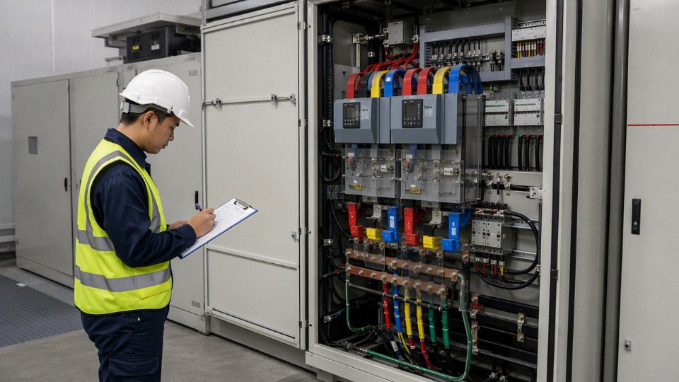
Different markets also use different reference frameworks. IEC language commonly treats systems up to 1,000 V AC as low voltage, while North American purchasing often revolves around NEC installation rules, UL/CSA listings, and 600 V or 1 kV cable ratings. ICEA and IEEE documents may appear in utility, industrial, and engineered cable specifications. BS and EN references show up often in Commonwealth, Middle East, European, and consultant-driven projects. None of these labels should be left implied.
| Reference framework | Typical procurement relevance | What the buyer must specify |
|---|---|---|
| IEC | International LV/MV voltage-class language, cable construction, testing references | Exact IEC standard edition or project standard that governs the cable |
| NEC | Installation acceptance in many North American-style projects | Installation article context, not just cable voltage rating |
| UL / CSA | Product listing, marking, and market acceptance | Required listing or certification mark, cable type, and voltage rating |
| ICEA | Common in North American industrial and utility cable specifications | Cable construction, insulation system, test expectations |
| IEEE | Often tied to testing, protection, and engineered power systems | Which IEEE document applies and whether it is mandatory or advisory |
| BS / EN | Common in UK, EU-linked, Middle East, and consultant specifications | Exact harmonized or national standard and fire-performance requirement |
| Project specification | Owner or EPC-specific rules that may override catalog assumptions | Revision number, approved vendor list, documentation package, and inspection points |
The commercial mechanism is simple: suppliers quote what they can defend against the written requirement. If the standard path is vague, they either add contingency cost, quote a conservative construction, or assume the lowest acceptable interpretation. All three create trouble. The first inflates the bid, the second may overload conduit fill or cable tray capacity, and the third can fail document review after the drums are already scheduled.
Certification and documentation should be listed in the inquiry, not requested after production. For 480 V cable and related equipment, the required package often includes:
- Type test reports for the relevant cable design, where applicable
- Routine test reports for the produced batch or drum set
- Factory test certificates or certificates of conformity
- Material declarations for conductor, insulation, sheath, armor, and jacket compounds
- Flame test records when the project specifies flame-retardant, low-smoke, or fire-performance cable
- RoHS or REACH declarations where the destination market or owner requires them
- Quality-management certificates, such as ISO-based system certificates where accepted by the buyer
- Packing lists showing drum number, cable type, size, length, gross weight, and net weight
- Marking samples or marking text for owner approval before mass production
Export details look minor until they stop a shipment or delay pulling cable. English cable marking may be mandatory for the installation contractor and inspector. Meter marking matters when the cable pulling plan, drum schedule, and as-built records are all written in metric units. Drum size should match unloading equipment, site roads, storage area, and maximum pulling setup; a drum that looks efficient in a container can be a nuisance if the site only has a small forklift and muddy access after rain. Destination climate and storage duration also affect packaging: tropical humidity, coastal salt air, desert temperature swing, and long outdoor storage all push the supplier toward better end sealing, wrapping, lagging, and moisture protection.
Direct substitution between 600 V, 1 kV, and medium-voltage cable constructions is one of the more expensive mistakes in this voltage range. A higher voltage-rated cable may be electrically acceptable in many cases, but it is not automatically interchangeable in the physical installation. It can change:
- Outside diameter
- Cable weight per meter
- Minimum bend radius
- Pulling tension and sidewall pressure
- Conduit fill
- Cable tray loading
- Gland, lug, and termination dimensions
- Heat dissipation assumptions
- Drum length and shipping cost
- Installed cost per circuit
The trade-off is not one-sided. A 1 kV cable may give a project team standardization margin across several low-voltage systems, especially on export jobs where future spares are hard to source. A 600 V cable may fit existing conduit, reduce weight, and lower delivered cost. The preferred choice flips when the installation envelope is fixed, the termination kits are already purchased, or the project specification demands a listed construction that only exists in one rating family. Medium-voltage cable should not be used as a casual “upgrade” for 480 V circuits unless the whole design checks out mechanically and commercially.
Bulk buyers can reduce this risk by standardizing the cable schedule before sending the RFQ. In practice, I like to see one controlled schedule with columns for:
- Voltage class and rated voltage
- Circuit service, such as motor feeder, MCC supply, transformer secondary, VFD output, lighting panel, or control power
- Conductor material and size
- Number of cores or conductors, including neutral and grounding conductor arrangement
- Insulation type
- Sheath or jacket type
- Flame rating or smoke requirement
- Armor, screen, or shielding requirement
- Color coding and core identification
- Installation method, such as tray, conduit, direct burial, duct bank, or indoor equipment wiring
- Certification package
- Packing length and drum requirement
- Destination country and document language
For a manufacturer like Jinda, the useful capability is not just producing cable; it is supporting this kind of project-level alignment before production starts. Jinda’s five production bases, large manufacturing footprint, integrated R&D, technical support, and export experience give procurement teams a practical route for long-run supply, multi-size schedules, documentation coordination, and repeat purchasing across international projects. The boundary is still the project specification: no supplier can correctly optimize cable construction, marking, testing documents, and packing until the buyer states the governing standard route and the actual 480 V system details.
Common misclassification risks
The common damage is not just a wrong label; it is wrong equipment, wrong work rules, and wrong purchasing language. Calling 480 V “medium voltage” can over-specify cable and accessories, while treating it as “just low voltage” can under-control shock, arc-flash, grounding, and fault-duty risks that are very much industrial-scale.
- Specifying medium-voltage cable for ordinary 480 V feeders
This is the expensive mistake I see in bid packages that were copied from a utility or campus distribution job. A normal 480 V motor feeder or panel feeder usually does not need 5 kV, 8 kV, or 15 kV cable unless a project standard, drive application, unusual transient condition, or installation rule specifically requires it.The mechanism is simple: higher-voltage cable insulation and shielding systems increase diameter, bending radius, termination complexity, and sometimes minimum reel size. That affects conduit fill, tray loading, pulling tension, gland selection, lug compatibility, and field labor. The buyer may think they bought “safer cable,” while the installer is fighting a cable that does not fit the MCC bucket, gland plate, or existing duct bank.
There are cases where a higher-rated cable is intentional, especially for severe VFD duty, long feeders, or harmonized plant inventory. But if the only reason is “480 V sounds like medium voltage,” the trade-off is usually poor: more cost and installation risk with no meaningful improvement in the actual 480 V circuit design.
Relaxing safety controls because it is low voltage
Low voltage does not mean low consequence. A 480 V switchboard, MCC, bus plug, or disconnect can deliver severe shock and arc-flash energy if the available fault current and clearing time are high.A 480 V three-phase system is normally low voltage by classification, but it can still present severe shock, arc-flash, and equipment-damage hazards.True
Voltage classification and hazard severity are different decisions. Hazard depends on exposure, grounding, available short-circuit current, protective-device clearing time, enclosure condition, work method, and maintenance state.
In practice, the dangerous jobs are often ordinary ones: tightening a loose starter lug, probing a live VFD input, replacing a bucket fuse after a fault, or opening a dusty disconnect with weak door interlocks. The label “low voltage” should never be used to skip lockout, arc-flash assessment, PPE selection, insulated tools, absence-of-voltage verification, or qualified-worker rules.
Confusing cable rated voltage with system voltage
A 1 kV rated cable on a 480 V system does not make the system “above 1 kV.” It means the cable insulation rating is suitable up to that rating under the applicable standard and installation conditions.This confusion causes bad procurement comparisons. One supplier quotes 600 V cable, another quotes 0.6/1 kV cable, and someone assumes the second offer is for a medium-voltage installation. The correct comparison requires the full standard, conductor class, insulation type, jacket or sheath, flame performance, certification, and test documentation.
Ignoring grounding configuration
A typical 480Y/277 V system has 480 V line-to-line and 277 V line-to-ground. A 480 V delta system may be ungrounded, high-resistance grounded, or corner-grounded, and each behaves differently during faults.This matters for insulation stress, ground-fault detection, protective-device operation, and maintenance troubleshooting. An ungrounded or high-resistance grounded system may continue operating during the first ground fault, which sounds attractive until the second fault lands on another phase. Corner-grounded delta can confuse technicians who expect all phase-to-ground readings to look like a wye system.
Failing to verify short-circuit current and equipment ratings
Voltage class does not prove interrupting rating. A 480 V breaker, fused switch, panelboard, busway, or MCC must be rated for the available fault current at its installation point.The path from transformer size and impedance to incident energy is not academic. A larger service transformer, parallel feeders, or a utility upgrade can raise fault current enough that old gear no longer has adequate SCCR or interrupting capacity. The cable may be perfectly selected as low voltage, while the equipment around it is unsafe to close after a fault.
Copying a medium-voltage specification into a 480 V plant project
A medium-voltage template can drag in shielded cable requirements, partial-discharge language, stress cones, MV termination kits, hipot routines, and documentation packages that do not belong on a standard 480 V feeder.The reverse problem also appears: the job gets bid with MV-style wording, then the site expects LV installation speed and LV accessory pricing. That mismatch shows up late, usually when the contractor asks whether the cable tray spacing, glands, test procedure, and spare terminations are actually required.
Accepting a vague supplier quotation
“Power cable” is not enough for a 480 V industrial circuit. A usable quotation should identify at least:
- voltage rating and applicable standard
- conductor material, size, stranding, and core count
- insulation and sheath or jacket material
- flame, oil, sunlight, or chemical resistance where required
- armor, screen, or grounding conductor arrangement if applicable
- certification marks or compliance documents
- routine test documentation and packaging details
- reel length tolerance and marking requirements
This is where procurement can prevent a week of site frustration with one clarification email. If the quote cannot tell you what will arrive on the reel, it is not ready for approval.
Overlooking special loads and environments
Some 480 V circuits are harder on cable than the voltage label suggests. Variable frequency drives can impose steep voltage rise times and reflected-wave stress, especially on long motor leads. Large motors bring high starting current and thermal cycling. Welders and nonlinear loads add heating, harmonics, and nuisance voltage-drop complaints. Outdoor runs, washdown zones, petrochemical areas, battery rooms, and corrosive process spaces may need jacket, armor, flame, oil, UV, or chemical resistance that a basic building wire does not provide.For 480 V projects, the safer procurement habit is to specify the actual electrical duty and installation environment, not just the voltage class. That conclusion stops holding only when the owner has a validated plant standard that intentionally over-specifies cable construction for maintainability, harsh service, or common spares—and even then, the accessories, terminations, and test requirements still need to match the 480 V system rather than a borrowed medium-voltage package.
Frequently asked questions
Is 480 V medium voltage?
No. A 480 V three-phase system is normally classified as low voltage, not medium voltage, under common industrial, cable-market, and IEC-style voltage classes.
That does not make it a “light-duty” voltage. A 480 V motor control center with a large transformer behind it can have enough available fault current to destroy gear, vaporize copper, and create a serious arc-flash exposure if the equipment is misapplied or poorly maintained.
A 480 V three-phase system is normally medium voltage.False
Under common North American and IEC voltage-class conventions, 480 V AC is normally treated as low voltage. Many industrial cable and utility markets begin medium-voltage categories above 1 kV, although exact wording depends on the governing standard and local practice.
Is 480 V considered high voltage?
In plant-floor speech, yes, people may call 480 V “high voltage” to separate it from 120 V control power, receptacle circuits, or small machine wiring. Formally, it is usually still low voltage.
That language gap causes trouble in purchasing. If a buyer writes “high-voltage cable for 480 V motor feeder,” one supplier may quote a heavy medium-voltage construction, another may ask for clarification, and a third may quote the correct 600 V or 1 kV industrial cable. Use the actual system voltage and cable rating instead of relying on the informal label.
What is 480Y/277 V?
480Y/277 V means a grounded wye three-phase system with 480 V measured line-to-line and 277 V measured from line to neutral. The “Y” tells you the transformer or system connection is wye, and the neutral point is commonly grounded.
In practice, 480 V serves three-phase loads such as motors, pumps, chillers, compressors, and large production equipment. The 277 V side is often used for lighting or other line-to-neutral loads where permitted by the electrical design. Do not assume every 480 V system has a usable neutral; a 480 V delta system behaves differently, especially under ground-fault conditions.
What voltage does medium voltage start at?
Many industrial and cable markets treat medium voltage as starting above 1 kV AC. Common medium-voltage cable classes then include ratings such as 5 kV, 8 kV, 15 kV, 25 kV, and 35 kV.
The exact boundary can vary by standard, utility practice, country, and equipment category. That is why a project specification should say something like “480Y/277 V, three-phase, 60 Hz, grounded wye, cable rated 600 V” rather than only “low voltage” or “medium voltage.” The voltage class is a useful shortcut, but the actual voltage and applicable standard control the purchase.
Can I use 600 V cable on a 480 V system?
Yes, properly selected 600 V cable is commonly used on 480 V industrial systems. The cable still has to match the application: conductor size, insulation type, temperature rating, ampacity, installation method, wet or dry location, tray or conduit use, flame requirement, oil or chemical exposure, and local code or project standard.
A common mistake is checking only “600 V” on the jacket and ignoring the rest. A 600 V cable suitable for dry indoor control wiring may not be acceptable for a wet outdoor feeder, a cable tray run in a process plant, a flexible motor connection, or an oil-exposed machine tool circuit. Voltage rating is only one line on the cable datasheet.
When would 1 kV cable be used for 480 V?
A 1 kV cable may be used on a 480 V system when the project standard, customer specification, export market, cable construction, or engineering margin calls for it. This is common in some IEC-based procurement packages where 0.6/1 kV cable is the normal low-voltage power cable category.
Typical reasons include:
- Standardizing cable inventories across several low-voltage systems.
- Meeting an EPC or end-user specification that calls for 0.6/1 kV cable.
- Matching IEC-style cable constructions rather than North American 600 V types.
- Satisfying documentation expectations for export projects.
- Using armored, fire-resistant, low-smoke, or special-sheath cables that are commercially built around a 1 kV rating.
- Providing margin where operating conditions are harsh, subject to engineering approval.
Do not treat 1 kV cable as a substitute for good design. It does not fix undersized conductors, poor terminations, overheated tray runs, incorrect grounding, or weak short-circuit protection.
Do 480 V cables need shielding?
Standard 480 V feeders usually do not need medium-voltage-style shielding. Most are installed with conventional low-voltage power cable in conduit, tray, armored construction, or other approved wiring methods.
There are cases where shielded cable makes sense, but the reason is usually electromagnetic behavior, not voltage class. Variable frequency drive circuits are the classic example. A VFD output cable may use symmetrical grounds, foil or braid shields, or special insulation to control common-mode current, electrical noise, reflected-wave stress, and bearing-current issues. That is a different design problem from the semiconductive insulation shields used on true medium-voltage cable.
If the cable serves a drive, servo system, instrumentation-heavy machine, or electrically noisy process line, ask for the drive manufacturer’s cable recommendations and verify grounding details. A shield that is terminated badly can become a nuisance instead of a cure.
Does 480 V require medium-voltage terminations?
No. Standard 480 V low-voltage cable normally uses low-voltage lugs, glands, connectors, ferrules, heat-shrink boots where needed, and termination practices suited to the equipment and cable type. It does not normally require medium-voltage stress cones, premolded elbows, or insulation-shield cutback procedures.
The workmanship still matters. Loose lugs, over-stripped insulation, wrong crimp dies, poor gland sealing, and unlanded grounding conductors cause plenty of 480 V failures. I have seen more downtime from ordinary loose terminations than from exotic insulation problems at this voltage class. Torque values, conductor preparation, bend radius, phase spacing, enclosure rating, and heat dissipation are the things to check against the equipment manual and cable documentation.
Is 480 V more dangerous than 240 V?
Often, yes, especially in industrial systems with large transformers, short cable runs, and high available fault current. The shock voltage is higher, and the energy available during a fault can be much greater than in a small 240 V circuit.
The actual hazard depends on the whole system:
- Transformer size and impedance.
- Available short-circuit current at the equipment.
- Protective device type, settings, and clearing time.
- Grounding method.
- Enclosure condition and door interlocks.
- Working distance and task type.
- Maintenance history, including loose hardware and contamination.
- Whether the equipment has been arc-flash assessed and labeled where required.
A small 480 V control panel and a large 480 V switchboard are not the same risk. Treat the label voltage as the starting point, then verify the available fault current, protection, and required safe-work procedure.
What information should I give a cable supplier?
Give the supplier enough information to select the cable, not just quote the lowest unit price. For a 480 V industrial circuit, provide:
- System voltage, such as 480 V, 480Y/277 V, or 480 V delta.
- Phase and frequency, for example three-phase, 60 Hz.
- Grounding method, including grounded wye, corner-grounded delta, high-resistance grounding, or ungrounded system.
- Load type, such as motor, feeder, VFD output, transformer secondary, heater bank, or distribution panel.
- Load current, starting current if relevant, and expected duty cycle.
- Conductor material, usually copper or aluminum.
- Required conductor size, or the design current and allowable voltage drop if sizing is expected.
- Number of conductors, grounding conductor requirement, and neutral requirement.
- Installation method: conduit, tray, direct burial, duct bank, armored cable, flexible connection, or festoon/reeling service.
- Ambient temperature and grouping conditions for ampacity derating.
- Indoor, outdoor, wet, oily, UV-exposed, corrosive, marine, mining, or other environmental exposure.
- Required insulation and sheath type, if already specified.
- Applicable standard, project specification, or certification requirement.
- Flame, smoke, halogen, fire-resistance, or circuit-integrity requirement.
- Armor, screen, shield, or braid requirement, especially for VFD or EMC-sensitive installations.
- Approximate length, drum length limits, and pulling constraints.
- Jacket marking, test report, packing, inspection, and documentation requirements.
If the application involves VFDs, outdoor chemical exposure, direct burial, high ambient temperature, or export certification, say so early. Those details change the cable construction and price far more than the difference between calling the system “low voltage” and “medium voltage.”
Your voltage-class verification step
Use this sequence before issuing the RFQ, purchase order, or cable schedule revision. If the circuit is a typical 480 V industrial feeder, motor circuit, MCC supply, panel feeder, or 480Y/277 V distribution circuit, the buyer should normally specify a low-voltage cable system, not a medium-voltage cable system.
A typical 480 V AC industrial circuit is normally treated as low voltage for cable and equipment classification, but it still requires industrial-grade shock, arc-flash, short-circuit, and installation controls.True
Common IEC conventions place low voltage up to 1,000 V AC, and many North American cable and utility categories treat medium voltage as beginning above 1 kV. The hazard level is still serious because available fault current, grounding, enclosure condition, and protection settings drive incident energy and equipment damage.
1. Verify the electrical system before naming the cable
Do not start with the words “low voltage” or “medium voltage.” Start with the system data. The label comes after the circuit is understood.
Confirm these items in order:
- Nominal voltage
- 480 V line-to-line?
- 480Y/277 V?
- 480 V delta?
- 480 V AC from a transformer secondary?
- 480 V DC from a battery, drive DC bus, rectifier, or solar-related system?
- Maximum operating voltage
- Normal utility tolerance may push the actual voltage above the nameplate value.
- Some specifications require cable selection by maximum system voltage, not just nominal voltage.
- A 480 V system will commonly use 600 V, 1 kV, or in some cases 2 kV-rated cable depending on the applicable standard, installation, and project specification.
- AC or DC
- AC cable ratings cannot always be copied directly into DC service without review.
- DC systems can stress insulation differently, especially where polarity, grounding, switching, and thermal loading are not conventional.
- Phase arrangement
- Three-phase three-wire.
- Three-phase four-wire.
- Single-phase derived from a 480Y/277 V system.
- Separately derived transformer secondary.
- Drive output cable from a VFD, which is not the same electrical environment as a clean sinusoidal feeder.
- Grounding method
- Solidly grounded wye.
- Corner-grounded delta.
- Ungrounded delta.
- Resistance-grounded system.
- High-leg delta where still present in older plants.
Grounding is not paperwork detail. It changes fault behavior, overvoltage exposure, protection operation, and sometimes the insulation level expected by the project engineer. A solidly grounded 480Y/277 V feeder feeding a lighting panel is a very different animal from an ungrounded 480 V delta circuit feeding a critical process line where the first ground fault may not trip immediately.
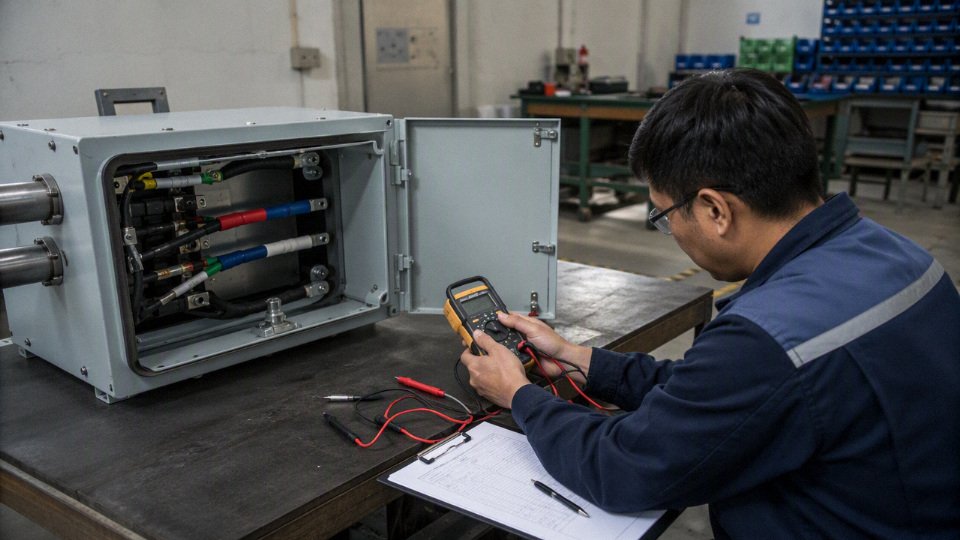
2. Lock the governing standard before comparing supplier offers
A 480 V cable quotation is only comparable when every bidder is working to the same standard and the same construction expectation. In practice, I have seen purchasing teams compare a 600 V building wire offer, a 1 kV IEC power cable offer, and a shielded VFD cable offer as if they were interchangeable because all three were “for 480 V.” They are not interchangeable.
Confirm which framework controls the purchase:
| Standard or specification family | Why it matters for a 480 V purchase |
|---|---|
| NEC / NFPA 70 project basis | Drives installation method, ampacity conditions, raceway or tray use, conductor types, and field acceptance expectations in many U.S.-style projects. |
| UL-listed cable requirements | Often required by U.S. inspectors, OEM panels, industrial owners, and insurance-driven specifications. |
| CSA requirements | Commonly required for Canadian projects and some North American equipment packages. |
| IEC cable standards | Common for international industrial, utility, infrastructure, and export projects; voltage naming may use 0.6/1 kV rather than 600 V language. |
| ICEA / IEEE references | Often appear in North American utility, industrial, and engineered project cable specifications. |
| EN or BS standards | Relevant in European, Middle East, African, and Commonwealth-influenced project documents. |
| Project-specific specification | May override normal catalog selection with special flame, smoke, armor, sheath, marking, testing, or documentation rules. |
The trade-off is commercial as much as technical. If you specify too loosely, you may receive a cheap cable that fits the voltage but fails the installation environment, inspection requirement, or owner standard. If you specify too rigidly, you may force a nonstandard construction, longer manufacturing lead time, and higher cost without improving reliability.
The preferred choice flips when the project has a mandatory compliance route. For example, an export skid built for a U.S. site may need UL-recognized or UL-listed cable even if the equipment was fabricated elsewhere. A mining, marine, transit, offshore, tunnel, or data center project may have additional flame, smoke, halogen, armor, tray, or certification requirements that matter more than the basic 480 V classification.
3. Decide the cable construction from duty, not voltage class alone
For a normal 480 V industrial circuit, the practical cable construction usually starts as a low-voltage power cable selection. The engineering work is in choosing the right conductor, insulation, jacket, installation rating, and documentation package for the duty cycle and site conditions.
Define these construction items clearly:
- Conductor material
- Copper where compact termination, high conductivity, and familiar maintenance practice are priorities.
- Aluminum where larger feeders, weight, and cost reduction justify larger conductor size and compatible terminations.
- Confirm lug material, oxide inhibitor practice, torque method, and retorque policy if aluminum is used. A loose aluminum termination in a hot MCC bucket is not a theoretical failure mode; it is a maintenance call waiting to happen.
- Conductor size
- Based on continuous current, derating, ambient temperature, grouping, voltage drop, short-circuit withstand, and termination temperature rating.
- Do not size only from motor full-load current if the route runs through a hot cable tray above a process line or through a packed conduit bank.
- Insulation type and voltage rating
- 600 V, 1 kV, or 2 kV selections may all appear around 480 V industrial work depending on market and duty.
- Drives, long motor leads, high switching frequency, and reflected-wave concerns may justify insulation systems or cable constructions beyond a basic feeder cable.
- Outer sheath or jacket
- Match the sheath to oil, water, sunlight, abrasion, low temperature, chemical exposure, and installation handling.
- A cable that looks good on a datasheet can age quickly if the jacket sits in oily tray dust under a compressor mezzanine.
- Armor or mechanical protection
- Consider armor where cable is exposed, buried, routed through rough industrial areas, or where project specifications require it.
- Armor can improve mechanical protection but adds weight, bending stiffness, gland requirements, and pulling difficulty.
- Shielding
- Standard 480 V feeders usually do not need medium-voltage-style shielding.
- Shielded constructions may be required for VFD motor leads, electromagnetic compatibility, instrumentation adjacency, or owner standards.
- Flame, smoke, and toxicity performance
- Confirm tray flame, low-smoke, halogen-free, fire-resistant, or circuit-integrity requirements where applicable.
- These are not interchangeable terms; each has its own test basis and project meaning.
- Temperature rating
- Check both conductor insulation rating and termination rating.
- A 90°C cable may still be limited by 75°C equipment terminals in the ampacity calculation.
- Marking requirements
- Voltage rating, standard reference, conductor size, core count, manufacturer identification, batch traceability, and meter marking may be required.
- Destination-market language and marking rules should be confirmed before production, not after the drums arrive at site.
The mechanism is straightforward: current creates heat, heat accelerates insulation aging, and the actual heat rise depends on installation conditions as much as conductor size. A cable in open tray with moving air behaves differently from the same cable pulled into a crowded steel conduit with other loaded circuits. That is why a 480 V cable that is electrically “low voltage” can still fail early if the ampacity, grouping, ambient temperature, and termination constraints are treated casually.
4. Check the cable against the whole installation
A good cable selection can still become a bad installation if it does not fit the equipment and route. This is where procurement needs input from engineering, maintenance, and the installer, not only the catalog page.
Check compatibility with:
- Switchgear and MCC terminals
- Lug size.
- Conductor material approval.
- Number of conductors per phase.
- Maximum insulation diameter.
- Terminal temperature rating.
- Circuit breakers, fuses, and protective relays
- Continuous current rating.
- Short-circuit rating.
- Let-through energy.
- Ground-fault protection.
- Coordination with upstream and downstream devices.
- Motors and drives
- Across-the-line starter or VFD output.
- Motor lead length.
- Carrier frequency where applicable.
- Need for symmetrical grounds, shield, or special drive cable design.
- Tray, conduit, duct bank, or direct-buried route
- Fill percentage.
- Bend radius.
- Pulling tension.
- Sidewall pressure.
- Support spacing.
- Moisture and drainage.
- Cable drum planning
- Pull lengths.
- Drum weight.
- Site handling equipment.
- Laydown space.
- Sequencing by installation area.
- Spare length policy.
- Termination hardware
- Glands.
- Lugs.
- Heat-shrink or cold-shrink parts where used.
- Grounding kits for shielded cable.
- Identification tags and ferrules.
- Testing plan
- Continuity.
- Insulation resistance.
- Phasing.
- Torque verification.
- Any project-specified withstand or acceptance test.
- Test voltage and method must match the cable type, voltage rating, standard, and equipment connected.
- Spare inventory
- Critical feeders.
- Long-lead constructions.
- Site-standard conductor sizes.
- Repair joints and termination kits if used by the maintenance team.
One practical warning: do not order cable solely by cross-sectional area or AWG size and voltage rating. The installer may later discover that the bend radius does not work in the MCC room, the gland plate cannot accept the armor, or the drum length creates an extra joint in a wet trench. Those mistakes are rarely expensive on the purchase order; they become expensive during outage work.
5. Require documentary proof from the supplier
For industrial procurement, the correct cable is not just the cable itself. It is the cable plus the evidence package that lets the owner, contractor, inspector, and maintenance team accept it.
Ask for the required documents before order placement:
- Product data sheet
- Construction.
- Voltage rating.
- Conductor size and class.
- Insulation and sheath materials.
- Dimensional and weight data.
- Applicable standards.
- Standards compliance statement
- Identify the exact standard and edition where possible.
- Avoid vague wording such as “international standard cable” without a named basis.
- Routine test records
- Electrical and dimensional checks normally required by the governing cable standard.
- Confirm what is supplied as standard and what requires special request.
- Type test references where applicable
- Especially for project specifications that require flame, fire, oil resistance, low smoke, mechanical, or special performance evidence.
- Do not assume every catalog construction has every possible type test.
- Quality certificates
- Manufacturer quality system documentation if required by the project.
- Inspection and release documents required by the buyer.
- Packing details
- Drum size.
- Drum weight.
- Cable length per drum.
- Protection method.
- Shipping marks.
- Handling instructions.
- Drum numbers and traceability
- Batch or production identification.
- Length allocation by cable tag where the project needs it.
- Traceability between test records, drums, and packing list.
This is where overbuying and under-specifying both show up. Buying medium-voltage cable for an ordinary 480 V feeder can add unnecessary cost, stiffness, termination complexity, shielding work, and delivery time. Treating 480 V as “just low voltage,” on the other hand, can lead to poor flame performance, wrong jacket material, inadequate short-circuit withstand, bad VFD behavior, or missing documentation that delays commissioning.
The normal conclusion stops holding when the actual system voltage, owner specification, regulatory path, or application duty demands something beyond a standard low-voltage construction. That does not automatically make the circuit medium voltage. It means the 480 V cable specification needs to be engineered rather than guessed.
Send the right information for a clean 480 V cable review
For a typical 480 V industrial circuit, start from a low-voltage cable specification and then build up the construction around current, grounding, protection, installation, environment, and the governing standard. That approach avoids the two costly extremes: paying for medium-voltage construction where it adds no value, or buying a low-duty cable that cannot survive the plant.
To help Jinda verify the correct low-voltage cable specification and prepare a quotation package, send:
- Single-line diagram.
- Cable schedule.
- Load list, including motors, drives, transformers, panels, and major feeders.
- Nominal voltage and maximum operating voltage.
- AC or DC service.
- Phase arrangement and grounding method.
- Continuous current and expected load profile.
- Available fault-current level if known.
- Protective-device type and rating.
- Installation method: tray, conduit, duct bank, direct burial, flexible connection, or equipment internal wiring.
- Ambient temperature, moisture, sunlight, oil, chemical, abrasion, and flame-performance requirements.
- Required standard or project specification: IEC, NEC, UL, CSA, ICEA, IEEE, EN, BS, or owner specification.
- Destination market and inspection requirements.
- Required markings, packing, drum length limits, and documentation needs.
Jinda’s technical and sales support team can review those details against available low-voltage cable constructions, clarify the required standard language, and prepare a quotation package for international cable procurement, bulk supply, or project purchasing. If the information is incomplete, send the single-line diagram and cable schedule first; those two documents usually expose the questions that matter before anyone wastes time pricing the wrong cable.