Specify the wrong cable type on a procurement order — say, a rubber-insulated flexible instead of a XLPE-insulated power cable — and the consequences run deeper than a simple swap-out. You’re looking at potential re-pulls through conduit, derating calculations that have to be redone, possible non-compliance with the site’s governing standard (IEC 60502, UL 44, or whichever applies), and in the worst case, an insulation failure that takes a production line down for days rather than hours. The financial hit compounds fast: lost output, emergency freight on replacement stock, and the labor to redo terminations nobody budgeted for.
The three main types of cable wire used across industrial, commercial, and infrastructure projects are power cables, control and instrumentation cables, and flexible/specialty cables. Power cables carry load current between sources and equipment; control cables transmit signals and switching commands; flexible cables handle repeated mechanical movement or harsh environments. Each category covers a range of conductor materials, insulation types, and construction standards.
What makes this more than a simple taxonomy is how much the choice within each category actually matters — copper versus aluminum conductors alone shifts your current-carrying capacity by roughly 40% for the same cross-section, which cascades directly into conduit sizing, voltage drop, and the weight your cable tray was specified to support. The global wire and cable market was sitting around USD 225 billion in 2023 and is tracking toward USD 300 billion by 2030, which tells you something about how many of these decisions are being made every day, often under time pressure, often by people working from an incomplete spec sheet. Getting the category right is the starting point.
Power Cables: Construction Layers, Voltage Classes, and Load-Carrying Mechanics
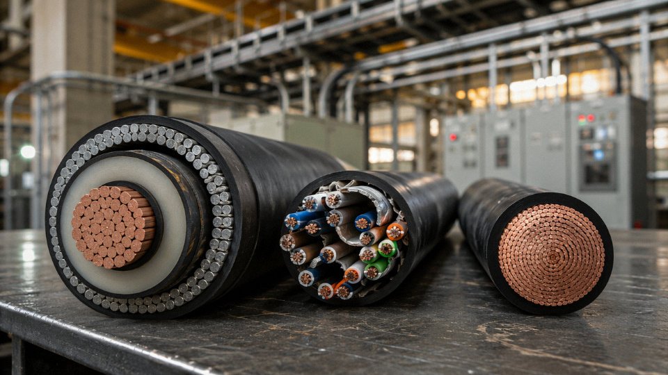
Power cables are the backbone of virtually every electrical infrastructure project, from a 400 V distribution board feeding a factory floor to a 220 kV underground transmission link running beneath a city. Getting the construction right isn’t an academic exercise — the wrong insulation system at the wrong voltage class will fail, and that failure usually doesn’t announce itself politely. It shows up as a ground fault mid-shift, a transformer trip, or in a worst case, a fire.
The Layered Anatomy — What Each Layer Actually Does
A well-built power cable is a stack of engineering decisions, not just a wire with some plastic around it.
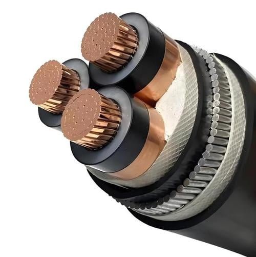
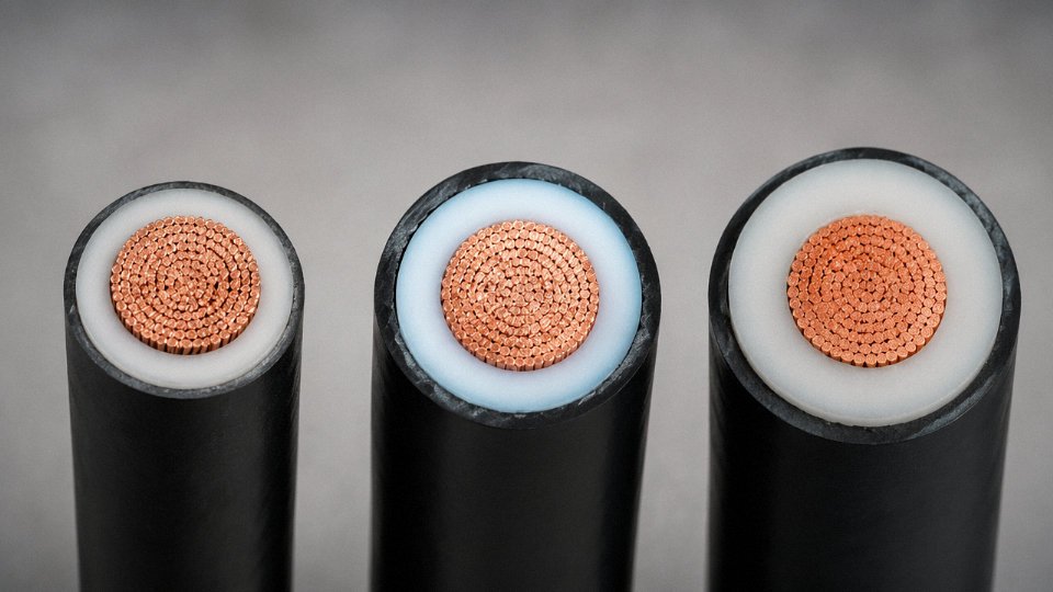
The conductor sits at the center. Stranded construction is the norm for anything above a few millimeters cross-section because it improves flexibility and reduces mechanical fatigue during installation — solid conductors are mostly confined to small building wire or certain utility distribution applications. Copper dominates where space is tight and ampacity-per-millimeter matters most. Aluminum wins where weight and raw material cost outweigh the penalty in conductor cross-section. Copper’s resistivity runs at roughly 1.72 × 10⁻⁸ Ω·m versus aluminum’s 2.82 × 10⁻⁸ Ω·m, meaning copper can carry around 40% more current through the same cross-sectional area. In practice, that means you’d typically need an aluminum conductor roughly 1.6× larger in cross-section to match a copper conductor’s ampacity — which adds diameter, changes conduit sizing, and affects termination hardware. Aluminum cables weigh roughly 70% less per meter at equivalent ampacity compared to copper, depending on conductor class and stranding. For long overhead or large-bore underground runs, that weight advantage is real money in trenching, pulling, and support structures.
Primary insulation wraps the conductor and carries the electrical stress. XLPE (cross-linked polyethylene) is now the dominant choice for MV and HV cables — it handles continuous operating temperatures up to 90 °C, has excellent dielectric properties, and resists water treeing better than older PVC systems. PVC insulation still appears in LV building cables and cost-sensitive short-run industrial wiring, but its maximum operating temperature of around 70 °C limits ampacity at equivalent cross-sections. EPR (ethylene propylene rubber) earns its place in flexible or cold-weather installations because it stays pliable at low temperatures and tolerates thermal cycling better than XLPE — you’ll see it in offshore platforms and mining equipment fairly often.
A metallic screen or shield sits outside the insulation in cables rated above roughly 3.6 kV. Its job is to confine the electric field within the insulation layer and provide a return path for fault current. Without it, you get partial discharge at the conductor surface and accelerated insulation degradation. Screen design — copper tape, copper wire, or a combination — is specified based on fault current levels and the cable’s capacitive charging current.
The inner sheath (usually PVC or PE) protects the screen and bedding layers during armoring. Armor comes next: steel wire armor (SWA) for direct burial where rodent damage or mechanical impact is a real risk, aluminum wire armor (AWA) on single-core cables where steel would create eddy-current losses, and wire braid on flexible industrial cables. The outer jacket is the final environmental barrier — UV-resistant PE for outdoor runs, low-smoke zero-halogen (LSZH) compound for tunnels and confined spaces where toxic smoke is a life-safety concern.
Voltage Class Logic — How the Spec Scales
Insulation thickness, screen design, and testing severity all climb with voltage class. IEC 60502-1 covers LV and MV cables up to 30 kV; IEC 60502-2 extends into the upper MV range; IEC 60840 governs HV cables from 30 kV up through 150 kV and beyond.
| Voltage Class | Typical Voltage Range | Primary Insulation | Common Armor Type | Typical Application | Key Standard |
|---|---|---|---|---|---|
| LV | Up to 1 kV | PVC or XLPE | SWA or unarmored | Building services, plant feeders | IEC 60502-1 |
| MV | 1–36 kV | XLPE or EPR | SWA or AWA | Underground distribution, renewables | IEC 60502-2 |
| HV | 36–150 kV | XLPE | Wire screen + HDPE jacket | Transmission links, grid substations | IEC 60840 |
| EHV | Above 150 kV | XLPE (thick wall) | Corrugated aluminum sheath | National grid, subsea export | IEC 62067 |
Insulation wall thickness at LV might be 0.7–1.0 mm on a small conductor; at 66 kV it’s typically in the 13–18 mm range, depending on conductor size and the cable’s rated voltage factor. Testing at HV and EHV involves type tests — partial discharge, tan-delta, impulse withstand — that LV cables never see.
Where Each Construction Variant Lives
Underground urban distribution grids almost universally use XLPE-insulated, SWA-armored, PVC-jacketed cables in the MV range — they’re direct-buried, and the armor takes the mechanical abuse from backfill compaction and future excavation activity. Renewable energy installations, particularly large solar farms, run MV collector cables in the 6–35 kV range between inverter stations and the main substation; these often see a lot of pulling through conduit, so installer-friendly outer jackets and controlled outer diameters matter. Offshore wind introduces subsea power cables — a specialized construction with lead or corrugated copper water barriers and high-tensile armor layers capable of handling the dynamic bending stresses of cable-lay vessels. Industrial plant feeders in steel mills or chemical plants regularly demand LSZH jackets and, in some zones, fire-resistant or fire-retardant constructions per IEC 60332.
Copper conductors carry roughly 40% more current per unit cross-section than aluminum conductors of the same dimensions.True
This follows directly from the resistivity ratio: copper at 1.72 × 10⁻⁸ Ω·m versus aluminum at 2.82 × 10⁻⁸ Ω·m, giving aluminum roughly 64% higher resistance per unit length and cross-section, which requires a larger conductor to achieve equivalent ampacity.
Jinda’s power cable range covers XLPE-insulated armored cables for MV grid and renewable energy projects, LV armored distribution cables, and flexible industrial power cables designed for machinery with frequent movement cycles. Export compliance spans IEC 60502, BS 6346, and AS/NZS 5000 series, with test reports available for procurement teams working in regulated markets. For projects requiring a specific voltage class construction, conductor material trade-off analysis, or quantity-based specification support, direct engagement with Jinda’s technical team early in the procurement cycle saves the back-and-forth that typically delays project schedules by weeks.
Control and Instrumentation Cables: Signal Integrity, Shielding Configurations, and Industrial Automation Roles
A lot of engineers treat control and instrumentation cables as one product category. In a distributor catalog they often sit on the same shelf. On a large process plant, though, conflating them creates real problems — and understanding the distinction is the first step to specifying correctly.
What Separates Control Cables from Instrumentation Cables
Control cables carry switching signals and low-power command circuits: the 24 V DC signal that energizes a motor starter contactor, the 110 V AC command to a solenoid valve, the interlock wire running between a PLC output card and a relay. Current levels are modest but not trivial — typically in the range of a few hundred milliamps up to a few amps depending on the load — and the main concern is reliable continuity and voltage withstand, not microvolt accuracy.
Instrumentation cables are different in a fundamental way. They carry analog measurement signals from field transmitters and sensors back to a DCS or SCADA system: a 4–20 mA loop from a pressure transmitter, a millivolt-level thermocouple output, a 0–10 V signal from a flow meter. The signal energy is tiny, and any noise that couples onto that circuit shows up as a measurement error. On a custody-transfer flow measurement or a reactor temperature loop, that error has real consequences — process upsets, false alarms, or regulatory non-compliance. This is why precision projects specify them separately, even when the budget pressure is to consolidate.
Shielding: The Core Engineering Decision
Shielding is what makes an instrumentation cable an instrumentation cable. The choice of shield configuration depends on the interference environment and the signal type.
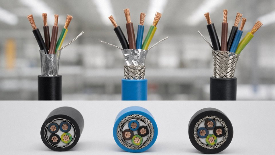
Foil shields (aluminized polyester or aluminum-polyester laminate with a drain wire) are effective against electrostatic, capacitively coupled noise. In a modern DCS environment with variable-frequency drives nearby, this is usually your dominant interference source. Foil gives you close to 100% optical coverage and works well up to moderate frequencies.
Braided shields handle magnetically induced noise better — relevant when the cable runs parallel to power feeders for extended distances, which happens constantly in the real world despite what the cable separation drawings say. Braid coverage typically runs 85–95%, and it adds mechanical robustness. The trade-off is cost and diameter.
Individually shielded pairs with an overall shield (often written as IS/OS) is the configuration you want for multi-pair instrumentation cables where crosstalk between pairs matters as much as external interference. Each pair gets its own foil, the whole assembly gets an overall braid or foil, and there’s a common drain wire. This is standard practice for analog multi-loop instrumentation cables on offshore platforms and large power plant DCS installations.
Shield grounding matters as much as the shield itself. A foil shield grounded at both ends in a high-frequency environment can become an interference antenna rather than a barrier. Single-point grounding at the control-room end is typical for analog DC loops.
Conductor Geometry and Why Twisting Is Non-Negotiable
Instrumentation cables use twisted pairs (or twisted triples for three-wire RTD circuits). The twisting — with a defined, controlled lay length — causes equal and opposite noise voltages to be induced on the two conductors simultaneously, so they cancel in the differential receiver at the other end. Reduce the lay length and you improve common-mode rejection; skip the twisting entirely and a 4–20 mA loop running near a VFD can pick up enough noise to make a flow reading jitter by several percent of span.
Multi-pair construction goes from 2 pairs up to 61 pairs in a single cable, which keeps tray fill manageable on large installations. Multi-core configurations (individual conductors rather than pairs) are used for control circuits where pairing is irrelevant.
Individually shielded twisted pairs significantly reduce inter-pair crosstalk compared to unshielded twisted pairs in multi-pair instrumentation cablesTrue
Crosstalk in multi-pair cables is a function of capacitive and inductive coupling between adjacent pairs. Individual foil shields provide a physical barrier that interrupts these coupling paths, which is well-documented in IEC 60544 and consistent with standard differential signaling theory.
Jacket and Insulation: Matching the Process Environment
The insulation and jacket choice depends on the physical environment, not just the voltage rating — and this is an area where cheap substitutions cause expensive failures.
LSZH (low-smoke zero-halogen) compounds are mandatory on offshore platforms, in tunnels, and on naval vessels where evacuation routes must stay clear and halogen-acid gases from burning PVC would damage electronics or injure personnel. Oil-resistant PVC (typically compound type TM2 or TM3 under IEC classifications) is the practical choice for petrochemical plants where the cable inevitably gets splashed. Silicone-insulated or PTFE-insulated cables are used in high-temperature zones — near furnace walls, in engine rooms, in glass-plant environments where ambient temperatures routinely exceed 90–100 °C. PTFE in particular handles continuous service up to around 200 °C and doesn’t absorb moisture, which matters for impedance stability in high-precision measurement circuits.
Armoring and Installation Context
In a modern cable tray inside a well-designed control building, armoring adds cost and installation difficulty without adding much value. Unarmored, overall-shielded instrumentation cable on properly supported ladder tray is the right call.
Outside that environment, it changes quickly. Direct-buried instrumentation cables for field junction box runs need steel wire armor (SWA) for rodent resistance and mechanical protection during backfill. Where weight matters — on cable trays on an offshore module or a floating production unit — corrugated aluminum armor is lighter than SWA and still provides adequate mechanical protection.
Standards Compliance in Practice
BS 5308 Part 1 (PVC insulated) and Part 2 (LSZH insulated) are the dominant international references for instrumentation cables, widely specified by EPC contractors on oil and gas projects regardless of where in the world the plant is being built. IEC 60332 fire performance requirements apply to both the instrumentation and control cable categories and are increasingly written into project specifications as a baseline, not an optional upgrade.
Jinda’s instrumentation cable range covers multi-pair constructions from 2 pairs through 61 pairs, with individually shielded, overall shielded, and IS/OS configurations available, compliant with BS 5308 Part 1 and Part 2. The lineup addresses oil and gas field instrumentation, power plant DCS backbones, and water treatment SCADA systems — applications where multi-core count, consistent lay length control, and shield continuity over the full cable run are non-negotiable.
Communication and Data Cables: From Structured Cabling to Fiber Optic Backbone Networks
Communication and data cables occupy a genuinely separate category — not just a marketing subdivision. Where power cables are rated by ampacity and voltage class, and control cables by signal level and shielding configuration, communication cables are judged by bandwidth, attenuation per unit length, return loss, near-end crosstalk (NEXT), and propagation delay. They carry information, not energy. The frequencies involved run from a few MHz for basic Ethernet up into the GHz range for Cat8 or RF coaxial applications, and at those frequencies the physics of conductor geometry, dielectric constant, and shielding architecture matter far more than conductor cross-section.
Copper Structured Cabling: The Cat5e-to-Cat8 Progression
The twisted-pair cable evolution follows a consistent logic: tighter twists, larger conductors, more aggressive shielding, and stricter geometric tolerances allow each successive category to push higher bandwidth over the same 100-meter channel distance defined by TIA-568 and ISO/IEC 11801.
Cat5e handles 1 Gbps at 100 m and remains the floor of anything worth installing today. Cat6 achieves the same 1 Gbps link speed but with a better noise margin — useful in environments with dense cable bundles where alien crosstalk accumulates. The real inflection point is Cat6A: 10 Gbps over 100 m, achieved by increasing conductor diameter to roughly 23 AWG, adding either U/FTP (individual pair foil) or F/UTP (overall foil) shielding, and tightening the twist pitch tolerance. The cable gets noticeably stiffer and heavier as a result — plan for larger conduit fill and more careful bend radius management during installation.
Cat7 and Cat8 push into 25–40 Gbps territory for short runs, primarily in data center top-of-rack and server-to-switch applications. Cat8 runs to 30 m per channel (Cat8.1) or 40 m (Cat8.2), uses S/FTP construction with individually shielded pairs, and requires proper grounding at both ends — skip that and the shield picks up noise rather than rejecting it.
Coaxial Cable: Where It Still Makes Sense
Coaxial construction — center conductor, solid or foam polyethylene dielectric, braided or foil-plus-braid outer shield, PVC or PE jacket — delivers a controlled, consistent impedance (typically 50 Ω for RF/antenna work, 75 Ω for CATV and CCTV) that twisted-pair cannot match at high RF frequencies. CATV trunk distribution, CCTV surveillance analog feeds, antenna runs for cellular or broadcast equipment, and any legacy industrial Ethernet installation still running 10BASE2 are the realistic applications today. In new structured cabling projects, coaxial rarely appears. In RF, broadcast, and outdoor surveillance infrastructure, it remains the sensible choice.
Fiber Optic Cables: Bandwidth Without Distance Compromise
Single-mode fiber (OS1/OS2, 9/125 µm core) is the long-distance workhorse. With appropriate transceivers — DWDM systems in particular — runs of 40–80 km are achievable without active amplification, depending on fiber quality, connector cleanliness, and splice count. Multimode fiber (OM3/OM4/OM5, 50/125 µm) targets shorter campus and data center links: OM4 supports 100 Gbps over roughly 150 m, and OM5 pushes toward 400 Gbps applications by supporting shortwave division multiplexing across a wider wavelength window.
Construction choice tracks the deployment environment. Tight-buffered fiber suits indoor runs and patch panels — the buffer coating bonds directly to the fiber, making termination straightforward. Loose-tube construction protects fibers inside gel-filled tubes that absorb mechanical stress and temperature-driven expansion; it’s the standard for outdoor direct-burial and aerial plant. Ribbon fiber, where 12 or more fibers are bonded into a flat array, allows mass fusion splicing and is increasingly specified for high-fiber-count backbone conduits where splice time drives project cost.
Fiber optic cable is completely immune to electromagnetic interference.False
Optical fiber carries light rather than electrical current, which makes it highly resistant to EMI — but the electronic transceivers at each end remain susceptible to electrical noise and surge events. The fiber itself is immune; the system is not entirely so.
Hybrid and Composite Cables
One practical trend worth noting: hybrid cables that combine optical fibers and copper power conductors inside a single jacket. Smart building systems, EV charging stations, and industrial IoT edge nodes increasingly need both data connectivity and a local power feed routed to the same endpoint. Pulling one hybrid cable instead of two separate cables cuts conduit usage, labor time, and long-term maintenance complexity. In practice, the tradeoff is that replacing or upgrading either element means replacing the entire run.
Jinda supplies armored fiber optic cables — including direct-burial and aerial constructions with steel wire or steel tape armor — and structured cabling solutions for telecommunications infrastructure and industrial LAN deployments across export markets. For project teams specifying high-fiber-count backbone networks or hybrid power-data runs for smart facility or EV infrastructure projects, discussing construction specifics early in the design phase avoids the usual last-minute substitution headaches.
Side-by-Side Comparison: Selecting the Right Type Based on Voltage, Environment, Distance, and Signal Type
Most specification errors happen not because an engineer doesn’t understand cables, but because the selection process gets compressed — a procurement manager picks a familiar product, or someone reuses a cable schedule from a previous project with a different environment. The table below consolidates the three types into a single reference. Use it alongside the flowchart logic that follows.
Comprehensive Comparison Table
| Parameter | Power Cable | Control & Instrumentation Cable | Communication & Data Cable |
|---|---|---|---|
| Primary function | Carry electrical energy to loads | Transmit low-level signals, control commands | Carry data, voice, structured network traffic |
| Typical voltage / current range | LV: up to 1 kV; MV: 1–35 kV; HV/EHV: 66 kV+ / tens to hundreds of amps | Typically 300–600 V AC; signal levels often millivolts to 24 V DC; <1 A | Cat cabling: <100 V; fiber: no electrical voltage; coax: varies by application |
| Conductor material options | Copper or aluminum; aluminum increasingly common above 70 mm² for cost | Copper almost exclusively; aluminum rarely justified at small cross-sections | Copper (Cat/coax); glass or plastic fiber (fiber optic) |
| Insulation system | XLPE or EPR preferred for MV/HV; PVC acceptable for dry LV only | PVC, XLPE, or LSZH; EPR in high-flex mobile applications | Polyethylene, LSZH, PTFE for high-frequency; fiber uses tight or loose buffer |
| Shielding requirement | Metallic screen on MV and above; generally none on LV power | Individual pair or overall foil/braid shield typically required; unshielded versions exist only for very benign environments | Coax is inherently shielded; Cat cables unshielded (UTP) or shielded (STP/FTP); fiber inherently immune to EMI |
| Armor options | SWA, AWA, DSTA depending on mechanical risk and whether aluminum is acceptable | Steel wire or tape armor for direct buried; many plant installations use unarmored in conduit | Armored fiber (rodent/crush protection); Cat rarely armored outside direct burial |
| Environment suitability | All environments with correct specification; offshore, petrochemical, direct buried all require specific variants | Indoors and outdoors with correct sheath; avoid unshielded types near high-frequency drive noise | Structured cabling mainly indoors; outdoor/direct-burial fiber common in campus and solar farm backbone |
| Key performance metric | Current-carrying capacity, voltage rating, insulation resistance | Signal accuracy, loop resistance, crosstalk, shield transfer impedance | Bandwidth (MHz/GHz), attenuation (dB per 100 m), distance, link budget (fiber) |
| Primary governing standards | IEC 60502, IEC 60228, BS 6346, UL 44 | IEC 60502, IEC 60228, IS 1554; EMC per IEC 61000 series | ISO/IEC 11801, TIA-568, IEC 60793/60794 (fiber), IEEE 802.3 series |
Decision Flowchart Logic
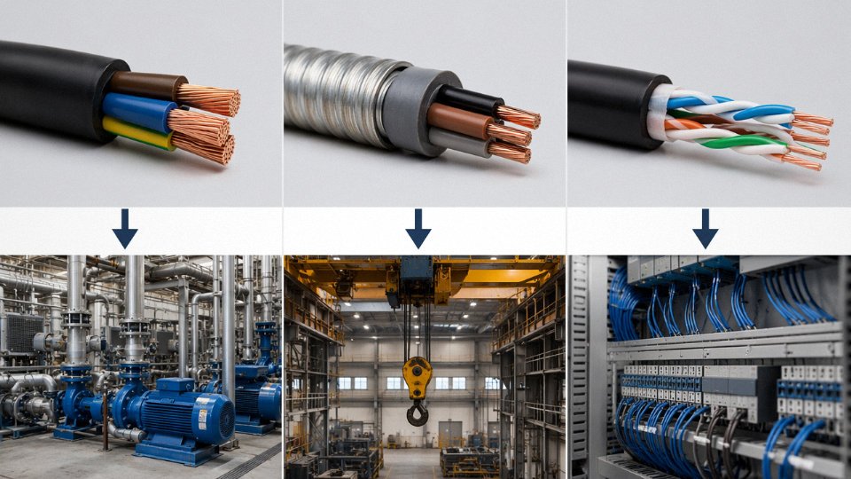
Start with one question: Is the cable carrying power above 50 V AC or its DC equivalent? If yes, you’re in power cable territory — select voltage class, then conductor material, then environment-specific construction. If no, ask a second question: Is it carrying a measurement signal or a control command? Yes brings you to instrumentation and control cable, where shielding configuration and conductor cross-section for loop resistance dominate the spec. No means you’re looking at a communication or data cable, where the governing parameters shift entirely to bandwidth, attenuation, and — for fiber — modal bandwidth versus transmission distance.
That three-question logic handles probably 90% of plant cable schedules. The remaining 10% involves hybrid cables or specialty constructions that usually get flagged by the system integrator anyway.
Common Specification Mistakes Worth Flagging
PVC-insulated LV power cable in an MV system. This one still appears, usually when a site gets upgraded from 400 V to 6.6 kV or 11 kV and the cable schedule isn’t fully reviewed. PVC insulation on a standard 600/1000 V rated cable has nowhere near the dielectric strength for medium voltage. The failure mode is insulation puncture — potentially within hours of energization, not years. Always check the voltage designation on the drum label against the system voltage, not just the nominal cross-section.
Unshielded control cables routed near VFD-driven motors. Variable-frequency drives generate high-frequency common-mode noise that couples aggressively into adjacent unshielded signal cables. In practice, a 4–20 mA flow signal running parallel to a 75 kW drive output for even a few meters can produce measurement offsets or false trips that are genuinely difficult to diagnose. The fix — individually shielded pairs with shield drain terminated at one end only — is cheap at specification time and expensive after commissioning.
Multimode fiber where single-mode is required for distance. OM3 or OM4 multimode is perfectly good up to roughly 300–500 m at 10 Gbps depending on the transceiver. Past that, modal dispersion kills the link budget. Specifying multimode for a 2 km backbone because the transceivers cost less is false economy — you’ll replace the fiber anyway, and fiber pulling labor typically costs far more than the fiber itself.
How Installation Environment Modifies the Base Selection
The cable type gets you to the right family. The installation environment determines the specific construction within that family.
Direct burial demands armored cable with an UV-resistant, crush- and moisture-resistant outer sheath — SWA or DSTA for power, armored fiber or double-sheathed for data. Cable tray in petrochemical or offshore environments requires LSZH outer sheaths with flame-retardant ratings per IEC 60332-3, because the consequences of flame propagation through a cable tray bundle in a confined space are severe. Offshore and marine installations add mud resistance, halogen-free construction, and often fire-resistant cores per IEC 60331 — the fire-resistant requirement means the cable must continue to function for a defined period (typically 90 minutes) under direct flame, which is a fundamentally different test from flame-retardant.
IEC 60331 defines fire-resistance as the cable's ability to maintain circuit integrity under fire conditions, distinct from the flame-retardant (non-propagating) requirement of IEC 60332.True
IEC 60331 specifically tests continued electrical function under fire exposure, while IEC 60332 tests only that the cable does not propagate flame — confusing the two is a common specification error in safety-critical installations.
A Realistic Multi-Type Project: Utility-Scale Solar Farm
Consider a 100 MW solar facility — not a hypothetical, just a representative project type. Three distinct cable categories appear on a single site simultaneously. Medium-voltage XLPE-insulated power cables (typically 33 kV or 35 kV rated, copper or aluminum conductor) run from the string inverter stations to the main step-up transformer. XLPE-insulated, individually shielded instrumentation cables connect weather monitoring stations, pyranometers, and ambient temperature sensors back to the SCADA system — unshielded cables here would pick up inverter switching noise and corrupt the irradiance data used for yield analysis. Single-mode fiber optic cable forms the data communication backbone from the SCADA server room to remote I/O panels across the site, covering distances of 500 m to over 2 km that would exceed the reliable reach of any copper data cable.
Same site, same project, three different cable types — each selected for entirely different reasons. That’s the practical reality of a modern electrical installation.
International Standards and Certifications That Govern Each Cable Type in Global Project Specifications
Specifying the wrong standard for a project’s jurisdiction doesn’t just create paperwork problems — it can trigger rejection at customs, void an insurance claim after a fault, or force a complete cable replacement before commissioning. For procurement managers running multi-country infrastructure programs, this is a recurring operational headache. Understanding which standards actually govern each cable type, and where they hold legal or contractual weight, is what separates a clean procurement cycle from one that unravels at the inspection stage.
Power Cable Standards by Geography
IEC 60502 is the backbone of power cable specification for most of the world outside North America. Part 1 covers cables rated up to 1 kV; Part 2 extends to 30 kV. Any project in the Middle East, Southeast Asia, or sub-Saharan Africa that references IEC will almost universally accept a cable manufactured and tested to IEC 60502-2 — which matters enormously when you’re sourcing from a single supplier for projects spread across, say, Saudi Arabia, Vietnam, and Kenya simultaneously. The UK historically used BS 6346 (PVC-insulated armored) and BS 5467 (XLPE-insulated armored), and while many UK-influenced markets have progressively aligned with IEC, you’ll still see BS references in legacy specs from Gulf Cooperation Council and East African infrastructure projects. Australia and New Zealand run on AS/NZS 5000, which diverges enough in conductor sizing conventions and sheath requirements that it genuinely needs dedicated production attention, not a relabeling exercise. North America is its own world: the NEC provides the regulatory framework, but the product certification standard is UL 44 for thermoset-insulated wire and UL 1277 for electrical power and control tray cable. A cable that passes IEC 60502 type testing does not automatically satisfy UL listing requirements — the test protocols, sample procedures, and even the way conductor resistance is measured differ enough that separate qualification is required.
Control, Instrumentation, and Fire Performance Standards
Instrumentation cables destined for oil and gas or petrochemical plants typically need to satisfy BS 5308 Part 1 (PVC insulation) or Part 2 (LSZH insulation), depending on whether the installation is in an open tray or a confined equipment room where smoke toxicity matters. Offshore and marine projects add IEC 60092 into the mix, which governs both construction and fire performance for shipboard and platform cable. For petroleum processing specifically, API RP 540 sets out electrical installation practices that influence how cables are specified, routed, and terminated — a detail that procurement teams sometimes miss until the FEED engineering review flags it.
Fire performance is its own certification hierarchy and it’s worth treating it separately. IEC 60332-1 covers flame propagation on a single cable; IEC 60332-3 tests bunched cables in a vertical tray configuration, which is the more demanding and more practically relevant test for densely cabled plant rooms. IEC 60331 addresses circuit integrity under fire — critical for emergency power and fire alarm circuits. IEC 61034 measures smoke density and matters in tunnels, airports, and transit infrastructure where evacuation visibility is a life-safety issue. Specifying only IEC 60332-1 compliance when the installation is a multi-cable tray in a petrochemical control building is a common and consequential specification error.
Data and Communication Cable Standards
Structured copper cabling for buildings references TIA-568 in North America and ISO/IEC 11801 internationally — both govern channel performance from Cat5e through Cat8, though the testing methodology and connector interface definitions differ slightly. Fiber optic cable construction falls under IEC 60794, while the fiber itself is characterized by ITU-T G.652 (standard single-mode, the workhorse of telecom and campus backbone) or ITU-T G.657 (bend-insensitive single-mode, used in FTTH and anywhere tight routing radii are unavoidable). For EU-bound projects, RoHS and REACH compliance governs what goes into the jacket and insulation compounds — specific phthalates and halogenated flame retardants that were common in cable formulations a decade ago are now restricted, and a certificate of conformance without explicit RoHS/REACH declaration will stall EU customs clearance.
How Testing and Certification Actually Works in a Procurement Workflow
Type tests are done once — or once per design variant — and cover the full construction: conductor resistance, insulation integrity, voltage withstand, bending, and fire performance as applicable. Routine tests run on every production length: conductor resistance, high-voltage spark test, insulation resistance. Factory acceptance tests (FAT) are conducted either by the manufacturer’s QC team or by a third-party inspector representing the buyer, and the resulting FAT report is what gets submitted with shipping documents for letter-of-credit compliance. For projects requiring third-party certification — BASEC in the UK, CPR (Construction Products Regulation) in Europe, or a UL listing for North America — the certificate references specific construction types, voltage ratings, and temperature ratings. Substituting a slightly different insulation compound or armor wire grade invalidates the cert, which is why responsible manufacturers maintain tight control over approved material suppliers.
Jinda produces cables to IEC, BS, AS/NZS, and SANS standards from dedicated production lines with third-party type test records, allowing a single purchase order to cover projects across the Middle East, Africa, Southeast Asia, and Oceania without separate supplier qualifications for each jurisdiction.True
Jinda operates five production bases in China with 470,000 m² of manufacturing space and serves customers in over 50 countries, supporting multi-standard production and international procurement workflows.
In practice, the ability to cover IEC, BS, and AS/NZS from one supplier qualification reduces the vendor onboarding burden on procurement teams significantly — typically the qualification process runs four to twelve weeks per supplier depending on the buyer’s internal process, so consolidating to one approved source for a multi-region program is a real schedule and cost advantage, not just a convenience.
Material Science Behind Cable Performance: Why Conductor Alloy, Insulation Compound, and Jacket Chemistry Matter
Most procurement conversations focus on voltage rating, cross-section, and price per meter. That is understandable. But the real differentiator between a cable that runs reliably for 30 years and one that degrades in five is almost never visible from the outside — it lives in the conductor purity, the insulation crosslink density, the jacket compound formulation, and whether any of that can actually be verified.
Conductor Purity: Why 100% IACS Is Not a Marketing Claim
IEC 60228 Class 1 (solid) and Class 2 (stranded) conductors are required to meet a minimum conductivity of 100% IACS — the International Annealed Copper Standard, which corresponds to a resistivity of 1.72 × 10⁻⁸ Ω·m at 20°C. ETP (electrolytic tough pitch) copper, the standard for quality cable conductors, consistently hits this mark. Cheaper alternatives — oxygen-free copper blends with trace impurities, or outright copper-clad aluminum (CCA) — do not.
CCA is the problem that keeps showing up in low-cost import quotations. The aluminum core carries roughly 61% of copper’s conductivity per unit cross-section, so a CCA conductor marked “2.5 mm²” cannot legally or safely substitute for a solid copper 2.5 mm² conductor in the same circuit. The resistance is higher, the termination behavior at lugs is different (aluminum cold-flows under compression, copper does not), and at higher operating temperatures the differential thermal expansion between the aluminum core and copper cladding causes micro-cracking at crimps over time. In practice, you will not see this failure for two or three years — by which point the cable is buried in conduit or trunked behind panels.
Copper-clad aluminum (CCA) conductors are sometimes fraudulently labeled and sold as solid copper in low-cost cable products.True
Multiple national standards bodies and industry organizations have documented CCA mislabeling. IEC 60228 requires conductors to meet specified conductivity minimums; CCA products that fail this threshold but are labeled as copper violate both the standard and basic trade law. Incoming conductor resistivity testing on rod samples is the reliable detection method.
The practical defense is simple: request incoming copper rod test certificates showing conductivity and oxygen content, and conduct spot resistivity checks on delivered drums. Jinda runs this on every rod lot before it enters the drawing process.
XLPE vs. PVC: The 20°C Difference That Actually Matters
Cross-linked polyethylene (XLPE) insulation operates at a continuous conductor temperature of 90°C; standard PVC tops out at 70°C. That 20-degree gap translates to roughly 20–30% higher ampacity for the same conductor cross-section and ambient conditions — the exact figure depends on installation method, grouping, and ambient temperature. For a large MV feeder that is borderline on a 150 mm² conductor in PVC, XLPE may remove the need to upsize to 185 mm², which is a meaningful cost difference across a long run.
Above 3 kV, PVC insulation becomes genuinely problematic. Its dielectric strength and moisture resistance are insufficient for sustained medium-voltage service. XLPE’s three-dimensional crosslinked polymer network resists moisture ingress, maintains dielectric properties at elevated temperatures, and has a significantly lower dissipation factor — all of which matter at 6 kV, 11 kV, and above. Specifying PVC insulation on a medium-voltage feeder is not just suboptimal; it is a latent failure waiting for the first hot summer combined with a high load cycle.
LSZH Jacket Chemistry: What Burning PVC Actually Does to a Substation
Standard PVC jacket compounds contain chlorine. When they burn, they release hydrogen chloride (HCl) gas. When that gas contacts fire suppression water — or simply ambient humidity — it forms hydrochloric acid. In a confined equipment room or a cable basement, this acid attacks copper busbars, relay contacts, circuit board traces, and switchgear enclosures long after the fire itself is out. The cable damage gets fixed; the corroded control panel fails six months later.
LSZH (low-smoke zero-halogen) compounds, typically polyolefin-based, limit HCl emission to below 0.5% by mass per IEC 60754-1 and maintain optical smoke transmittance above 60% in the IEC 61034-2 tunnel test. For any installation in an occupied building, a tunnel, an offshore platform, a data center, or a densely cabled control room, LSZH is not a premium upgrade — it is the specification that protects both people and adjacent equipment. The cost premium over standard PVC jacket is usually in the range of 8–18% depending on compound type and order volume, which is trivial compared to the replacement cost of a smoke-damaged switchroom.
Armor Material: Steel Works Until It Doesn’t
Galvanized steel wire armor (SWA) is the workhorse for direct burial and mechanical protection. It is cost-effective, has excellent tensile strength, and handles most industrial environments without issue. The exception is single-core AC cables at medium voltage — steel is ferromagnetic, and a single-core cable’s magnetic field induces circulating currents and eddy losses in a steel armor layer, reducing efficiency and generating heat. IEC 60502-2 addresses this directly: single-core MV cables require aluminum wire armor (AWA) specifically to avoid this ferromagnetic loss mechanism. Getting this wrong on a large single-core MV installation means elevated operating temperature, higher losses, and potentially a cable that never meets its rated ampacity in service.
For coastal installations or chemical plants where chloride or acid exposure is persistent, neither galvanized steel nor aluminum is ideal. Stainless steel wire armor — typically 316L grade — is the right call, though it adds cost and weight and needs to be specified explicitly since most standard stock runs only to SWA.
Compound Traceability: What You Should Be Able to Audit
Material science only matters if the materials are what the datasheet says they are. At Jinda’s production facilities, incoming copper rod is tested for conductivity and oxygen content before entering the wire drawing line. Insulation and jacket compound batches carry certification from the compound supplier, and batch records are retained so that any reel can be traced back to a specific production lot. Third-party compound certifications — including fire performance test reports for LSZH grades — are available for customer review during factory qualification visits or remote document audits.
For procurement teams qualifying a new cable supplier, these are the documents to ask for: incoming rod test certificates, compound batch certificates, and the third-party fire test reports that underpin any LSZH or flame-retardant claim. A supplier who cannot produce all three is either buying commodity materials without verification or has not built the traceability infrastructure that serious project specifications require.
Frequently Asked Questions About Cable Wire Types
What is the difference between a cable and a wire?
A wire is a single conductor — either solid or stranded — and may or may not carry insulation. A cable is an assembly: two or more conductors, or a single insulated conductor wrapped with additional protective layers such as a bedding, screen, armor, or outer sheath. IEC 60050 draws this distinction clearly, though in everyday commercial language — purchase orders, distributor catalogs, even engineer conversations on the floor — the words get used interchangeably. That’s usually harmless. Where it matters is specification writing: if you write “wire” on a datasheet for an armored multicore run through a cable tray, you may get exactly what you asked for and not what you needed.
Can I use a power cable for instrumentation signals?
Short answer: don’t. Power cables are designed to carry current without overheating; they are not designed to control electrical interference between conductors, and they lack the individually shielded pairs that keep a 4–20 mA analog loop clean. Running an unshielded power cable parallel to or in place of an instrumentation cable in an industrial environment will couple 50 or 60 Hz noise onto your signal. In a 4–20 mA loop — which has a 16 mA span representing your full process range — even a few milliamps of induced noise translates to a measurement error of several percent. In a flow control or pressure loop feeding a safety interlock, that error is not academic. The fix after the fact is expensive: re-pulling cable, rewiring terminations, sometimes redesigning the earthing scheme. Specify the right cable type from the start.
What does XLPE mean and why does it matter?
XLPE stands for cross-linked polyethylene. The cross-linking process — whether done by peroxide, silane, or electron-beam methods — creates chemical bonds between the polymer chains that PVC simply does not have. The practical results: the insulation retains its mechanical and dielectric properties up to 90 °C continuous (versus roughly 70 °C for standard PVC), it resists moisture penetration better, and it doesn’t soften and flow under sustained load the way PVC can at elevated temperatures. For medium-voltage cables, XLPE has largely replaced PVC as the default insulation because the cost premium over PVC is modest — typically in the range of 8–15% depending on voltage class and conductor cross-section — while the service life and thermal headroom improvements are substantial. If you are specifying an MV cable for a project expected to run 25 or 30 years, XLPE is not an upgrade; it’s the baseline.
How do I know if a cable actually meets IEC or BS standards rather than just claiming to?
A declaration on a datasheet costs nothing. What you want is third-party test evidence from an accredited laboratory — BASEC, KEMA, SGS, or equivalent — with report numbers you can verify. Check the cable drum itself: IEC 60502-compliant cables carry voltage rating, standard designation, conductor cross-section, and manufacturer identification printed directly on the sheath at regular intervals. If any of that is missing or inconsistent, that alone is a flag. Ask the supplier for a Certificate of Conformance that references specific test results, not a generic quality certificate. Any reputable manufacturer can produce actual test data on conductor resistance per IEC 60228, insulation breakdown voltage, and jacket compound properties. If they hesitate or offer a self-declaration only, treat that as a procurement risk.
Jinda cables carry third-party laboratory test documentation and drum markings consistent with IEC 60502 requirements, available for review before order confirmation.True
Established manufacturers serving export markets routinely provide accredited lab test reports and conform to IEC drum-marking requirements; this is a verifiable, standard practice for serious international supply.
What is the typical service life of an industrial cable, and what shortens it?
Well-made XLPE medium-voltage cables are designed for a service life of 30 years or more under rated conditions — that figure comes from IEC 60502 aging and thermal endurance test protocols. In practice, a handful of things erode that life faster than anything else. Sustained operation above rated ampacity is the most common: every 8–10 °C of excess temperature roughly halves insulation life by the Arrhenius relationship. Water tree degradation affects non-water-blocked XLPE in wet or buried installations; specifying a water-blocked or longitudinally sealed construction eliminates most of that risk. UV exposure matters more than people expect for above-ground runs — an unjacketed or lightly sheathed cable in direct sun in a hot climate will surface-crack within a few seasons. And mechanical damage during installation, specifically violating the minimum bending radius (typically 12–15 times the overall cable diameter for armored MV cables), creates insulation stress concentrations that may not fail immediately but will shorten service life noticeably.
Does Jinda supply custom cable designs for special project requirements?
Yes. The process is straightforward: the customer submits a technical datasheet, IFC drawing, or written specification. Jinda’s engineering team reviews it, proposes a construction — conductor cross-section, insulation system, shielding, armor type, jacket compound — and confirms compliance with the applicable standard. Sample production and third-party or in-house testing follows, and mass production begins after sample approval. For custom medium-voltage cables, lead time from approved sample to first production drum runs roughly 8–12 weeks depending on raw material sourcing and production scheduling. Highly non-standard designs involving specialty compounds or unusual voltage classes may run longer; Jinda’s team will flag that upfront rather than midway through the schedule.
What is the minimum order quantity for international procurement?
MOQ varies depending on cable type, cross-section, and whether the design is standard or custom. For standard low-voltage power cables, the floor is typically around 2,000 m per type, with full-drum quantities preferred. Specialty cables — high-flex, fire-resistant, or custom-sheathed types — generally carry a 500 m minimum. Medium-voltage cables are almost always quoted and shipped in full drum quantities, both for protection during transport and because partial drums create handling and storage problems on site. For project buyers sourcing multiple cable types, Jinda supports consolidated container shipments, which means you can combine LV power, control, and instrumentation cables in a single FCL to reduce freight cost and simplify receiving logistics. That kind of consolidation is worth discussing early in the procurement schedule, not as the container is being booked.
How Jinda’s Global Supply Infrastructure Supports Large-Scale Cable Projects Across 50+ Countries
Running a single-facility cable plant and trying to serve 50-plus countries simultaneously is the kind of operational contradiction that shows up fast — in missed lead times, in capacity conflicts between product families, and in the quiet substitutions that happen when a manufacturer runs short on a specific conductor grade. Jinda’s five-production-base structure was built specifically to avoid that problem.
Specialized Production Lines Across a 470,000 m² Footprint
The 470,000 m² total manufacturing space isn’t just a headline figure. What matters operationally is how that space is organized. Dedicated lines for low-voltage power cables, medium-voltage cables, instrumentation and control cables, and fiber optic cables run without competing for the same extrusion equipment or stranding machines. For a procurement manager placing a mixed-cable order — say, 35 kV XLPE power cable alongside multicore instrumentation cables for a substation project — this means both product families move through production simultaneously rather than queuing behind each other. Single-facility manufacturers, especially those that pivoted into product diversity without expanding infrastructure, routinely push instrumentation cable orders to the back when a large power cable contract fills their lines. That creates the kind of four-to-six-week slip that kills project schedules.
Vertical Integration and Material Traceability
Jinda draws copper rod in-house, runs its own stranding, extrusion, armoring, and sheathing operations under one quality management chain. That matters more than it sounds. When a cable manufacturer outsources conductor stranding or buys pre-fabricated insulated cores from a third party, they lose the paper trail at the point where most field failures actually originate — conductor purity, strand geometry, and insulation compound batch consistency.
Jinda's vertically integrated production — from copper rod drawing through final sheathing — means every material input is traceable to an in-house production record, not a third-party supplier's certificate.True
Vertical integration gives the manufacturer direct control and documentation of each production stage, enabling full material traceability across multi-year supply contracts — a requirement that EPC contractors and utility buyers increasingly specify in their vendor qualification audits.
For multi-year project supply schedules, this traceability is the difference between a supplier that can guarantee material consistency across delivery phases and one that quietly changes insulation compound when their sub-supplier switches batches.
Quality Systems and Testing Infrastructure
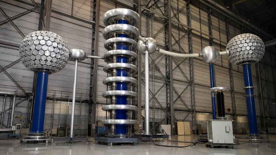
Jinda operates under ISO 9001 quality management and ISO 14001 environmental management certification. The in-house high-voltage test lab handles both type testing and routine testing for MV cables, including partial discharge testing — a capability that most mid-tier cable factories outsource to third-party labs, which adds lead time and, occasionally, introduces inconsistency in how borderline results get interpreted. For EPC contractors and utility buyers running pre-shipment inspection requirements, having that lab on-site means witness testing without coordinating external facility access.
Logistics, Lead Times, and Documentation
Export packaging goes onto steel drums — returnable or non-returnable, to IEC specification or customer-specified dimensions — and container loading is optimized for mixed-cable project orders, combining FCL and LCL configurations to avoid the cost of shipping air. Realistic transit windows from Jinda’s Shandong production bases: Middle East runs roughly 15–20 days depending on routing and port congestion; Southeast Asia is typically 7–12 days; Africa varies considerably, but 25–35 days covers most West and East African destinations; South America is generally 30–40 days, with some Pacific coast ports at the shorter end. Documentation support covers commercial invoices, packing lists, test reports, and the certificate packages required for letter-of-credit settlements — something that trips up buyers working with smaller exporters who aren’t set up for LC document discipline.
Technical Support That Extends Past the Invoice
Pre-sales engineering review — where Jinda’s technical team cross-checks a customer’s cable specification against the intended application, installation method, and local standard — catches misspecifications before they become field problems. Post-delivery support covers commissioning queries and jointing guidance. That’s not a sales pitch; it’s a practical acknowledgment that cables are installed by people who sometimes encounter edge cases the original spec didn’t anticipate.
If you’re working through a cable bill-of-materials for an upcoming project, Jinda’s international sales team — backed by 37 years of manufacturing and export experience — can turn around a technical review and competitive quotation faster than most buyers expect. Submit your specification package and let the engineering conversation start there.