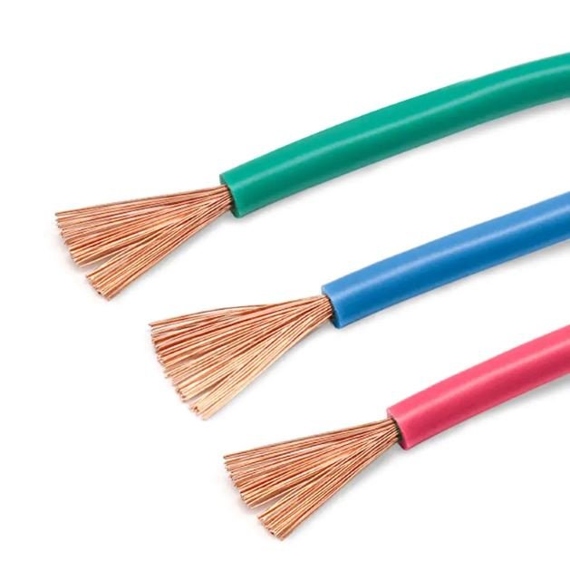
Specify the wrong cable type for a 6 kV feeder run and you’re not just looking at a re-pull — you’re looking at premature insulation breakdown, potential arc faults, and a production line down for days while the procurement cycle restarts. Choose undersized aluminum overhead conductors for a long rural span and sag becomes a clearance violation, or worse, a contact failure under summer thermal load. The mismatch between cable type and application is one of those decisions that looks cheap to get wrong until it isn’t.
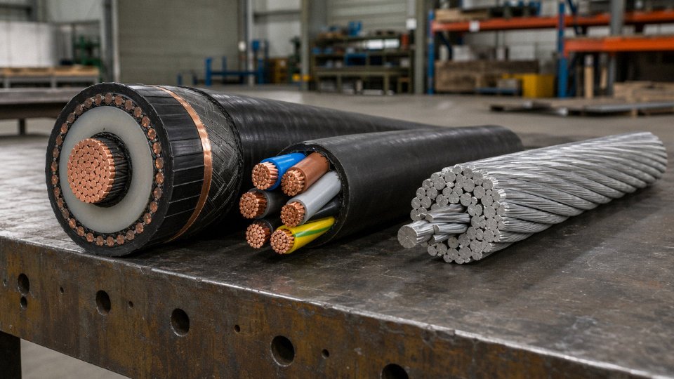
The three most common cable types used for transmitting electrical power are XLPE-insulated underground power cables, PVC-insulated low-voltage distribution cables, and overhead ACSR (Aluminum Conductor Steel Reinforced) conductors. Each serves a distinct voltage range, installation environment, and load profile — XLPE for medium- and high-voltage underground runs, PVC for low-voltage building and industrial distribution, and ACSR for open-air transmission and distribution spanning voltages from 11 kV up to 765 kV.
What makes this worth more than a quick answer is that the boundaries between these three types blur constantly in real projects — a substation contractor will often use all three within the same site, and the decision of where one ends and another begins has direct consequences for thermal rating, installation labor, and 20-year lifecycle cost. The global power cable market sat around USD 167 billion in 2023 and is tracking toward USD 290 billion by 2032, which means cable selection decisions are being made at scale, under procurement pressure, and not always by people with enough field context to get them right.
XLPE-Insulated Power Cables: The Workhorse of Modern Underground and Industrial Networks
Cross-linked polyethylene — XLPE — dominates medium- and high-voltage underground installation for a straightforward reason: the chemistry works extremely well for the application. Standard polyethylene is a thermoplastic, which means it softens and flows under sustained heat. Cross-linking fixes that. Whether the manufacturer uses peroxide cross-linking (the dominant route for MV and HV cables, involving decomposition of dicumyl peroxide at temperatures around 200–230°C during vulcanization) or silane moisture-cure cross-linking (more common in lower-voltage, smaller-conductor products), the result is a three-dimensional polymer network where carbon-carbon bonds lock the molecular chains together. The insulation no longer flows. It behaves more like a thermoset. That structural change is what delivers a continuous conductor operating temperature of 90°C and a short-circuit withstand temperature of 250°C — compared to 70°C continuous and 160°C short-circuit for standard PVC insulation. In a densely loaded urban duct route, that 20°C headroom translates directly into either higher ampacity for the same conductor cross-section or a smaller conductor for the same load, and either way you’re looking at real money saved over the life of the installation.
Construction Layer by Layer
Starting from the center: the conductor is typically stranded copper or aluminum, with compact or Milliken-segment constructions used above roughly 500–630 mm² to control overall diameter and improve flexibility. Over the conductor sits a semi-conducting conductor screen, extruded simultaneously with the insulation in a triple-extrusion process — this layer eliminates air voids at the conductor-insulation interface and smooths the electrical stress field. Then comes the XLPE insulation itself, and thickness scales with voltage class in a way that’s immediately useful to know during specification: roughly 2.5–3 mm at 0.6/1 kV, around 5.5 mm at 11 kV, climbing to approximately 18 mm at 110 kV, and approaching 27–30 mm for 220 kV designs. These aren’t arbitrary — they’re determined by working electric field stress limits, typically kept below 8–10 kV/mm for conventional XLPE to maintain long-term dielectric reliability.
Outside the insulation screen comes the metallic component, and here the engineer has real choices: copper tape for smaller distribution cables, corrugated aluminum sheath for HV cables requiring robust moisture blocking, or steel wire armoring (SWA) for mechanical protection in direct-buried or rocky-trench applications. The outer jacket is usually PVC for general underground use, LSOH (low smoke zero halogen) in tunnels or confined spaces where fire gases matter, or HDPE where chemical resistance or soil stress is a concern.
Voltage Range and Typical Applications
XLPE cables cover a practical range from 0.6/1 kV distribution cables feeding factory switchboards all the way through 66 kV, 110 kV, and 220 kV transmission circuits. At the higher end, joints and terminations become genuinely complex — a poorly made cold-shrink joint on a 110 kV cable is a latent failure waiting to happen, usually within two to five years, and the subsequent outage and excavation cost dwarfs whatever was saved by using a field team without proper factory-grade accessories and cleanliness protocols. Pre-moulded push-on joints are now standard practice for anything above 33 kV, and they demand scrupulous insulation screen penciling dimensions.
Primary application environments include urban underground distribution networks, industrial plant primary feeds, offshore wind farm inter-array cables (where the cable lays on or buried in the seabed between turbines, typically at 33 kV or 66 kV), railway traction supply cables, and data center main incomer circuits.
XLPE insulation maintains a 250°C short-circuit temperature rating, significantly higher than PVC insulation's 160°C limitTrue
The cross-linked polymer network in XLPE resists thermal deformation at temperatures that would cause PVC to soften and lose dielectric integrity, which is why IEC 60502 and IEC 60840 standards specify these respective short-circuit temperature limits for each insulation type.
XLPE Versus EPR: When the Choice Is Not Obvious
EPR (ethylene propylene rubber) occasionally comes up as an alternative, particularly for submarine cables and applications with repeated bending cycles. EPR stays flexible at temperatures down to around –50°C, whereas XLPE can become somewhat stiff and crack-prone below –20 to –30°C depending on formulation — relevant if you’re pulling cable on a cold winter morning in northern climates, or if the installation involves dynamic loading. EPR also tolerates water treeing better in some formulations. The trade-off is cost: EPR insulation typically adds 15–35% to insulation material cost depending on compound grade and conductor size, which on a large urban grid project involving hundreds of kilometers becomes a significant budget line. For most static underground installations in temperate or tropical climates, XLPE wins on economics without sacrificing performance.
Installation Constraints Engineers Often Underestimate
Minimum bending radius for armored MV XLPE cables runs typically 15 times the overall cable diameter — for a three-core 95 mm² 11 kV SWA cable with an overall diameter around 55–65 mm, that means you need roughly 825–975 mm clearance in any bend, which catches project teams off guard when routing through congested cable cellars. Pulling tension limits depend on conductor cross-section and pulling method, but a general field rule is to stay below 50 N/mm² on the conductor cross-sectional area for horizontal pulls, lower if the duct has multiple bends. Ignore these limits and you risk stretching or displacing the conductor screen — invisible damage that only reveals itself as partial discharge years later.
Benchmark Reference Table
| Parameter | Typical Value / Range |
|---|---|
| Conductor size range | 16 mm² to 2,500 mm² |
| Current-carrying capacity, 95 mm² Cu, single-core, direct buried, 20°C ambient | 220–270 A (depends on soil thermal resistivity and burial depth) |
| Three-core 95 mm² 11 kV SWA XLPE cable weight | roughly 4.5–5.5 kg/m (varies with armor wire diameter and jacket thickness) |
| Insulation thickness at 11 kV | ~5.5 mm nominal |
| Insulation thickness at 110 kV | ~18 mm nominal |
| Short-circuit temperature limit | 250°C |
| Continuous operating temperature | 90°C |
PVC-Insulated Power Cables: Cost-Effective Reliability for Low-Voltage Distribution and Building Wiring
PVC cable doesn’t get much glory in engineering discussions — everyone wants to talk about XLPE or exotic fire-resistant compounds — but walk through any commercial building, residential complex, or light industrial facility and the overwhelming majority of what’s in the walls and cable trays is PVC-insulated. There’s a reason for that. It works, it’s cheap, and when it’s specified correctly and sourced from a reputable manufacturer, it lasts decades without issues.
What’s Actually Inside the Compound
The performance of any PVC cable lives or dies in the formulation of the insulation compound, and this is where procurement managers often get burned by cutting corners on price.
Standard PVC insulation is not a single material. It’s a blend: base PVC resin, plasticizers (typically phthalate or adipate esters) to control flexibility, heat stabilizers (lead-based in older formulations, calcium-zinc systems in most modern cable to meet RoHS constraints), and flame-retardant additives, often antimony trioxide combined with a halogenated synergist. The ratio of these components determines whether you get a cable rated for 70°C continuous conductor temperature, a heat-resistant grade pushing 90°C, or a cold-weather flexible grade that stays pliable down to around -30°C or even -40°C in Arctic-specification products.
This matters operationally. A standard 70°C PVC cable installed in a cable tray with poor airflow, running at higher-than-anticipated loads, can hit its temperature ceiling faster than the designer assumed — particularly in summer. The heat-resistant PVC grade costs maybe 8–15% more at the compound level but gives meaningful headroom in those situations.
Construction and Standards
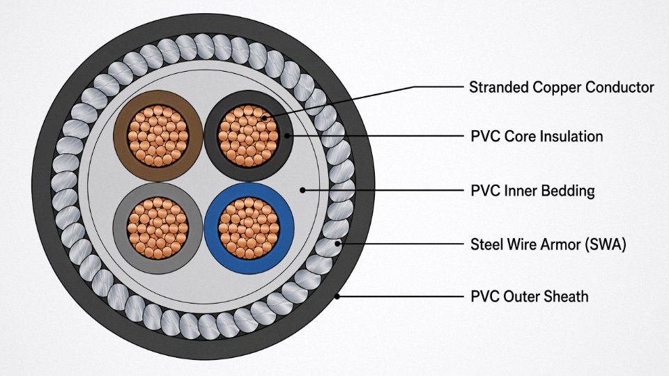
A typical low-voltage PVC power cable per IEC 60502-1 (0.6/1 kV rated) runs from the inside out: plain or stranded copper conductor (or aluminum for larger sizes above roughly 16 mm²), PVC insulation on each core, a PVC inner bedding layer, optional steel wire armor (SWA) or steel tape armor (STA) for mechanical protection, and a PVC outer sheath. IEC 60227 governs the lighter building wire and flexible cord versions that show up in fixed wiring and appliance drops.
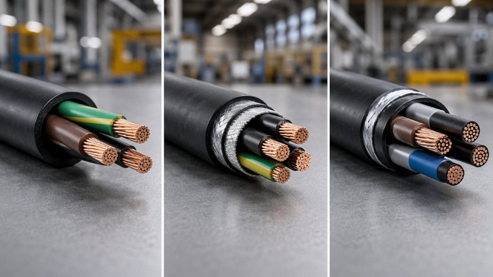
The armor decision is where project engineers sometimes overthink it. For direct burial in controlled soil conditions with stable pH and no significant mechanical risk, unarmored with adequate burial depth is often fine. Add SWA where you have rocky backfill, vehicle crossings, or any realistic chance of excavation activity nearby.
The Limitations You Have to Manage
PVC’s temperature ceiling of 70°C continuous (160°C short-circuit maximum, compared to XLPE’s 250°C) restricts how much current you can push through a given conductor cross-section. For most low-voltage distribution and building wiring, this is a non-issue — the ampacity tables in IEC 60364 or local electrical codes already account for it.
The serious limitation is fire behavior. When PVC burns, it releases hydrogen chloride gas and generates dense, black, highly opaque smoke. HCl is corrosive to electronics and toxic in enclosed spaces, which is why PVC cable is explicitly prohibited or severely restricted in underground transit tunnels, hospitals, airports, schools, and other public occupancy buildings in jurisdictions following IEC 60332 or EN 50525.
PVC cables release hydrogen chloride (HCl) and dense black smoke when burned, making them unsuitable for tunnels, hospitals, and other public buildings under IEC 60332 and EN 50525 requirements.True
HCl emission during combustion is a well-documented property of halogenated PVC compounds; IEC 60332 series and EN 50525 specifically address fire performance requirements that lead specifiers toward LSOH alternatives in high-occupancy or enclosed environments.
In those applications, you need LSOH (Low Smoke Zero Halogen) cable. That’s a different product family, not a PVC variant.
Voltage Range and Where PVC Stays Competitive
PVC insulation is technically viable up to 6/10 kV in medium-voltage designs, and you’ll see it specified there occasionally in cost-sensitive markets. In practice, above 1 kV the advantages evaporate. XLPE handles higher operating temperature, carries more current for the same conductor size, and performs better under partial discharge stress. That’s why XLPE effectively took over medium-voltage applications from around 3.6/6 kV upward during the 1990s and 2000s.
PVC’s economic case is sharpest at 0.6/1 kV. PVC compound typically costs 30–50% less per kilogram than XLPE compound — the exact gap depends on crude oil derivative pricing, plasticizer market conditions, and order volume — which translates to roughly 15–25% lower finished cable cost for equivalent low-voltage conductor sizes. On a large residential development or commercial fit-out with tens of kilometers of 4–95 mm² wiring, that difference is real money.
Where PVC Makes Sense
Residential and commercial building wiring is the obvious home. Light industrial machinery wiring, control panel interconnects, agricultural installations in stable soil, temporary power distribution on construction sites — these are all appropriate applications. The combination of adequate mechanical toughness, reasonable flexibility in the standard grade, straightforward termination, and low cost makes it the sensible default where fire performance requirements don’t dictate otherwise.
A Procurement Warning Worth Heeding
Substandard PVC cable is one of the more common quality problems in the market, and it’s not always obvious at incoming inspection. Under-plasticized insulation that passes a basic dimensional check will start cracking within a few years of installation, especially in installations with any UV exposure or thermal cycling. Specify IEC 60811 testing for physical and mechanical properties — tensile strength, elongation at break, and ageing tests — or ASTM D2219 if you’re sourcing for a North American project, and require third-party test reports. It’s a small addition to the purchase order that eliminates a large class of field failure risk.
Overhead Bare and Covered Conductor Cables: Spanning Continents at High Voltage and Low Cost Per Kilometer
Overhead conductors are the reason bulk electricity transmission is economically viable at all. Strip away the engineering and the numbers tell the story bluntly: a single-circuit 230 kV ACSR line across flat terrain typically runs USD 150,000–400,000 per circuit-kilometer depending on tower type, conductor size, ground conditions, and labor market. The equivalent underground XLPE cable circuit at the same voltage lands somewhere between USD 1 million and USD 4 million per circuit-kilometer once you factor in trenching, cable joints every 500–800 m, and the civil work that eats most of the budget. For a 200 km rural transmission corridor, that cost gap is simply not closable by any insulation breakthrough or installation efficiency gain in the foreseeable future.
The Four Principal Overhead Conductor Families
AAC (All Aluminum Conductor) uses concentric layers of 1350-H19 aluminum with no steel reinforcement. Low weight and good conductivity, but the sag under its own weight limits practical spans to roughly 100–200 m. You see it in dense urban distribution where towers or poles are close together and corrosion from industrial atmosphere is the bigger concern than mechanical tension.
ACSR (Aluminum Conductor Steel Reinforced) is the global workhorse. A galvanized or aluminum-clad steel core — one wire or a stranded bundle — runs through the center, with concentric aluminum layers wrapped around it. The steel carries tension; the aluminum carries current. That division of labor lets ACSR span 400 m or more between towers and handle transmission voltages from 11 kV up to 765 kV. Strand configurations matter enormously here. A 6/1 (6 aluminum strands over 1 steel wire) gives a high steel-to-aluminum ratio, useful where mechanical strength per unit weight is paramount — mountain crossings, river spans. A 26/7 or 54/7 configuration pushes the aluminum fraction up, improving conductivity at the cost of some tensile strength. The standard Drake ACSR (795 kcmil, 26/7) has a rated breaking strength of roughly 140 kN, a DC resistance of about 0.0390 Ω/km at 20°C, and a standard maximum operating temperature of 75°C. Those numbers get cited constantly in transmission planning, and they’re a reasonable baseline for most temperate-climate projects.
AAAC (All Aluminum Alloy Conductor) uses 6201-T81 aluminum alloy throughout. No steel means no galvanic corrosion at the steel-aluminum interface — a real problem in coastal or marine environments where salt spray accelerates corrosion inside the strand bundle even when the outer surface looks fine. AAAC costs a bit more per ton than ACSR but can outlast it by decades in aggressive coastal sites. Utilities in tropical island networks and coastal industrial zones have largely shifted to AAAC for this reason.
Covered overhead conductors (CC) add a thin XLPE or HDPE jacket — typically 2–4 mm — over the aluminum conductor. They are not fully insulated in the underground cable sense; contact with a grounded object still causes a fault. But that covering dramatically reduces the fault rate on distribution lines passing through forested areas, high-wind zones, or locations where branches and debris contact conductors regularly. Scandinavia, Japan, and much of Southeast Asia have deployed covered conductors extensively. The reduction in fault frequency compared to bare conductors runs up to 70% in dense forest applications, which translates directly into fewer crew deployments, less wildlife and tree-contact outage time, and lower fuse and recloser replacement costs. Cost per kilometer sits well below underground cable while delivering most of the reliability benefit for distribution voltages.
Sag, Tension, and the Physics You Cannot Ignore
Sag calculation is where overhead line engineering gets genuinely unforgiving. Every degree Celsius of conductor temperature rise produces measurable additional sag — the exact amount depends on conductor type, span length, and initial stringing tension, but ignoring it leads to clearance violations under peak summer load. Add ice loading per IEC 60826 or NESC (depending on your jurisdiction) and the design sag at maximum temperature plus maximum ice can be startlingly larger than the everyday sag engineers observe at commissioning.
Creep elongation compounds this over time. Aluminum strands under sustained tension slowly elongate over years and decades of service, permanently increasing sag beyond the elastic component. Conductors are typically pre-tensioned or the design sag is set conservatively to account for 10–30 years of creep — the range depends on initial tension as a fraction of rated breaking strength and average operating temperature.
ACSR overhead transmission lines typically cost 5–20 times less per circuit-kilometer than equivalent-voltage underground XLPE cable installations.True
Published utility cost studies and engineering estimates consistently place overhead ACSR transmission at USD 150,000–400,000/circuit-km and underground XLPE at USD 1–4 million/circuit-km at comparable voltages, a ratio of roughly 3x to over 20x depending on terrain, cable voltage, and regional labor costs.
HTLS Conductors for Reconductoring Without New Towers
When a utility needs more ampacity on an existing corridor — and building new towers is off the table for permitting, cost, or right-of-way reasons — HTLS (high-temperature low-sag) conductors are often the answer. ACCC (Aluminum Conductor Composite Core) replaces the steel core with a carbon-fiber composite, cutting core weight roughly in half and allowing operating temperatures up to around 180–200°C without the sag that would violate clearances. TACSR (Thermal-Resistant Aluminum Alloy Conductor Steel Reinforced) uses a modified aluminum alloy that resists annealing at temperatures up to 150°C or higher in advanced variants. Both products can roughly double the thermal rating of a corridor compared to standard ACSR on the same towers, though the installed hardware — dead-end fittings, suspension clamps, tension insulators — must all be reviewed and often upgraded. The conductor itself is the more tractable part of the reconductoring budget; the hardware and line work usually dominate actual project cost.
Head-to-Head Specification Comparison: Selecting the Right Cable Type for Eight Common Project Scenarios
No cable type wins universally. The right answer depends on voltage, burial depth, fault-current duration, whether the route is urban or rural, and — increasingly — fire performance codes that procurement teams sometimes don’t see until a building inspector flags them at commissioning. The table below cuts through that complexity.
| Scenario | Recommended Type | Voltage Level | Conductor | Insulation | Armor/Sheath | Reference Standard | Key Selection Driver |
|---|---|---|---|---|---|---|---|
| Urban underground feeder | XLPE MV cable | 11–33 kV | Copper | XLPE | SWA + LSOH outer | IEC 60502-2 | Space constraint favors compact copper; SWA for rocky urban trenches |
| Rural overhead distribution | ACSR or AAAC bare conductor | 11–132 kV | Aluminum | None (bare) or PE covered | N/A | IEC 61089 / ASTM B232 | Weight and cost per km dominate; aluminum wins decisively |
| Industrial plant internal power | XLPE or PVC LV/MV cable | 0.6/1 kV–6.6 kV | Copper | XLPE preferred; PVC acceptable ≤1 kV | SWA or unarmored in cable tray | IEC 60502-1 | Flexibility, fault-current rating, tray fill density |
| Offshore wind inter-array | XLPE submarine cable | 33–66 kV | Copper | XLPE | Lead sheath + AWA + polyethylene | IEC 60502-2 / CIGRE TB 623 | Seawater ingress; AWA avoids eddy current in single-core configuration |
| Railway traction supply | XLPE single-core HV | 25 kV (AC) or 1.5/3 kV (DC) | Copper | XLPE | AWA or SWA depending on routing | EN 50264 / IEC 60502 | High fault-current cycling; EMC shielding requirements |
| Hospital or airport critical power | XLPE or mineral-insulated, LSOH | 0.6/1 kV | Copper | XLPE + LSOH jacket | Unarmored or SWA in conduit | IEC 60331 / EN 50200 | Circuit integrity under fire — 30–120 min survival mandatory |
| Residential apartment building | PVC or LSOH-insulated LV | 0.6/1 kV | Copper | PVC or XLPE with LSOH | Unarmored in conduit | IEC 60332-3 / local building code | Flame retardancy category, cost, code compliance |
| Long-distance bulk transmission | ACSR or ZTACIR overhead | 220–765 kV | Aluminum + steel core | Bare | N/A | IEC 61089 / ASTM B711 | Thermal rating, sag control over long spans — sometimes 400 m+ |
The Copper-Versus-Aluminum Decision in Practice
Aluminum has roughly 61% the conductivity of copper, which means you need approximately 1.6× the cross-section to achieve equivalent resistance — 240 mm² aluminum for what 150 mm² copper would handle, roughly speaking.
Aluminum conductors weigh approximately 30% as much as copper conductors of equivalent length and carry 40–60% lower material cost depending on market conditions.True
These figures reflect the difference in density (aluminum ~2.7 g/cm³ vs. copper ~8.9 g/cm³) and long-run commodity pricing. The cost range varies with copper/aluminum LME spread at time of purchase.
Overhead lines almost always go aluminum. A heavier copper conductor would demand shorter span distances, heavier towers, and deeper foundations — the civil cost alone swings the economics badly against copper. Underground is different. In congested urban ducts where you’re paying by the millimeter of duct space or fighting conduit fill limits, the larger aluminum cross-section can force you to upsize conduit or reduce circuits per trench. Copper wins that argument in tight urban infrastructure. In industrial plants with generous cable trays, aluminum LV cables have made a quiet comeback over the last decade, mainly on feeders above 95 mm² where the cost saving is substantial enough to justify the larger lug sizes and the slightly more careful installation practice at joints.
Armoring: Match the Threat, Not the Habit
Steel wire armor handles direct burial in rocky ground, areas with rodent pressure, or cables subject to vehicular loading. Steel tape armor suits cables pulled through smooth conduit where the tape adds crush resistance without the mechanical overkill of SWA. Single-core cables above roughly 70 mm² should use aluminum wire armor rather than steel — steel generates eddy current losses in single-core AC configurations that can reach 10–15% of resistive losses, which over a 30-year asset life is a significant number. Unarmored cables belong in protected environments: cable trays, enclosed conduit, equipment cubicles.
Fire Performance Is Not Optional for Public Infrastructure
IEC 60332-1 and -3 cover flame propagation in single and bundled cables. IEC 60331 and EN 50200 address circuit integrity — meaning the cable must keep conducting during a fire, not merely not burn. For hospitals, airports, tunnels, and underground transit, most national building codes adopted after roughly 2010 mandate LSOH (Low Smoke Zero Halogen) jacket compounds. PVC, when it burns, releases hydrogen chloride gas that damages electronics, corrodes metal structures, and incapacitates occupants before flame contact. In a confined public space, that matters more than the 15–20% jacket cost premium for LSOH.
Decision Flowchart Logic
Start with voltage level: above 1 kV eliminates PVC immediately and points to XLPE or bare overhead conductors. Then ask whether the route is overhead, underground, or indoor — overhead resolves to ACSR/AAC/AAAC; underground and indoor continue to the next branch. From there, check fire performance requirements: if IEC 60331 circuit integrity or IEC 60332-3 Category C/D flame retardancy is specified, the jacket compound is locked to LSOH or mineral insulation, which narrows manufacturer options significantly. Then determine conductor material using the space-versus-cost logic above. That sequence — voltage → environment → fire class → conductor material — lands you at a cable family in four decisions, and it filters out the expensive mismatches before anyone cuts a purchase order.
International Standards, Testing Protocols, and Certification Marks Engineers Must Verify Before Procurement
Buying cable on price alone — without verifying the standard it was built to — is one of the faster ways to commission a system that fails within three years. The fraud is rarely obvious. The drum looks right, the print on the jacket reads all the correct numbers, and the paperwork looks complete. What you cannot see without testing: conductor cross-section that’s 6% light, XLPE that was never properly cross-linked, aluminum rod made from mixed or recycled scrap. Each of those defects is invisible at delivery and catastrophic in service.
Matching Cable Type to Its Governing Standard
Start with the standard map before you write a purchase order. For underground XLPE and PVC cables rated 1 kV through 30 kV, IEC 60502 is the primary reference — Part 1 covers up to 3 kV, Part 2 covers 6 kV through 30 kV. Conductor construction for all cable types falls under IEC 60228, which defines Class 1 (solid), Class 2 (stranded), Class 5 and 6 (flexible) tolerances including the ±1% DC resistance limit that exposes under-area conductors. Current-carrying capacity calculations follow IEC 60287; if a manufacturer quotes ampacity figures without referencing soil thermal resistivity, installation depth, and grouping factors, those numbers are guesses.
For overhead conductors, IEC 61089 governs ACSR and AAC construction in most international markets; ASTM B232 is the North American equivalent for ACSR specifically and remains widely referenced in Middle Eastern and African projects even outside the US. High-voltage cables above 30 kV step up to IEC 60840 (30 kV–150 kV) and IEC 62067 for 150 kV and above — these standards impose substantially heavier type-test regimes that few manufacturers can actually pass without dedicated HV test infrastructure.
What the IEC 60502-2 Type Tests Actually Reveal
For medium-voltage XLPE cables, the mandatory type test suite under IEC 60502-2 is where quality either holds up or doesn’t. Partial discharge measurement at 2U₀ must show less than 10 pC — a higher reading points directly to voids, contaminants, or micro-cracks in the insulation that will eventually tree and fail. The tan delta test at elevated temperature (typically 2U₀, conductor at 90°C) catches insulation compound substitution; a supplier who blended cheap filler into the XLPE compound will show elevated dielectric loss that a cold-temperature test might miss entirely.
The hot-set elongation test is the one I’d never waive. A sample of the XLPE insulation is loaded under mechanical stress at 200°C — if the cross-linking network is inadequate, the material flows rather than recovers. Failure here means the cable will deform thermally under fault current conditions, exactly when you need it to hold geometry. Bending tests and insulation resistance measurements round out the suite, but hot-set is the fingerprint of genuine cross-linking versus a cable that was merely heat-treated and relabeled.
Third-Party Certification Marks Worth Trusting
Not all certification marks carry equal weight in practice. KEMA (now KEMA-DEKRA) and CESI type test reports are generally the most rigorous for MV and HV cables — a full KEMA type test for a 33 kV XLPE cable runs to expensive hours of testing and is genuinely difficult to falsify. UL listing is non-negotiable for North American projects; CE marking matters for European supply, though it is a declaration of conformity rather than third-party tested in most cable categories. CCC (China Compulsory Certification) is mandatory for cables sold into the Chinese domestic market. For Gulf Cooperation Council projects, SASO certification has become a real procurement gate — Saudi Aramco and similar clients will reject shipments without it.
IEC 60228 Class 2 conductor tolerance allows a maximum of -1% deviation from nominal DC resistance, meaning a conductor measuring more than 1% above the specified resistance value at 20°C fails the standard.True
IEC 60228:2004 Table 1 specifies maximum DC resistance values at 20°C for each conductor cross-section and class. A conductor supplied below nominal cross-sectional area will exhibit higher resistance; the standard's resistance limit is the enforceable boundary, not a nominal area tolerance. Manufacturers supplying conductors 5–8% below nominal area typically violate this resistance limit.
Fraud Vectors That Show Up More Often Than They Should
Falsified test reports are the most common issue — in practice, a PDF with plausible numbers is easy to produce, and many procurement teams never request the actual test laboratory to verify. Ask for the report reference number and contact the issuing lab directly. Some will confirm; others won’t respond, which is itself an answer.
Conductor under-tolerance is endemic in certain price-competitive markets. A conductor nominally rated 95 mm² supplied at 88–90 mm² actual area will run hotter, lose more voltage, and eventually fail insulation prematurely — all while appearing compliant on paper. The fix is simple: incoming resistance measurement per IEC 60228 on a sample from each drum before installation. It takes about 20 minutes per sample.
Contaminated aluminum in overhead conductors is a different problem. Recycled aluminum with inconsistent alloy composition reduces tensile strength unpredictably — ACSR and AAAC depend on mechanical properties as much as conductivity, and a span designed for standard breaking strength that uses off-spec wire will creep excessively and potentially fail under ice load or wind.
The Factory Audit Checklist for International Buyers
Before committing to a significant overseas cable procurement, a plant audit is worth the travel cost. The short checklist that actually filters quality: verify conductor resistance testing per IEC 60228 is performed on every production batch, not spot-checked; confirm the hot-set test is run in-house with calibrated equipment; walk the extrusion lines and check whether spark testing is continuous on MV cable insulation (gaps in spark test coverage mean untested defects are shipping); measure insulation eccentricity on cut samples — wall variation above roughly 10–15% indicates extrusion process instability; and verify final drum lengths against a laser or optical measurement system rather than relying on a counter wheel, which slips and drifts.
Jinda’s five production bases each operate dedicated testing laboratories, and the group holds ISO 9001 certification covering the full production and delivery cycle. The export certification portfolio spans more than 50 destination countries, which means the documentation infrastructure for KEMA reports, SASO, UL, and regional equivalents is not assembled project by project but maintained as standing capability. That is the practical benchmark: a qualified supplier should not be scrambling to locate their test reports when you ask.
Total Cost of Ownership Across a 40-Year Cable Asset Life: What the Purchase Price Alone Never Tells You
Purchase price is the number procurement gets asked about first. It is almost never the number that matters most.
A cable asset installed today will sit in the ground, overhead, or inside a duct bank for four decades. The capital you spend on day one — conductor material, insulation grade, armoring — is typically 15–30% of what that cable actually costs your operation over its full life, depending on load factor, local energy rates, and how often you have to dig it up. Finance departments almost always look at the unit price per meter. Engineers who have dealt with an early-replacement project know exactly how expensive that blind spot is.
Building a Realistic TCO Model
The full lifecycle cost of a power cable breaks into six buckets: initial material cost, installation labor and civil works, jointing and termination hardware, capitalized energy losses over service life, maintenance and inspection, and end-of-life scrap recovery (net of disposal). Most procurement analyses stop at bucket one. Some include installation. Very few model energy losses seriously, which is where the real money usually hides.
Jointing hardware alone deserves attention. A single 11 kV straight joint for an XLPE three-core cable runs roughly USD 400–900 per joint depending on voltage class and manufacturer; heat-shrink versus cold-applied systems differ in both material cost and installation time. If your cable design requires a joint every 500 m, that adds up fast on a multi-kilometer run, and each joint is a future failure point.
Conductor Size and the Economics of Resistive Losses
Ohmic losses are where conductor sizing decisions pay off — or don’t — over decades.
A 95 mm² aluminum conductor carrying 200 A continuously dissipates roughly 12 W per meter as resistive heat. Stepping up to 150 mm² aluminum drops that to around 8 W/m — a reduction of about 4 W/m. Run 100 meters of cable at that load, continuously, at USD 0.10/kWh (a conservative industrial tariff; many regions are already above this), and over 40 years the energy saving on that single 100 m segment exceeds USD 17,000. The larger conductor costs more upfront — typically 35–50% more on conductor material alone for that size jump — but in most continuous-load industrial applications the payback lands somewhere between 5 and 7 years. After that, you are simply capturing savings.
Upgrading from 95 mm² to 150 mm² aluminum conductor on a 200 A continuous load saves approximately 4 W/m in resistive lossesTrue
Resistive loss per unit length scales with current squared divided by conductance; 95 mm² aluminum at 200 A produces roughly 12 W/m and 150 mm² produces roughly 8 W/m under the same current, consistent with standard aluminum conductivity of approximately 35 m/Ω·mm²
The effect compounds if energy costs rise — and historically, over 40-year horizons, they do.
XLPE Versus PVC: The Hidden Replacement Cost
XLPE cable designed to IEC 60502-1 carries a thermal design life of 40 years at its rated continuous conductor temperature of 90°C. Standard PVC insulation, rated to 70°C continuous, begins to plasticize, stiffen, and crack noticeably in outdoor or elevated-temperature environments within 20–25 years — sometimes sooner if the cable has been thermally cycled hard. Replacing a buried three-core 11 kV cable mid-life means excavation, traffic management if it’s under a road, new jointing, and an outage window. In urban installations those civil costs routinely run USD 80–200 per linear meter or more. That’s before you account for lost production during the outage.
The TCO table below illustrates what this looks like on a realistic 1 km, 11 kV, three-core, 95 mm² cable run at 200 A and 70% load factor.
| Cost Element | PVC-Insulated (20-yr horizon) | PVC-Insulated (40-yr horizon*) | XLPE-Insulated (20-yr horizon) | XLPE-Insulated (40-yr horizon) |
|---|---|---|---|---|
| Initial cable material | Lower baseline | Lower + replacement cost | ~10–18% premium over PVC | Same cable, no replacement |
| Civil installation (1 km) | USD 80–150 k | Paid twice | USD 80–150 k | Paid once |
| Jointing hardware | USD 4–9 k | Paid twice | USD 5–10 k | Paid once |
| Capitalized energy losses (USD 0.10/kWh) | ~USD 85–95 k | ~USD 170–190 k | ~USD 75–85 k† | ~USD 150–170 k† |
| Maintenance and inspection | Moderate | High (aging insulation) | Low to moderate | Low to moderate |
| Scrap recovery credit | Low (PVC jacketed Al) | Low | Moderate (Al or Cu) | Moderate (Al or Cu) |
*PVC 40-year horizon assumes one full replacement at year 22–25, including civil works and outage costs. †XLPE cables can typically carry slightly higher load at same conductor temperature, marginally improving loss economics.
The XLPE premium generally recovers within 8–12 years through the combination of lower losses and the avoided mid-life replacement. By year 40, the gap is substantial.
Overhead Conductor Reconductoring: A Different Kind of TCO Calculation
For transmission engineers evaluating congested urban feeders, the reconductoring question surfaces regularly. Replacing standard ACSR with a High-Temperature Low-Sag (HTLS) conductor — ACCC is the most common type in practice — on an existing 132 kV line can roughly double circuit ampacity without touching the towers or ROW. Cost is in the range of 25–35% of what a parallel line would require. On a congested urban feeder where ROW acquisition alone might take a decade and tens of millions of dollars, payback periods of 5–10 years are realistic. It’s not always the right answer — conductor sag calculations and tower hardware compatibility need careful checking — but it often beats waiting years for new infrastructure.
Scrap Recovery: Net It Against Your Capital Cost
Copper conductors retain roughly 85–90% of their material value at end of life; aluminum comes in at around 70–75%, depending on alloy grade and market conditions at time of recovery. On a large project these numbers are real money. A 1 km run of 95 mm² three-core copper cable contains somewhere between 850 and 900 kg of copper; at end-of-life scrap prices that’s a meaningful credit that belongs in your 40-year NPV comparison. If you are choosing between aluminum and copper purely on capital cost without netting the scrap recovery differential, you are making the comparison on incomplete data.
The honest takeaway: cable decisions made purely on purchase price per meter will almost certainly cost more over a 40-year asset life than decisions made on full lifecycle economics. The engineer’s job is to build that model and make the case clearly — because finance will default to the cheaper line item unless shown otherwise.
Frequently Asked Questions About Power Transmission Cable Types
What is the difference between power cable and control cable?
The short answer: one moves energy, the other moves information. Power cables carry load current to motors, lighting, drives, and process equipment — conductor cross-sections typically run from 1.5 mm² up to 2500 mm² depending on the application, and insulation is rated for the full system voltage. Control cables, by contrast, carry low-level signals for switching, monitoring, and instrumentation loops. Their conductors are almost always in the 0.5–6 mm² range, and their insulation voltage rating is usually 300/500 V or 600/1000 V at most.
Construction standards differ too. Control cables under IEC 60227 or BS 3573 prioritize flexibility, multi-core count (you’ll often see 12, 19, or 37 cores in a single jacket), and signal integrity — shielding is common. Running the two cable families in the same conduit or tray is a mistake you’ll regret: power cables induce noise into unshielded control conductors, and you’ll end up chasing ghost faults in your PLC for months.
Can XLPE cables be used outdoors without a conduit?
Yes, but jacket material matters more than most spec sheets make obvious. A UV-stabilized HDPE outer sheath or a carbon-black-pigmented UV-resistant PVC jacket handles direct sunlight reasonably well over a 25–40 year service life. Standard natural or lightly pigmented PVC will degrade noticeably within 3–5 years of continuous sun exposure — it chalks, cracks, and eventually loses mechanical protection entirely. If you’re running cable across an open rooftop in a high-UV-index climate (Southeast Asia, the Middle East, northern Australia), specify the jacket explicitly in your purchase order and ask for the UV resistance test data. Don’t assume black means compliant.
Why do some overhead cables have a grease-filled steel core?
Galvanized steel strands corrode from the inside out in coastal and tropical environments. Moisture works into the interstices between strands, chloride ions attack the zinc coating, and within 15–25 years you can have a structurally compromised core while the aluminum looks perfectly fine from the outside. Flooding those interstices with zinc-chromate grease per ASTM A475 blocks moisture ingress effectively. In marine or high-humidity climates, greased-core ACSR can realistically add 15–20 years to service life — that’s a meaningful lifecycle cost argument when tower replacement means a helicopter crew and two weeks of outage coordination.
What conductor cross-section should I use for a 100 kW three-phase motor at 400 V over a 50-meter run?
Full-load current on that motor is roughly 144 A (assuming ~0.87 power factor and 93% efficiency — both vary, so confirm your motor nameplate). A 50 mm² copper XLPE cable in conduit is typically adequate against IEC 60364-5-52 derating tables under standard installation conditions. That said, you still need to check voltage drop independently. Motor feeders should stay under 3% voltage drop at full load, and 50 meters at 144 A through 50 mm² copper usually lands right at that limit — sometimes just over if the conduit is crowded. Short-circuit withstand is the third check. Run all three before you order.
How do I verify that an XLPE cable meets IEC 60502 without sending it to a laboratory?
You can’t replicate a full type test on a loading dock, but you can do meaningful screening. Request the manufacturer’s type test report from an accredited third-party laboratory — KEMA, CESI, and SGS are well-recognized; a report from an in-house lab with no external accreditation should raise immediate questions.
An insulation resistance test at 2.5 kV DC is a reliable field indicator of XLPE cable insulation quality at point of delivery.True
While it does not replace laboratory type testing, IR testing per IEC 60502 acceptance criteria — values below 100 MΩ·km indicate insulation degradation or moisture ingress and justify rejection or further investigation before installation.
Cross-check drum lengths physically. Laser measurement on delivery against the drum label catches short-shipped drums, which is more common than it should be on competitive price tenders. Simple insulation resistance testing at 2.5 kV DC, with values below 100 MΩ·km flagging insulation degradation or moisture ingress, rounds out a reasonable receiving inspection. It won’t catch a poor compound formulation, but it catches most handling and storage damage.
What is the maximum voltage for PVC-insulated cable, and why?
Practically, 6/10 kV is the ceiling for PVC power cable. The physics behind that limit is partial discharge. In PVC insulation, the partial discharge inception voltage converges uncomfortably close to operating voltage at medium-voltage levels — sustained partial discharge creates electrical treeing through the insulation matrix, and eventually the cable fails. XLPE and EPR insulation have much higher PD inception levels and far better resistance to treeing, which is exactly why every medium-voltage network above roughly 6 kV defaults to them. Specifying PVC at 11 kV or above is not a cost optimization; it’s a failure mode you’re scheduling in advance.
How does Jinda support international buyers with large-volume cable procurement?
Jinda’s involvement starts at specification review, not at shipment. Technical engineers work through conductor sizing, insulation grade selection, and standard compliance (IEC, BS, ASTM, local grid codes) before a purchase order is placed — which matters when a project spec has ambiguities that could otherwise result in a rejected delivery 14 weeks later. Factory inspection coordination, custom drum lengths and reel configurations for project-specific logistics, and multimodal export from five production bases across China give buyers meaningful flexibility on lead time and container consolidation. Full documentation packages — IEC type test reports from accredited laboratories, raw material certifications, and country-specific compliance declarations — ship with every order. For buyers managing long-term supply programs across multiple project sites, that paperwork discipline is usually worth more than the per-meter price difference.
How to Write a Cable Purchase Specification That Protects Your Project from Costly Substitutions
A purchase order that says “11 kV XLPE cable, 95 mm², three-core, aluminum” tells a manufacturer almost nothing useful — and leaves your project exposed to substitutions that look compliant on paper but fail in the field within five years. The specification is where you close those loopholes. Done properly, it takes maybe two or three extra pages on the purchase order. Done poorly, it can cost you a switchgear failure, a dig-up, or a transformer fire.
The Four-Part Structure That Actually Holds Up
Organize every cable specification around four sections, in this order.
Scope and applicable standards comes first. Name the governing standard explicitly — IEC 60502-2 for medium-voltage cables, IEC 60228 for conductor classes, IEC 60332 for flame tests if required — along with any national amendments the project must meet. If your project is in a jurisdiction that applies an additional local standard (BS 6622 historically, or a utility-specific supplement), list it here. Any conflict resolution rule should be stated: usually the more stringent requirement governs.
Technical requirements is the heart of it. Conductor class is the detail most buyers forget to specify. IEC 60228 Class 1 (solid) suits fixed buried installations where the cable will never flex after commissioning. Class 2 (stranded) covers the majority of power cable applications. Class 5 is for flexible cables — trailing cables, machinery drops, any application where the cable moves repeatedly under load. Here’s where substitution risk is real: an unscrupulous supplier may ship Class 2 stranded conductor in an application specified for Class 5 flexible. The two look similar in cross-section to anyone not measuring strand count and wire diameter. In service, Class 2 in a flexing application fails by strand fatigue within a few thousand bend cycles — sometimes much sooner depending on the bend radius and load. State the class number and the specific IEC 60228 table reference. Don’t leave it as “stranded conductor.”
Insulation type, armor type, jacket compound, voltage rating (U₀/U), and temperature rating all belong here too, written as individual line items, not bundled into a single phrase.
Quality assurance requirements is where most purchase orders fall short. Specify which tests are required and who witnesses them. Type tests (you should be reviewing type test certificates from an accredited laboratory, not accepting manufacturer-produced documents alone), routine tests on every drum, and sample tests per agreed frequency — these are three different things and should be listed separately. A factory acceptance test (FAT) before shipment, witnessed by your inspector or a third-party agency, is worth the cost on any order above roughly 10–20 km, depending on your risk tolerance and the supplier relationship.
One technical parameter that almost never appears in buyer-written specifications but should: insulation eccentricity. IEC 60502 permits a maximum eccentricity of 10% for medium-voltage cables. Eccentricity — the ratio of maximum to minimum insulation wall thickness minus one — creates electrical stress concentrations at thin spots. Over years at operating voltage those thin spots initiate partial discharge, then treeing, then dielectric breakdown. Specify the 10% maximum explicitly and require the manufacturer to submit production-line measurement records drum by drum. It takes about thirty seconds to add this line to a PO; recovering from a premature MV cable failure takes months.
Marking, packaging, and delivery requirements closes the specification. Drum lengths matter more than most buyers realize. Under-length cable is one of the most common quality complaints in international procurement — you order 500 m per drum, you get 487 m, and you discover it on site when you’re two meters short of the termination pit. Specify ±0% on minimum drum length — no under-length acceptable — and state the measurement method: laser or calibrated meter wheel on the production line. Require the measurement record to accompany each drum.
A Sample Specification Clause, Structured to Close Loopholes
For an 11 kV, three-core power cable, a properly written clause reads roughly like this:
Cable type: Three-core, medium-voltage power cable per IEC 60502-2.
Voltage rating: 6.35/11 kV (U₀/U).
Conductor: Aluminum, cross-sectional area 95 mm², IEC 60228 Class 2 stranded, compacted round.
Conductor screen: Extruded semi-conducting compound.
Insulation: Cross-linked polyethylene (XLPE), minimum average thickness per IEC 60502-2 Table 3, maximum eccentricity 10%.
Insulation screen: Extruded semi-conducting compound, strippable.
Metallic screen: Copper tape, minimum overlap 20%.
Bedding: Extruded polyethylene, minimum thickness per standard.
Armor: Galvanized steel wire armor (SWA) per IEC 60502-2.
Outer jacket: Low-smoke zero-halogen (LSOH) compound per IEC 60332-1, minimum thickness per standard, color black.
Maximum conductor resistance at 20°C: Per IEC 60228, Class 2, 95 mm² aluminum.
Drum length: 500 m nominal, tolerance ±0% minimum (no under-length). Measurement by calibrated meter wheel, records to accompany each drum.
Every line item closes one potential substitution. Leave any one out and you give a cost-cutting manufacturer a gap to exploit.
The ITP: Your Single Most Effective Quality Control Tool
Require the manufacturer to submit an Inspection and Test Plan before production starts — not when the drums are ready to ship. The ITP should cover incoming raw material checks (conductor resistance verification, insulation compound batch certification), in-process controls (spark test voltage and frequency, eccentricity monitoring interval, armor wire tensile records), and final drum acceptance criteria. Get this document reviewed and approved contractually. It forces the manufacturer to commit to their process in writing, which changes behavior on the factory floor more than any post-shipment inspection ever will.
IEC 60502 permits a maximum insulation eccentricity of 10% for medium-voltage cables, and specifying this explicitly in the purchase order — along with a requirement for production measurement records — is an effective contractual mechanism to prevent thin-wall insulation that causes early dielectric failure.True
IEC 60502-2 Clause 12 defines the eccentricity limit for MV cable insulation. Thin spots create localized electrical stress concentration, which is a well-documented initiating mechanism for partial discharge and insulation treeing in service.