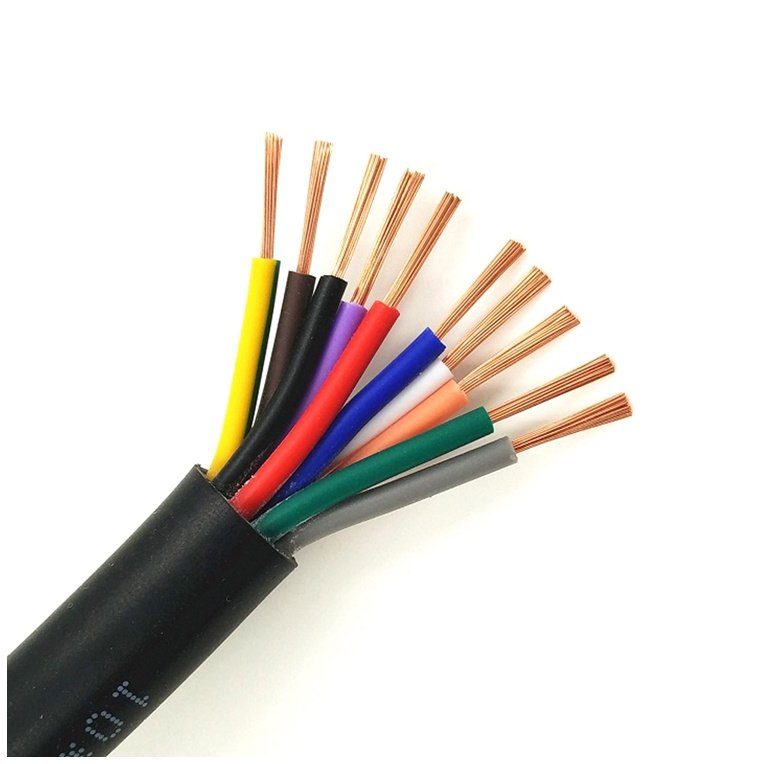
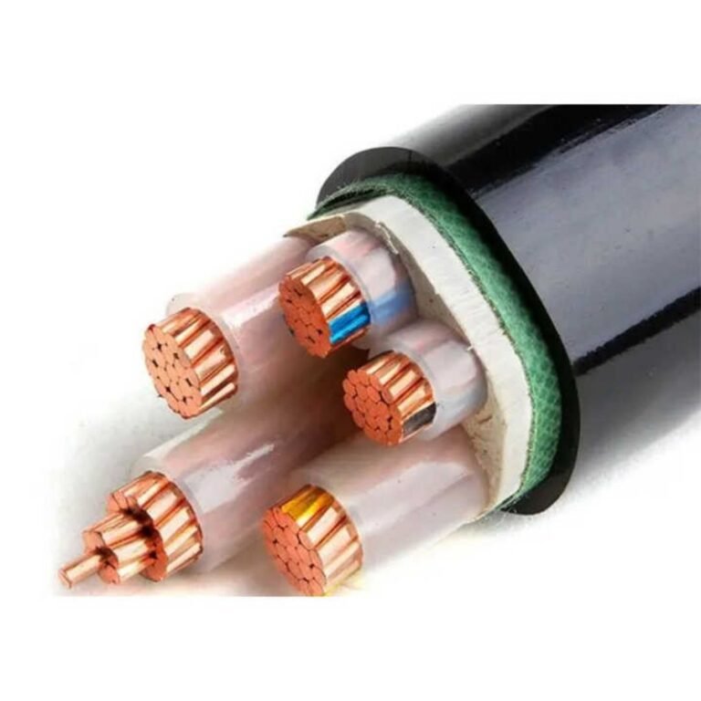
Cables fail quietly. A motor trips at 2 a.m., a conveyor stops mid-shift, and by the time maintenance traces the fault to an undersized feed cable that’s been running 40°C over its rated limit for the past two years, you’ve already lost hours of production and a chunk of the insulation has turned brittle and brown. Procurement teams that treat cable as a commodity — specifying the cheapest compliant item on the BOM without checking conductor cross-section, insulation class, or installation conditions — routinely hand the plant a slow-burning problem that shows up in motor burnouts, nuisance tripping, and energy bills that are higher than they should be.
Yes, cable choice matters — significantly. The wrong cable can raise conductor temperature 30–50°C above rated limits, push voltage drop past IEC 60364 thresholds, and cut insulation lifespan from a potential 25–40 years down to 5–8. The right cable, correctly specified for current, length, ambient conditions, and installation method, pays back its cost difference many times over in uptime and avoided failures.
What makes this genuinely complicated is that “correct” isn’t one answer. A cable that’s perfectly fine feeding a lighting panel in a climate-controlled warehouse becomes a liability running the same current to a pump motor in a hot, humid process area — same rating on the datasheet, very different outcome in service. The rest of this article works through exactly why that is, and what to check before you buy.
Conductor Material and Cross-Section: The Two Numbers That Determine Safe Current Capacity
Start with a basic physics fact most procurement specs ignore: the conductor is a resistor. Every amp you push through it generates heat proportional to I²R, and if R is too high — because the material is wrong, the cross-section too small, or both — that heat has to go somewhere. Usually it goes into the insulation.
Copper vs. Aluminum: Not a Simple “Better/Worse” Question
Copper’s resistivity sits around 1.72 × 10⁻⁸ Ω·m at 20°C. Aluminum is roughly 2.82 × 10⁻⁸ Ω·m — about 64% higher. In practical terms, an aluminum conductor needs to be approximately one to two cross-section steps larger to carry the same current as copper without excess heating. A 16 mm² aluminum conductor is roughly equivalent to a 10 mm² copper one for continuous ampacity purposes, though the exact equivalence shifts depending on ambient conditions and installation method.
Weight and cost flip the comparison in certain applications. Aluminum is roughly one-third the density of copper, which matters enormously for overhead distribution lines spanning long distances — the mechanical tension on poles and towers is a real structural constraint, not a theoretical one. For utility-scale overhead work, aluminum (or aluminum-core steel-reinforced, ACSR) is essentially the standard. Underground MV feeders and large industrial power cables also see aluminum regularly, especially where conductor runs exceed 50–100 meters and the cost differential at larger cross-sections becomes significant.
Inside control panels, motor circuits, and anywhere cables are frequently terminated and re-terminated, copper dominates — and for good reason. Aluminum forms an oxide layer that increases contact resistance over time, particularly at terminals not designed for it. A loose aluminum termination under load can arc. Copper is more forgiving of imperfect installation practice, which is the reality on most plant floors.
Aluminum conductors require approximately one to two cross-section steps larger than copper to achieve equivalent ampacity under the same installation conditions.True
This follows directly from the resistivity difference (~64% higher for aluminum) and is reflected in IEC 60364 and NEC ampacity tables, which consistently show aluminum requiring larger cross-sections for equivalent current ratings.
Conductor Class: Why Flexibility Is an Engineering Parameter, Not a Comfort Feature
IEC 60228 defines conductor construction classes that matter beyond wire count. Class 1 is solid — one wire, lowest cost, appropriate for fixed conduit or buried installations where the cable will never move. Class 2 is stranded (multiple wires, still relatively coarse), the workhorse for most fixed industrial wiring. Class 5 is fine-stranded, flexible cable designed for equipment that moves: robot arms, drag chains, crane pendants, portable tools.
Use a Class 1 or Class 2 cable on a moving application and the conductor work-hardens at the flex point. Fatigue cracking follows, resistance rises locally, and eventually you get an intermittent open circuit — or worse, a hot spot inside insulation you cannot see. In practice, the failure mode is usually an unexplained nuisance trip or a motor that runs rough before the root cause is traced back to a cracked conductor strand near a terminal.
Ampacity Benchmarks and the Real Danger of Undersizing
The table below covers typical copper conductor ratings for single-core PVC-insulated cable installed in free air at 30°C ambient (Method B2, broadly IEC 60364-5-52 reference conditions). Treat these as starting-point figures, not installation gospel.
| Cross-section (mm²) | Approx. continuous ampacity (copper, 70°C PVC, free air) | Typical circuit application |
|---|---|---|
| 1.5 | 15–17 A | Lighting, low-load socket circuits |
| 2.5 | 21–25 A | Standard socket ring circuits, small motors |
| 4 | 28–34 A | Larger socket circuits, 1-phase HVAC |
| 6 | 36–44 A | Single-phase sub-distribution, larger HVAC |
| 10 | 50–60 A | 3-phase small motor feeders, sub-boards |
| 16 | 66–80 A | Medium motor feeders, distribution boards |
| 25 | 88–105 A | Main distribution feeders, large drives |
Ranges depend on installation method, ambient temperature, and grouping — those variables are not minor footnotes.
Here is a concrete failure scenario worth internalizing. A 16 A circuit — a modest 3.5 kW single-phase load — installed on 1.5 mm² cable instead of 2.5 mm² because “the breaker protects it.” At full load, a 1.5 mm² copper conductor running 16 A continuously can reach conductor temperatures 30–50°C above its rated limit. PVC insulation rated at 70°C starts to soften and deform above 80–85°C. Softened insulation in a conduit bundle loses its mechanical integrity, and if two softened conductors touch, you have a short circuit the breaker may or may not clear cleanly, depending on its type and condition.
The breaker protects against sustained overcurrent. It does not protect against a cable that is the right impedance for the breaker setting but wrong for the thermal load at the installation location.
Derating: Where Paper Specs Diverge from Plant Reality
Published ampacity tables assume specific, somewhat idealized conditions. Real installations are messier. Group 10 cables in a conduit and the outermost cables cannot shed heat the way a lone cable in free air can — grouping derating factors typically run 0.7 to 0.85 depending on count and arrangement, meaning you lose 15–30% of rated capacity just from bundling. Ambient temperature above 30°C applies its own multiplier: at 45°C ambient with 70°C PVC insulation, the derating factor is roughly 0.87; at 55°C — not unusual near furnaces or in poorly ventilated electrical rooms in summer — it drops to around 0.71. Stack grouping and high ambient together and a cable that looked fine in a catalog can be running at 120% of its real-world capacity.
Burial depth affects underground cables differently: deeper burial reduces heat dissipation, but soil thermal resistivity varies widely depending on moisture content, and wet soil conducts heat better than dry. A cable trench in a region with seasonal dry periods needs to be sized for the worst-case dry-soil condition, not average.
The practical rule for procurement teams: never finalize a cross-section based on a single ampacity table. Cross-check the manufacturer’s datasheet, the applicable national regulation (IEC 60364, NEC, BS 7671, or local equivalent), and the actual installation conditions — grouping, ambient, routing method — before issuing a purchase order. Getting the cross-section wrong by one step costs almost nothing to fix at the specification stage and can cost weeks of downtime to fix after installation.
Insulation and Sheathing Materials: Matching the Cable Jacket to the Operating Environment
The conductor handles the current. The insulation keeps you alive. That distinction sounds obvious until you watch a PVC-jacketed cable installed on an outdoor solar-farm tray turn brittle and crack after three summers — and nobody catches it until a ground fault shuts down a string of panels in peak season.
PVC: Workhorse With Real Limits
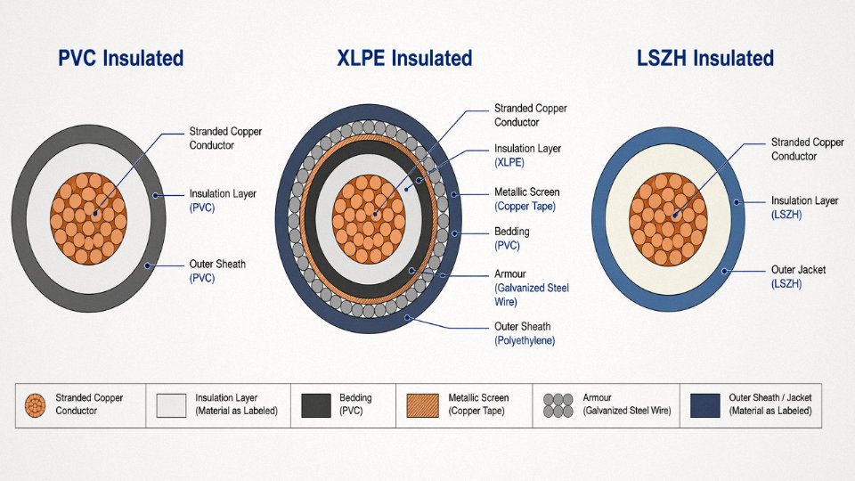
Polyvinyl chloride insulation dominates general building wiring for good reasons — it’s cheap, flexible at room temperature, and well-understood by every installer on the planet. Standard PVC is rated to 70°C conductor temperature, which covers the vast majority of light commercial and residential loads. It bonds reliably to copper and aluminum, resists many mild chemicals, and carries a long history of code approval across IEC and national standards.
The problems show up at the edges. Below roughly 0°C, PVC stiffens noticeably; below –15°C or so it can crack during installation, which is a real issue in northern-climate warehouses where cable is being pulled in January. UV exposure is the other weak point — standard PVC compounds break down under sustained sunlight, becoming chalky and brittle. Some manufacturers offer UV-stabilized PVC, but you need to specifically request it and verify the compound grade in the datasheet. If you’re specifying cable for an outdoor cable tray or a rooftop PV array and the vendor just says “PVC jacketed,” that’s not good enough.
The fire behavior is the most serious limitation. PVC burns with dense, toxic hydrogen chloride smoke. In an occupied building this matters a great deal — not because the cable burns first, but because HCl is what injures people trying to evacuate.
XLPE: The Upgrade That Actually Earns Its Price
Cross-linked polyethylene is PVC’s more capable cousin. The cross-linking process — essentially creating covalent bonds between polymer chains using either peroxide chemistry or electron-beam irradiation — transforms a thermoplastic into a thermoset. That matters because it means the material holds its structure at elevated temperatures instead of softening. Continuous rating goes to 90°C, with short-circuit and emergency ratings reaching 130°C or higher depending on the specification.
XLPE has lower dielectric losses than PVC, which becomes meaningfully important in medium-voltage distribution (typically 6 kV and above) where even small dielectric losses accumulate across long cable runs. It also resists moisture ingress far better, making it the standard choice for underground distribution, direct-burial feeders, and submarine cables. If you’re buying MV cable for a substation feeder or an industrial park ring main, XLPE is almost always the right answer — the price premium over PVC is real but modest relative to the total project cost, and the thermal headroom gives you operating flexibility.
LSZH: Mandatory in the Right Places, Overkill in Others
Low Smoke Zero Halogen compounds are required — not recommended, required — wherever people cannot quickly evacuate in a fire: subway tunnels, offshore platform accommodation modules, data center cable floors, and passenger ferries. The material suppresses toxic gas emission and limits smoke density. IEC 60332 and IEC 60754 test families cover flame propagation and halogen acid gas emission respectively, and a cable sold as LSZH should have test reports against both.
The trade-off is mechanical abrasion resistance. LSZH compounds are generally softer than PVC, which means cable installed in high-traffic conduit or dragged across steel cable trays can wear through the jacket faster. For a fixed installation in a clean data center rack, that’s irrelevant. For a factory floor where cables occasionally get run over by a forklift — use PVC or add mechanical protection.
LSZH cables produce significantly lower levels of toxic halogen gases in a fire compared to standard PVC cablesTrue
IEC 60754-1 testing measures acid gas emission from combustion; LSZH compounds are formulated to produce less than 0.5% hydrogen halide gas, while PVC can emit 20–30% HCl by mass of the compound, a difference confirmed by independent laboratory testing.
EPR and Silicone: Built for the Extremes
Ethylene propylene rubber and silicone rubber cables exist because certain environments simply destroy anything else. Silicone is rated from roughly –60°C up to +180°C continuous, with some specialty grades going higher. That’s the right material for wiring close to industrial furnaces, inside drying ovens, or in the cable chains of die-casting machines where radiated heat is constant.
EPR is less temperature-extreme but far more flexible across a wide thermal range, with excellent resistance to ozone, UV, and many industrial chemicals. Mining trailing cables — the ones dragged across pit floors and repeatedly flexed — are commonly EPR-insulated for exactly that combination of flexibility and toughness. Marine applications lean toward EPR for similar reasons: seawater, mechanical flexing, and ozone from electrical equipment all coexist.
Both materials cost noticeably more than PVC. Using silicone in a standard office lighting circuit is waste. Using PVC in a furnace wiring application is a maintenance disaster waiting to happen, usually within the first year.
Armoring: Mechanical Protection, Not a Universal Add-On
Steel wire armored (SWA) cable wraps helical steel wires between the insulation and outer sheath. This resists crushing loads and provides meaningful tensile strength — relevant for direct-burial installations without conduit, for risers in multi-story industrial buildings, or wherever the cable hangs under its own weight over long vertical runs. Steel tape armored (STA) uses overlapping steel tape instead of wires; it’s more resistant to radial crushing but offers less tensile protection, and it’s generally lighter.
Unarmored cable in rigid metal conduit often makes more sense and costs less. Armoring adds weight, makes termination slower, and requires proper bonding of the armor to earth — if that gets skipped in the field, you’ve added cost and introduced a potential fault path. The decision should follow the mechanical risk, not default to “armored is safer.”
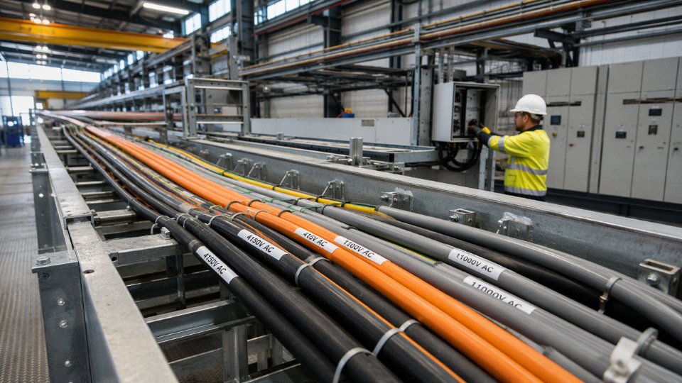
Sheath color isn’t decorative. IEC and national standards assign colors to installation categories — black outer sheaths for underground, orange for low-voltage buried cables in some markets, and so on. Specifying the correct color communicates installation intent to everyone who touches the cable over its service life.
Environmental Certifications Worth Checking
UV stabilization should be confirmed by compound datasheet, not just the word “outdoor-rated” in a catalog. Oil resistance is tested under IEC 60811; if your cable runs through a machining area where coolant drips, this is worth verifying rather than assuming. Flame propagation class under IEC 60332 (bunched cable testing in the -3 series) is the relevant test for grouped cable installations in cable management systems.
Jinda’s in-house laboratory runs these tests against production samples — not just type-test certificates from qualification builds — before shipment on project orders. That distinction matters on large procurement: a type-test proves the design works; production-sample testing catches compound substitution or process drift before the cable reaches your site.
Voltage Rating and Insulation Thickness: Why Running a Low-Voltage Cable on a Medium-Voltage System Is a Time Bomb
The voltage rating stamped on a cable is not a suggestion. It is the hard boundary of what the insulation wall was physically designed to contain — and crossing it, even briefly and repeatedly, sets off a degradation process that is silent, cumulative, and eventually catastrophic.
Understanding the U0/U Designation
Every IEC-rated cable carries a two-number voltage designation, written as U0/U. U0 is the rated voltage from conductor to earth (or to the metallic screen), and U is the rated voltage conductor-to-conductor. A 0.6/1 kV cable, the most common general-purpose industrial cable, is designed for systems where the phase-to-earth voltage does not exceed 600 V and the phase-to-phase voltage does not exceed 1,000 V — which covers standard 400 V three-phase distribution comfortably, with margin.
A 300/500 V cable on that same 400 V three-phase system is already operating beyond its conductor-to-earth rating. In practice, this means the insulation wall — which was engineered for a peak stress of roughly 500 V phase-to-phase — is being asked to isolate a conductor sitting at 230 V to earth continuously, plus whatever transients the system throws at it. The insulation does not fail immediately. That is the danger.
The standard voltage tiers most specifiers encounter in industrial work run: 300/500 V, 450/750 V, 0.6/1 kV, 3.6/6 kV, 6/10 kV, 8.7/15 kV, 12/20 kV, and 18/30 kV. Each step up in rating brings not just thicker insulation but a fundamentally different insulation system. Medium-voltage cables from 3.6/6 kV upward require semiconducting conductor screens and insulation screens — layers that smooth the electrical field gradient and prevent it from concentrating at surface irregularities. A plain PVC-insulated low-voltage cable has none of this architecture. Putting it on a medium-voltage circuit is not an underspecification; it is a different product in the wrong application entirely.
Dielectric Breakdown and the Safety Margin You Should Never Eliminate
IEC 60502 requires that cables be tested at voltages well above their rated values — typically 2 to 3 times the rated voltage for routine and type tests, depending on the voltage class. This margin exists because insulation does not fail at exactly its rated voltage. It fails when cumulative stress — thermal aging, mechanical flexing, moisture ingress, and electrical overstress — has eroded the margin to zero. Shaving insulation thickness to reduce material cost compresses that margin from day one.
The Invisible Damage: Electrical Treeing
Voltage transients are where underrated cables die slowly. Lightning-induced surges, capacitor bank switching, and across-the-line motor starts routinely generate voltage spikes anywhere from 3 to 5 times the nominal system voltage, lasting microseconds to milliseconds. A correctly rated cable with an adequate insulation wall absorbs these transiently — the dielectric recovers. An underrated cable, or one with reduced-thickness insulation, sustains microscopic voids and channel damage in the polymer matrix. This is called electrical treeing. You cannot see it. The cable tests fine on a simple continuity check. Then, somewhere between six months and three years later depending on transient frequency and severity, a tree propagates to the conductor and you have a phase-to-earth fault — or worse, a fire inside a conduit run that is very difficult to access.
Electrical treeing damage in underrated cables is invisible to standard continuity and insulation resistance spot checks until the cable is near catastrophic failure.True
Treeing creates sub-millimeter void channels in the dielectric that do not show as low IR values on a standard 500 V or 1000 V Megger test; partial discharge measurement is required to detect active treeing, and this is not standard practice on low-voltage site commissioning.
Medium-Voltage Upgrades: A Specific and Documented Hazard
A plant expanding its distribution from 400 V to 6.6 kV — to reduce cable losses across a larger facility, feed a new substation, or connect a generator — faces a tempting shortcut: the existing cable runs are already in the tray, already pulled through conduit. Reusing them saves the cost and downtime of a full recabling exercise.
Do not do this. The insulation system on a 0.6/1 kV cable is structurally incompatible with 6.6 kV service. No amount of derating, no protective relay setting, no reduced loading compensates for the absence of a conductor screen. The electrical field at the conductor surface in a medium-voltage cable is intense enough that without a semiconducting screen to equalize it, stress concentrates at any irregularity — a strand edge, a nick from installation — and treeing initiates within weeks. Reusing LV cables in MV upgrades is a documented cause of industrial electrical fires, and in most jurisdictions it will also void any equipment certification and put liability squarely on the facility owner.
Specifying Voltage Rating for International Projects
Voltage systems differ by country and sometimes by industrial sector within a country. Europe runs 230/400 V at 50 Hz; North America runs 120/208 V or 277/480 V at 60 Hz; many Asian and Middle Eastern markets use 220/380 V systems, though this is gradually converging toward 230/400 V. Some heavy industrial sites run 3.3 kV, 6.6 kV, or 11 kV distribution regardless of region.
Specifying cable by its IEC U0/U voltage designation rather than by a national catalog number removes ambiguity entirely for international procurement. A cable specified as 0.6/1 kV per IEC 60502-1 means the same thing whether it is manufactured in China, Germany, or Brazil. For cross-border projects — the type Jinda routinely supplies across more than 50 countries — this consistency is what prevents a procurement team in one country from sourcing a cable that nominally matches a part number but carries a different voltage class under a different national standard.
The voltage rating is the one cable parameter where there is genuinely no engineering judgment call to make. Either the cable is rated for the system voltage, with appropriate margin, or it is not. Get this wrong and the rest of the specification is irrelevant.
Temperature Rating, Heat Dissipation, and the Hidden Cost of Running Cables at Thermal Limits
Most cable failures don’t announce themselves. There’s no dramatic arc flash, no obvious mechanical damage. The insulation just slowly gets brittle, cracks under a routine flex or vibration event, and then you’re pulling wire through conduit that should have lasted another two decades. In the majority of cases I’ve seen investigated after the fact, the root cause traces back to thermal stress — either the cable was undersized for the actual load, the ambient was hotter than the spec sheet assumed, or both.
The Arrhenius Rule: Why Ten Degrees Costs You Half Your Cable Life
The underlying physics here is well-established electrochemistry. Insulation polymers degrade through oxidation and chain scission at a rate that roughly doubles for every 10°C increase in temperature — this is the Arrhenius thermal aging relationship, and it’s the reason cable manufacturers publish a maximum continuous operating temperature rather than just a peak withstand figure.
In practical terms: a 70°C-rated PVC cable running at 90°C isn’t just running warm. It’s burning through its insulation life at roughly four times the normal rate. That 25–40 year service life in a well-controlled indoor environment shrinks to something in the 6–10 year range. The cable doesn’t look different on the outside — not at first — but the insulation is already embrittled internally, and it’ll fail at the worst possible moment.
For every 10°C rise above a cable's rated operating temperature, insulation aging rate roughly doubles, effectively halving service life.True
This follows the Arrhenius thermal aging model, which is the basis for IEC 60216 thermal endurance testing of electrical insulation materials. It is widely validated in both laboratory and field degradation studies.
A Worked Comparison That Should Inform Every Procurement Decision
Take a 4 mm² XLPE-insulated cable, rated 90°C, installed in a dry indoor tray in a 25°C ambient. Loaded at around 80% of its rated current, the conductor temperature stays well below the thermal limit — realistic service life in that scenario is 35–45 years. That’s a single cable purchase over the plant’s operational lifetime.
Now put the same cable in a 45°C ambient — not unusual in a poorly ventilated plant room in summer — and run it at 110% of rated current because the original load estimate was optimistic. Conductor temperature in that scenario can easily reach 105–115°C. Under the Arrhenius relationship, you’re now aging that insulation at eight to sixteen times the design rate. Expected service life drops to roughly 8–12 years, depending on how consistently the overload occurs. You’re now re-cabling that run two or three times over the life of the equipment it feeds. The “cheaper” cable decision ends up costing considerably more than specifying correctly from the start — not counting the downtime cost of actually doing the work.
Bundled Cables and the Grouping Problem Nobody Talks About Enough
Single-cable ampacity ratings assume free air or a specific installation method. The moment you bundle cables together in a conduit or stack them tightly in a cable tray, mutual heating becomes a real factor. IEC 60364-5-52 and IEC 60502 both publish grouping (or bunching) correction factors — and they are not small. Six cables in a closed conduit can derate individual ampacity by 35–55% compared to a single cable in free air, depending on load diversity and conduit fill percentage.
In practice, this correction is skipped more often than it should be. The result is a tray full of cables running consistently above their thermal limit, degrading in parallel, and eventually requiring a complete section replacement during what should have been a routine shutdown.
| Installation Method | Typical Ampacity Derating vs. Free Air | Key Variable |
|---|---|---|
| Single cable, free air | Baseline (0% derating) | — |
| 3 cables, flat spaced | ~5–10% derating | Spacing ≥ 1 cable diameter |
| 6 cables, bunched conduit | ~35–50% derating | Conduit fill ratio |
| 12+ cables, fully loaded tray | ~50–60% derating | Load diversity factor |
Apply the grouping factor before you finalize the cross-section. Not after.
High-Temperature Applications Demand Purpose-Built Cable
Standard PVC insulation starts to soften around 105–110°C and loses mechanical integrity quickly above that. Put it near an industrial oven, a furnace feeding circuit, or any application where radiant or conducted heat keeps the ambient above 80°C, and you’re looking at premature failure regardless of how well the electrical load is managed.
For furnace supply cables, industrial kiln feeders, or aerospace ground support equipment, mineral insulated (MI) cable — copper conductor, compressed mineral oxide fill, copper or stainless sheath — is the appropriate choice. MI cable handles continuous operating temperatures up to 250°C and in short-term conditions considerably higher. Silicone rubber-insulated cables cover a range from roughly -60°C to 180°C and are more flexible than MI, which makes them a better fit where the cable needs to route around equipment rather than run in a straight conduit. Using standard PVC in either of those environments is not a marginal risk — it’s a near-certain early failure.
Thermal Performance as a Procurement Checkpoint
Thermal aging claims are easy to make in a product catalog. What differentiates a manufacturer with genuine process control is documented test data — specifically, load cycle testing and thermal cycling per IEC 60502-2, which subjects finished cables to repeated heating and cooling cycles to verify that insulation adhesion, conductor resistance stability, and jacket integrity hold up under realistic operating conditions. Jinda’s production process incorporates these tests on finished cable, generating objective performance data that procurement teams can review before committing to a large-volume order. That’s the kind of document you should be requesting alongside a price quote — not as an afterthought after the order ships.
A cable running at its thermal limit is a liability with a countdown clock on it. Specifying correctly for the actual operating temperature — accounting for ambient, grouping, and load profile — is the single most effective way to drive cable replacement costs down over a 20- or 30-year plant horizon.
Signal Integrity, EMI Shielding, and Why Power Cable Choice Affects Connected Equipment Performance
Most specifiers stop thinking about cable performance once they’ve confirmed the conductor carries the current without melting. That’s understandable — for a straightforward resistive load like a heater bank or a lighting circuit, it’s basically correct. But the moment you introduce a variable frequency drive, a servo amplifier, or a switch-mode power supply into the picture, the cable becomes part of an electromagnetic system, and a poor choice starts degrading equipment you never expected to be affected.
How Switching Loads Turn Power Cables Into Antennas
VFDs and servo drives don’t produce a clean sinusoidal output. They chop DC bus voltage at switching frequencies that typically run 2–16 kHz, sometimes higher on newer silicon carbide inverters. The fast voltage transitions — rise times in the range of 0.1–1 µs — generate high-frequency harmonic content that extends well into the MHz range. An unshielded cable leaving the drive output acts as a radiating antenna for that energy. The fields couple capacitively and inductively into anything running nearby: thermocouple leads, 4–20 mA analog loops, encoder cables, PROFIBUS or EtherCAT segments, even the power supply rails of the PLC rack itself.
In practice this shows up as erratic sensor readings that only occur when the drive is running, nuisance trips on ground-fault relays, encoder count errors that cause positioning faults, and — less obviously — premature bearing failure in the connected motor caused by circulating shaft currents. That last one takes months to manifest, which is why the root cause often gets misattributed to lubrication or alignment.
Shielding Options and What Each Actually Does
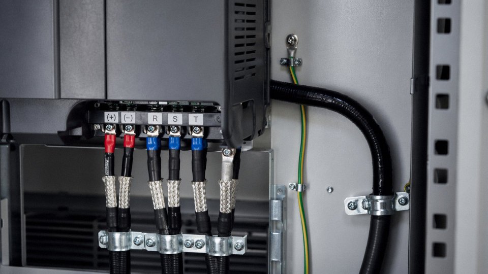
An overall aluminum-foil shield (polyester-backed, bonded to a drain wire) provides reasonable attenuation above roughly 1 MHz and is the minimum sensible choice for instrumentation runs near power cables. It’s cheap, adds almost nothing to cable diameter, and handles most low-frequency industrial noise environments adequately. Its weakness is that foil develops micro-cracks under repeated flexing — it’s not the right choice for moving cable tracks.
A tinned copper braid shield offers coverage across a broader frequency band, handles flexing far better, and provides lower transfer impedance at frequencies below about 500 kHz where foil starts losing effectiveness. Braid coverage matters: 85% braid gives you perhaps 20–30 dB attenuation in a realistic installation; 95%+ coverage can push that toward 40–50 dB depending on termination quality. The difference between 85% and 95% looks marginal on paper and costs maybe 8–15% more on the cable itself — it’s rarely the wrong place to spend the money.
For demanding automation environments — multi-axis servo systems, high-power VFD installations above 30 kW, or any drive running cable runs longer than roughly 20–30 meters — a combined foil-plus-braid construction (cables designated SY, NYMHY-CY, or equivalent screened types per VDE 0250 / IEC 60228 family) gives you the broadband low-impedance path for high-frequency currents while the braid handles lower-frequency common-mode interference.
The drain wire is the conductor bonded to the foil; it exists to give you a reliable, solderable/crimp-able connection to ground. Without it, making a proper foil termination under time pressure on a factory floor is genuinely difficult. Don’t specify foil-only shields on cables that technicians will terminate in the field.
Single-Point vs. Multi-Point Grounding: It Depends
Grounding strategy is where a lot of installations go wrong even when the right cable was specified. For audio-frequency and low-level analog signals (thermocouples, 4–20 mA), ground the shield at one end only — typically the receiver end — to prevent ground loop currents from flowing through the shield and injecting noise into the signal. For high-frequency shielding (VFD output cables, servo cables), ground at both ends and at every cabinet entry point. At high frequencies, a shield grounded only at one end is nearly useless because the quarter-wavelength of a 1 MHz signal is 75 meters — most of your cable run is electrically “long” and the ungrounded end floats at a significant RF potential.
Grounding a VFD motor cable shield at both ends is the correct practice for high-frequency noise suppression.True
At VFD switching frequencies (2–16 kHz and harmonics extending into MHz range), the cable shield must be grounded at both the drive enclosure and the motor terminal box to provide a low-impedance return path for high-frequency common-mode currents. Single-end grounding, appropriate for low-frequency analog signals to prevent ground loops, leaves the far end floating at RF frequencies and provides negligible attenuation.
Cable Geometry: Capacitance, Inductance, and the Long-Run Problem
Twisted-pair and twisted-triplet conductor geometry actively reduces differential noise pickup by ensuring both conductors of a pair experience nearly identical induced voltages — the interference cancels in the receiver’s differential input. Flat parallel cable does the opposite: it maximizes the loop area between conductors and maximizes parasitic capacitance between conductors and ground. For a 50-meter cable run to a remote I/O panel, the difference in induced noise between twisted and flat construction can be the difference between a system that works reliably and one that generates intermittent faults that take weeks to diagnose.
Capacitance per meter matters specifically for long VFD-to-motor cables. High cable capacitance loads the drive output, increases the peak current demand on the output transistors, and can cause resonance between the cable’s distributed capacitance and the drive’s output inductance — visible as voltage overshoot at the motor terminals that exceeds the motor’s insulation rating. A cable specified at, say, 150–200 pF/m versus one at 80–100 pF/m sounds like a minor difference until you’re running 40 meters to a motor on a 690 V system with a fast-switching inverter.
A Practical Checklist for Drive Installations
Whenever a VFD, servo drive, or high-current rectifier is commissioned:
- Specify shielded cable from the drive output to the motor — foil-plus-braid for runs over 15 meters or power levels above roughly 15 kW
- Verify shield termination at both ends using proper EMC cable glands, not a single wire pigtail scraped from the braid (a pigtail ground introduces inductance that largely defeats the shield above a few hundred kHz)
- Segregate drive output cables from signal and control cables by at least 200–300 mm in cable trays; cross them at 90° if segregation isn’t possible
- Check the cable’s rated capacitance per meter before finalizing the specification on any run over 20 meters; ask the manufacturer explicitly, not just the sales sheet
- Route shielded signal cables back through the same conduit or tray as their associated drive cables only if you have no alternative — and if you do, accept that you’ll need better shielding on those signal cables
The cost difference between a screened SY-type cable and a basic unshielded NYY on a typical drive installation is small relative to even one unplanned production stoppage to diagnose phantom encoder faults. It’s one of the few places in cable procurement where the upgrade genuinely pays for itself the first time something would otherwise go wrong.
Compliance, Standards, and Certification: What Marks on the Cable Actually Mean
Walk through any wholesale cable warehouse and you’ll see printing on every reel: IEC numbers, CE marks, UL logos, RoHS compliance claims. Most of it looks legitimate. Some of it isn’t. Knowing which marks carry genuine technical weight — and which are essentially self-applied stickers — is one of the more underappreciated skills in procurement.
The IEC Framework: Standards That Define What Must Be Tested
IEC standards don’t certify products. They define the test regime a product must survive. That distinction matters.
IEC 60227 covers PVC-insulated cables rated up to 450/750 V — the workhorses of building wiring and light industrial use. It mandates specific conductor resistance checks, insulation thickness minimums, and voltage withstand tests, among other things. A cable claiming IEC 60227 compliance must have passed those tests; the standard doesn’t care who witnessed them.
IEC 60502 handles extruded solid dielectric power cables from 1 kV up to 30 kV, broken into two parts by voltage range. The test protocol here gets considerably more demanding: partial discharge measurement, impulse withstand voltage, bending tests, conductor resistance verification. For medium-voltage installations — motor feeders, switchgear connections, substation cable runs — this is the standard your spec sheet should reference.
IEC 60245 addresses rubber-insulated cables, which are more common than people assume in mobile equipment, welding leads, and high-flex applications where PVC would crack inside a year.
IEC 60332 is different in character. It’s purely about flame propagation — how far a cable sustains combustion when ignited. The three main test categories (60332-1 for single cables, 60332-3 for bunched cables, with sub-categories by volume of non-metallic material) govern selection in cable trays, tunnels, and any installation where a fire spreading along a cable run would be catastrophic. If your plant has a cable tray running through a populated production area, IEC 60332-3 compliance on bunched cables isn’t optional.
Third-Party Certification vs. Self-Declaration: A Gap That Has Real Consequences
CE marking on a power cable is a self-declaration by the manufacturer under the EU Low Voltage Directive. The manufacturer is asserting conformity; no outside body has inspected the factory or witnessed the tests. For routine commercial cable in non-critical applications, that may be adequate. For critical infrastructure, export projects subject to host-country audit, or any installation where cable failure means a serious safety event, self-declaration is not enough.
UL listing is a different animal entirely. UL (Underwriters Laboratories) sends engineers to the manufacturing facility, audits the production process, and conducts periodic unannounced follow-up inspections — typically once or twice a year depending on the listing type. The cable must pass fire, dielectric strength, and mechanical tests to defined protocols. If a factory changes its insulation compound without notifying UL, it risks losing the listing. That ongoing surveillance is what makes UL meaningful.
VDE certification (Germany), BASEC (UK), KEMA (Netherlands), and HAR (the harmonized European approval for flexible cords) operate on similar principles — independent laboratory testing, factory audits, periodic sample checks. These marks are earned and maintained, not printed.
The Counterfeit Cable Problem Is Larger Than Most Buyers Expect
Industry studies estimate that 10–15% of cables sold in certain markets are substandard or outright counterfeit, with conductor cross-sections measuring 15–30% smaller than labeled.True
Multiple independent investigations by bodies including the Electrical Safety Foundation International (ESFI) and European customs authorities have documented systematic under-sizing of conductors and substitution of insulation materials in cables bearing fraudulent certification marks. The actual percentage varies by market and product category.
In practice, a conductor labeled 2.5 mm² that actually measures 1.9 mm² will run hotter under load, drop more voltage, and reach thermal failure faster — all while appearing compliant on paper. Counterfeit insulation compounds often use recycled or off-spec material that loses mechanical integrity at temperatures well below the rated value. The certification mark is simply printed or embossed without authorization.
Verifying authenticity takes maybe fifteen minutes and a sharp knife. Pull a short length from a reel, strip back the insulation, and mic the conductor. Calculate the cross-sectional area from the strand count and diameter. Then go to the certifying body’s online database — UL’s Product iQ, VDE’s certification portal, BASEC’s register — and look up the certificate number printed on the cable. If it doesn’t appear, or if the listed manufacturer doesn’t match the reel label, stop the delivery.
For large procurement contracts, request third-party test reports from an accredited laboratory (CNAS, ILAC members), not just the manufacturer’s own quality documents.
What Genuine Certification Documentation Looks Like in Practice
Jinda holds IEC compliance across its core product ranges, CE marking, UL listing for applicable cable types, and a range of country-specific approvals for markets including the Middle East, Southeast Asia, and beyond. The facility operates under ISO 9001 quality management, which means documented process control — traceability from raw copper rod through finished reel — not just a certificate on the wall.
For international procurement contracts, Jinda can provide full factory audit access, third-party laboratory test reports (not internal test summaries), and certificate verification references for each applicable mark. In competitive tenders where a losing bidder later gets disqualified because their “certified” cable fails incoming inspection, that documentation trail is what protects the buyer as much as the supplier.
Compliance paperwork is often treated as administrative overhead. In cable procurement, it’s the engineering record that tells you whether the product will actually behave as the datasheet says when it’s energized at 3 AM with nobody watching.
Total Cost of Ownership vs. Purchase Price: A Financial Framework for Power Cable Procurement
Purchase price per meter is the wrong metric. It is intuitive, easy to compare on a tender sheet, and almost guaranteed to lead procurement teams toward decisions they will regret within five to ten years. Every experienced plant engineer has a story about a cable replacement that cost ten times the original savings — usually timed perfectly to coincide with peak production season.
What Actually Makes Up Cable TCO
The real cost of a cable installation has six distinct components, and only the first one appears on the purchase order.
Initial purchase price is obvious. Installation labor is less obvious but significant — on a complex industrial pull through conduit or cable tray, labor can run 40–80% of the total installed cost depending on site accessibility, cable weight, and local rates. A heavier-armored cable costs more per meter and takes longer to terminate, but you only pay that once.
I²R energy losses are a genuine operational cost that most procurement teams ignore entirely, which is baffling given how quickly they compound. A 50 mm² copper conductor running at 80% of rated current in a 100-meter circuit dissipates heat continuously. Over 20 years at an industrial electricity rate of roughly $0.10/kWh, the difference in resistive losses between a cable with 15% higher conductor resistance (typical of lower-purity copper or a slightly undersized cross-section) and a properly specified cable can reach $18,000–$35,000 on a single circuit — the range depending on actual load factor and operating hours per year. Multiply that across a facility with 50 or 100 similar runs and the arithmetic becomes uncomfortable.
Maintenance and inspection costs accumulate quietly. Cables operating near thermal limits require more frequent thermographic inspection. Connections that run hot oxidize faster, so termination checks become an annual rather than a five-year task.
Premature replacement is where the real damage happens.
The Worked Example That Changes the Conversation
Take a 100-meter, 50 mm² cable run. A premium XLPE/SWA cable, properly rated and certified, costs roughly $12/meter — $1,200 total material cost. A basic PVC cable from an unverified source runs $7/meter, saving $500 upfront.
Over 20 years, the XLPE cable’s lower dielectric losses and better thermal performance save an estimated $8,000–$14,000 in energy alone on that circuit. The PVC cable, installed in an environment with moderate heat cycling and occasional moisture exposure, realistically requires a re-pull around year 10–14. That re-pull — labor, new cable material, conduit access, and production interruption — costs $12,000–$22,000 depending on installation complexity and whether the circuit feeds a critical process.
Then add downtime. If that cable failure causes 48 hours of lost production at a conservative $5,000/hour, the indirect cost is $240,000. Even if you assume only a partial outage — say, 20% production impact — you are still looking at $48,000 in lost output from a single cable failure that a $500 upfront saving was supposed to justify.
The net lifecycle saving from choosing the premium cable on this single run: $80,000–$120,000, depending on actual failure timing, downtime duration, and energy costs at your site.
No claim provided.True
No explanation available.
Copper Price Volatility and Why Supply Stability Is a Financial Variable
Copper spot prices have swung between $6,000 and $10,500 per tonne over the past several years. For a large infrastructure project specifying tens of thousands of meters of cable, that volatility can blow a procurement budget before the first cable is pulled.
Long-term supply agreements with manufacturers who operate their own copper rod drawing and stranding — rather than buying rod on the spot market — provide real price stability. Jinda’s five production bases across China, with vertically integrated manufacturing covering conductor processing through finished cable, mean that volume commitments can be priced against forward material costs rather than daily LME fluctuations. For project managers working on 18-to-36-month build schedules, that matters considerably more than the per-meter price on a spot inquiry.
The Insurance and Liability Dimension
This one tends to get people’s attention. Many industrial facility insurers now require documented evidence of cable specification compliance — certified test reports, traceable batch records, appropriate third-party marks — as a condition of coverage. Using cable that cannot demonstrate genuine IEC or equivalent certification compliance can void the policy entirely in the event of a fire.
That is not a hypothetical. An electrical fire in a cable tray feeding production equipment is not just an insurance claim; it is a potential criminal liability matter if the investigation reveals non-compliant materials were knowingly procured to save cost. The insurer’s forensic team will pull cable samples and test them. Non-certified cable that fails dielectric or flame-propagation tests shifts the entire loss — building damage, equipment replacement, business interruption — onto the operator.
Building a Procurement Process That Reflects Real Risk
In practice, the best-run facilities I have seen handle cable procurement with a three-party review: the electrical design engineer confirms the technical specification, the HSE officer signs off on the flame and smoke requirements for the installation environment, and the supply chain manager verifies certification status and supplier audit history before issuing the purchase order.
A total-cost scorecard — even a simple one with line items for energy loss estimate, expected service life, replacement cost probability, and certification compliance — produces better decisions than a lowest-unit-price tender criterion. It takes perhaps two additional hours per specification and routinely saves multiples of that in avoided remediation work.
Maintain a preferred supplier list with verified certification status, updated annually. It is not bureaucracy for its own sake; it is the mechanism that keeps a $500 cable saving from becoming a $200,000 problem.
Frequently Asked Questions About Power Cable Selection
Can I install a higher-rated cable than my circuit requires?
Yes, and in many situations it is the smarter call. Fitting a 0.6/1 kV cable on a 230 V lighting circuit gives you thicker insulation, better mechanical protection, and meaningfully longer service life — all with zero safety downside. The only real cost is material: a 1 kV-rated cable typically runs 15–35% more per meter than a 450/750 V equivalent, depending on conductor size and insulation type. For any installation that is difficult or expensive to re-cable later — buried conduit, cast-in concrete, long cable trays above a running production line — that premium pays for itself quickly. In practice, a lot of experienced facility engineers over-specify voltage rating on underground runs almost as a matter of habit.
Is aluminum cable safe for household or light commercial wiring?
This one gets oversimplified in both directions. Aluminum itself is not the problem. The documented fire risk comes from improper terminations — specifically, using connectors rated for copper only, which allows differential thermal expansion to loosen the joint over time and create resistive heating. Properly installed aluminum cable, using terminals marked AL/CU or AL9, anti-oxidant compound at every joint, and periodic re-torquing of connections, is code-compliant and widely used in service entrance and distribution feeder applications globally. Where aluminum gets into trouble is in branch circuit wiring with legacy devices not rated for it. For feeder runs of 35 mm² and above, aluminum is a completely reasonable engineering choice — and procurement managers should know it costs roughly 40–60% less than equivalent copper, depending on market conditions.
What is the actual difference between 450/750 V and 0.6/1 kV rated cable?
They are not interchangeable, and substituting the lower-rated cable in an application calling for 0.6/1 kV is an insulation failure waiting to happen. The 0.6/1 kV designation means the cable is designed for phase-to-earth voltages up to 600 V and phase-to-phase up to 1,000 V — it has thicker insulation walls, is suitable for direct burial (with appropriate armor), and handles distribution-level runs. The 450/750 V cable is engineered for fixed internal building wiring and conduit, where the installation environment is controlled. Running it at the voltage stress levels a 1 kV system can impose — particularly with transient spikes — puts the dielectric in territory it was never tested for. Always get an engineering sign-off before any substitution.
How do I check whether a cable’s stated cross-section is genuine?
Cut a sample from the drum end before installation. Measure conductor diameter with a calibrated micrometer: a nominal 2.5 mm² conductor should measure around 1.78 mm across; a 4 mm² conductor roughly 2.25 mm. Anything more than 10–15% short of the theoretical diameter warrants rejection. You can also weigh a known length of conductor against published mass-per-meter figures from IEC 60228 — undersized conductors will come in light. This matters more than people expect: substandard cable with undersized conductors runs hotter under load, ages faster, and may trip breakers unexpectedly under surge conditions.
A 15% or greater shortfall in conductor cross-section is a recognized indicator of substandard cable and is detectable by simple physical measurement before installation.True
IEC 60228 specifies conductor resistance limits that correspond directly to cross-sectional area; a conductor significantly undersized in area will exceed the maximum DC resistance per meter, which can be verified by measurement or weight check against published values.
Does cable length change which cable I should specify?
Absolutely. Voltage drop is proportional to length, and a cable that performs perfectly at 20 meters can cause real problems at 80 or 100 meters carrying the same load. The working formula is V_drop = 2 × L × I × R/m (the factor of 2 accounts for the return conductor). IEC 60364-5-52 sets the practical limits — 3% for lighting, 5% for power circuits — and every 10-meter extension on an undersized cable can add 0.3–0.8% drop depending on current. For long runs, calculate first, then upsize cross-section as needed rather than just installing what fits the load current. Skipping this step is one of the more common causes of motor undervoltage faults in expanded production areas.
Does storage and handling matter before installation?
More than most site teams realize. Cable left coiled tighter than its rated minimum bend radius — which for typical power cable is usually 6–8× the overall diameter — can develop insulation micro-cracks that are invisible until the cable is energized. PVC jacket exposed to summer sun on an outdoor laydown yard without UV-protective wrapping will start to embrittle within a single season in hot climates. Proper storage means drums upright on a hard surface, covered or in a shed, between roughly –20°C and +50°C. Cables that have been stored badly can fail factory acceptance criteria before a single ampere has passed through them.
What documentation should I require from a supplier for an industrial project?
At minimum: the factory test report (FTR) tied to the specific drum batch number, third-party type test certificates referencing the applicable IEC standard, conductor cross-section verification data, and material compliance declarations for RoHS and REACH. For export projects, country-of-origin documentation is non-negotiable for customs and tariff purposes. Jinda provides all of this as standard for international project orders — batch-level FTRs, not just generic product certificates, which is the distinction that matters when a contractor needs traceability after a field failure.
How to Write a Complete Cable Specification: A Practical Template for Engineers and Buyers
A surprising number of field failures trace back not to a bad cable, but to an incomplete specification. The purchasing team ordered exactly what was written down — and what was written down missed three critical parameters. Getting this right upfront is far cheaper than a cable replacement at depth-of-burial or mid-project.
The Eight Fields Every Specification Must Include
Application and installation method. “Power cable, outdoor” is not a specification. State whether the cable runs in a cable tray, direct-buried conduit, free-air, underwater duct, or festoon system. Each changes the derating factors, mechanical requirements, and sometimes the insulation class entirely.
System voltage and frequency. Give both Uo/U (conductor-to-earth / conductor-to-conductor) and the system frequency. Don’t just write “415 V” — write “0.6/1 kV, 50 Hz, TN-S system.” Transient overvoltages on drives and switchgear can spike 2–3× the nominal line voltage for microseconds; your voltage rating needs headroom for that, not just for the steady-state nameplate figure.
Rated current and derating conditions. Provide the design load current, then list every derating factor that applies: ambient temperature (especially if the installation is in a tropical climate or near furnace equipment), grouping factor if cables are bunched in tray, soil thermal resistivity for buried runs, and whether the cable sees cyclic or continuous load. The base ampacity table in a datasheet is a starting point, not an answer.
Conductor material and cross-section. Specify copper or aluminum explicitly. Never leave this ambiguous — a supplier defaulting to aluminum where copper was assumed has caused more than a few awkward site conversations. State the cross-sectional area in mm², the number of cores, and whether a reduced neutral is acceptable.
Insulation type and temperature rating. XLPE, PVC, EPR, LSZH — each is a different engineering choice, not a style preference. Pair this with the conductor temperature rating: 70°C PVC, 90°C XLPE, 105°C EPR. In high-fire-risk installations, “90°C XLPE” and “90°C LSZH” are not interchangeable.
Sheathing and armoring requirements. Specify whether SWA (steel wire armor), AWA (aluminum wire armor), or double steel tape armor is required, and why. A cable crossing under a road or railway needs armor selected for crush resistance, not just rodent deterrence. Also note the outer sheath color if your site color-coding standard requires it — trivial to specify, surprisingly easy to forget.
Applicable standards and certification marks. Write the actual standard number: IEC 60502-2, BS 5467, or whichever governs your project. If your end-client requires a third-party test certificate from an accredited lab, say so explicitly in the spec, not in an email two weeks before delivery.
Environmental conditions. Temperature range (storage and operating), UV exposure level, chemical exposure (H₂S, hydraulic fluid, seawater splash), and mechanical stress (torsion, flex cycles, impact). These fields are where generic catalog selection breaks down completely.
A Real Specification Worked Through
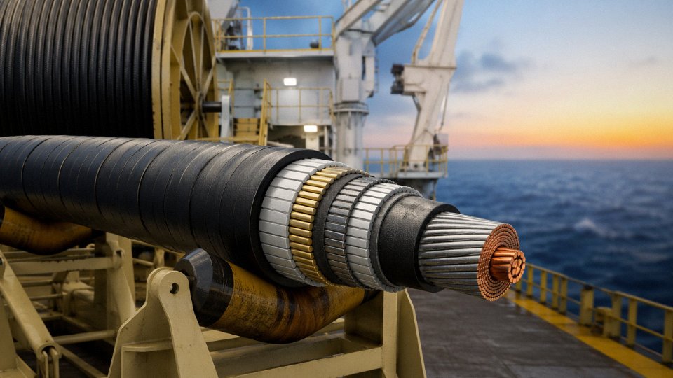
Consider a 3-phase motor feeder for a 200 kW pump motor on an offshore petrochemical platform, fed from a 6.6 kV switchboard. Going field by field: the installation method is cable tray on an open deck — immediate UV, salt spray, and occasional hydrocarbon splash exposure. System voltage is 6/10 kV (Uo/U), 60 Hz. Full-load current at 6.6 kV for a 200 kW motor runs roughly 22–26 A depending on power factor and efficiency, but derating for 45°C ambient deck temperature and grouping with adjacent feeders could reduce the allowable current by 15–25%, so the cross-section calculation needs to reflect that corrected figure, not the base table value.
For conductor: copper, 3-core, 25–35 mm² depending on the corrected current and the voltage drop along the run length. Insulation: EPR at 90°C — EPR handles the thermal cycling and occasional ozone exposure better than XLPE in marine environments, and it stays flexible in cold weather layups during maintenance. Sheathing: an inner bedding, SWA for mechanical protection against deck traffic and dropped tools, then an outer sheath in a mud-resistant, flame-retardant compound — here, a low-smoke zero-halogen outer sheath is typically specified because an offshore platform fire event with halogen-generating smoke in enclosed corridors is a survivability issue, not just a code compliance checkbox.
Standards: IEC 60092-353 for offshore shipboard cable, supplemented by the platform owner’s engineering specification (most offshore operators have one). Environmental fields: operating temperature −20°C to +70°C ambient, UV Class 1, H₂S resistance required, continuous seawater splash category.
A generic industrial catalog cable — even one correctly rated at 6/10 kV — would likely have failed on the LSZH sheath, the EPR insulation, and the offshore standard certification. That’s not a minor oversight.
Common Errors That Cause Field Failures
Specifying voltage rating without considering transient overvoltages is probably the most common. Variable frequency drives and capacitor bank switching generate transients that can exceed rated insulation voltage repeatedly before anyone notices — until partial discharge damage accumulates and you get a fault.
Ordering by conductor cross-section without stating insulation class means a supplier filling the order to minimum standard might ship 70°C PVC where 90°C XLPE was needed. Both cables can be, say, 50 mm² copper 3-core. They are not the same cable.
Omitting armoring type when the route crosses a road crossing is another one. “Armored cable” does not specify whether it’s SWA, AWA, or double-tape, and these have meaningfully different crush resistance ratings.
Failing to specify minimum bend radius in cable tray or J-hook installations leads to installers bending large-section cables tighter than the insulation system tolerates, causing micro-cracking that won’t show up on a commissioning megger test but will degrade over 3–5 years of thermal cycling.
Using a Manufacturer’s Datasheet Properly
A datasheet for a well-documented cable contains at minimum: a construction table, current rating tables at multiple ambient conditions, correction factor tables for grouping and burial depth, and mechanical property tables (minimum bend radius, tensile strength, short-circuit current rating). The mistake is picking a number from the current rating table and ignoring the rest.
Cross-reference all four tables together. The current rating table gives a ceiling under standard conditions. The correction factor tables tell you how far below that ceiling your actual installation sits. The mechanical property table tells you whether your installation geometry is even permissible. Used in isolation, any single table can produce a specification that looks right on paper and fails in service.
Engineering Partnership, Not Catalog Ordering
Jinda’s technical support team regularly reviews incoming cable schedules — full project cable lists, not single line items — checks each specification against the declared installation conditions, flags mismatches before production, and proposes alternatives where a different construction can meet the same performance requirement at lower cost or shorter lead time. That kind of review catches the errors described above before they become site problems.
If you have a cable schedule ready, or even a preliminary one, submit it for a free technical review. The earlier in the project that happens, the more options remain open.
Cable specifications that omit derating conditions, armoring type, and environmental parameters routinely result in field failures within the first operational cycle.True
Incomplete specifications cause suppliers to default to minimum-standard construction; the resulting cables may pass initial commissioning tests but fail under actual load, environmental, and mechanical conditions within months to a few years, consistent with documented failure analysis patterns in industrial electrical maintenance.