Miswire a power cable — swap neutral and ground, or get the hot conductor wrong — and the consequences move fast. Equipment trips on first energization, or worse, it runs with the chassis sitting at line voltage and nobody notices until someone touches it. In a production environment, that second scenario is the one that causes injuries and triggers regulatory shutdowns. Replacement of damaged drives, motors, or switchgear after a wiring fault typically runs anywhere from a few hundred dollars for a small VFD to tens of thousands for a medium-voltage transformer, depending on what absorbs the fault energy first.
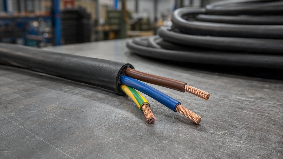
A standard power cable contains three wires: a live (hot) conductor that carries current from the source at 120 V in North America or 230 V in most of Europe and Asia, a neutral conductor that completes the circuit and sits near 0 V under balanced load, and a ground (earth) conductor that normally carries no current at all — its sole job is to provide a safe fault-current path back to the source to trip the overcurrent device before a fault becomes a fire or a shock.
What makes this deceptively simple to state but genuinely consequential in practice is that the three wires look similar, their color codes change depending on which country manufactured the cable, which country the installation is in, and how old the wiring is — and the penalties for confusing them are not symmetrical. Getting it wrong in one direction gives you a nuisance trip. Getting it wrong in another direction gives you an energized enclosure.
Wire 1 — The Live (Hot/Phase) Conductor: Voltage Carrier, Current Source, and Sizing Criteria
The live conductor is the wire doing the primary electrical work. It carries the voltage potential from the transformer secondary or generator output terminal all the way to the load — motor, heater, control panel, whatever is on the receiving end — and maintains the potential difference that forces current through the circuit. Without it, nothing moves. Every other conductor in the cable is essentially there to manage what happens to that energy once it arrives.
Electrical Role and Why It Matters to Get This Right
In a standard single-phase circuit, the live conductor operates at 120 V (North America) or 230 V (Europe and most of Asia) relative to neutral under normal conditions. In three-phase industrial installations, each phase conductor sits at roughly 400 V line-to-line (230 V line-to-neutral in a 400/230 V system), which is the everyday reality on most factory floors outside North America. That sustained voltage potential means the live conductor’s insulation is doing continuous electrical work, not just fault protection — a distinction that matters when you’re specifying cable for a 20-year service life rather than a three-year equipment lease.
Conductor Material: Copper vs. Aluminum
Annealed copper remains the default for most industrial and commercial wiring. Conductivity runs around 58 MS/m, it’s easy to terminate, and it tolerates vibration reasonably well — relevant if you’re running cable to a compressor or a press. Aluminum comes in at roughly 35 MS/m, so you need a larger cross-section to carry the same current: a 16 mm² aluminum conductor is approximately equivalent to a 10 mm² copper in ampacity terms, give or take installation method and ambient temperature. Aluminum’s weight advantage (about one-third the density of copper) makes it genuinely attractive for overhead distribution feeders and large-cross-section building service entrances above 35 mm² or so, where the mass savings are meaningful. For branch circuits, panel feeders in tight conduit, or anything that gets terminated repeatedly by maintenance staff, copper is easier to live with.
Insulation Requirements and Material Trade-offs
IEC 60227 and UL 83 both specify minimum insulation wall thickness based on voltage class. For a 300/500 V rated cable with a 2.5 mm² conductor, IEC 60227 requires roughly 0.6–0.7 mm of PVC insulation; step up to the 450/750 V class and you’re looking at 0.8–1.0 mm, depending on conductor size. These aren’t large margins — the standards are designed around normal service, not abuse.
PVC insulation is rated to 70°C continuous conductor temperature. That ceiling becomes a real constraint in high-ambient environments: an engine room running at 45°C ambient leaves you very little thermal headroom. XLPE (cross-linked polyethylene) pushes the continuous rating to 90°C and handles short-circuit thermal stress better. It also ages more gracefully — XLPE typically outperforms PVC by 10–15 years in service life under similar loading conditions, though the cable will cost more upfront. For drives, furnace wiring, or any installation where the cable is near heat sources, the premium is usually worth it.
A 2.5 mm² copper conductor rated in free air carries approximately 23 A under IEC 60364-5-52 reference conditions.True
IEC 60364-5-52 Table B.52.2 lists 23 A for a 2.5 mm² copper conductor in free air (installation method B2, PVC insulation, 30°C ambient). This figure drops — sometimes to 16–18 A — when the cable is bundled or run in conduit with other cables.
A 10 mm² copper conductor steps up to roughly 52–57 A in free air under the same standard. These numbers shift meaningfully with installation method, grouping, and ambient temperature, so treat the base table values as a starting point, not a final answer.
Voltage Drop: Why Ampacity Alone Isn’t Enough
Passing the ampacity check doesn’t mean the cable is correctly sized. On runs longer than 30 m — common in warehouse distribution, outdoor lighting circuits, or any sprawling plant layout — voltage drop can become the governing criterion. IEC recommends keeping drop below 4% for final circuits (some national annexes allow 5% to the origin of the final circuit). In practice, a 2.5 mm² copper circuit running 50 m at 16 A will eat most of that budget, which is why you often see 4 mm² or even 6 mm² cable specified on longer runs even when the load is modest. Oversizing the live conductor for voltage drop rather than pure ampacity is a routine engineering decision, not an exception.
How Jinda Engineers the Live Conductor
At Jinda’s production facilities, the process starts with oxygen-free copper rod — typically 8 mm diameter — drawn down through progressive dies to the target wire diameter. Stranding follows IEC 60228: Class 1 for solid conductors used in fixed installations, Class 2 for standard stranded, Class 5 for flexible cables (portable tools, machinery), and Class 6 for ultra-flexible applications like welding leads or robotic cable tracks. Tighter strand lay and finer wire diameter in Class 5 and 6 cables aren’t just about flexibility — they also improve fatigue resistance in applications with continuous bending cycles. Insulation is applied by continuous extrusion, which gives consistent wall thickness around the conductor geometry; uneven walls create local field concentration points that degrade insulation life faster than the rated temperature would suggest. Quality control includes spark testing at voltages well above the rated class to catch any pinholes before the cable leaves the line.
Wire 2 — The Neutral Conductor: Return Path, Balance Point, and the Consequences of Getting It Wrong
The neutral wire is the one most installers treat as an afterthought. It doesn’t spark when you touch it under normal conditions, it’s rarely the one that trips a breaker, and in a single-phase residential circuit running a resistive load, it really does sit close to 0 V. That combination of behaviors breeds a dangerous familiarity. On the industrial plant floor, neutral problems are subtle right up until they aren’t — and when they surface, the consequences range from nuisance tripping to equipment destruction to shock fatalities.
The Basic Function: Completing the Circuit Loop
At its core, the neutral conductor provides the return path for current that has flowed through the load. Without it, the circuit cannot close, and no useful work gets done. In a 230 V single-phase supply, the live conductor drives current through the load; the neutral returns that current back to the distribution transformer’s center tap or star point, which is itself bonded to earth at the supply end. The voltage reference function matters equally — the neutral establishes the “zero” against which line voltage is measured, which is why instrumentation and control circuits depend on a solid, low-impedance neutral as much as on a clean live feed.
Why Neutral Is Not at Zero Volts Under All Conditions
The neutral conductor always sits at 0 V relative to ground.False
In three-phase four-wire systems, load imbalance causes current to flow through the neutral conductor's impedance, raising its potential above true earth ground. Even modest imbalances — 10 A of unbalanced current through a neutral with 0.05 Ω impedance — produce 0.5 V of neutral-to-ground offset. With longer cable runs or higher impedance neutrals, that offset rises proportionally and can interfere with sensitive control electronics or trip earth leakage devices.
A 10 A imbalance through a neutral conductor with roughly 0.05 Ω impedance (realistic for a medium-length run of 4 mm² conductor) produces around 0.5 V neutral-to-ground. That sounds trivial. In a 24 V DC control circuit referenced to that same neutral, 0.5 V is a measurable fraction of the signal level — enough to cause spurious triggering in older PLC input cards. In a poorly designed industrial panel I’ve seen audited, neutral-to-ground voltage of 3–4 V (a longer run, undersized neutral, heavy imbalance on one phase) was causing intermittent faults that took weeks to trace because nobody thought to check the neutral first.
The Open Neutral: The Scenario That Actually Kills People
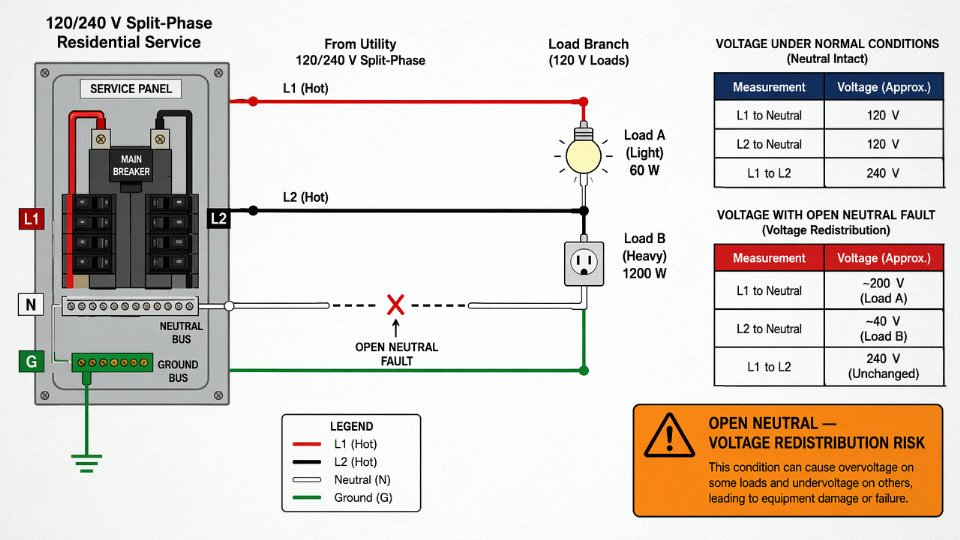
The myth that neutral is “safe to handle” because it’s near ground potential collapses completely the moment neutral continuity is lost. An open neutral in a 120/240 V split-phase system causes the two legs to redistribute voltage across whatever loads remain connected — a light load on one leg and a heavy load on the other will see the heavy-load side drop while the light-load side rises, potentially toward the full 240 V. Equipment chassis connected to that circuit through a hot-neutral reversal or an improperly wired outlet can rise to full line potential relative to true earth. This is not a theoretical edge case; it shows up in older wiring, corroded neutral terminals at service panels, and loose neutral connections at distribution boards — the kind of connection that reads fine with a cold meter probe and fails intermittently under thermal expansion at load.
Neutral Sizing: The Rules Change With Load Type
In a straightforward balanced single-phase circuit, the neutral carries exactly the same current as the live, so it’s sized identically — same cross-section, same conductor material. That’s the simple case.
Three-phase four-wire systems complicate things considerably. Under perfectly balanced linear loads, neutral current theoretically cancels to zero. In practice, balanced loads don’t exist outside textbooks, and more critically, modern industrial and commercial loads are almost never linear. Variable frequency drives, switch-mode power supplies, LED drivers, UPS systems — all of these generate third-harmonic current (and its multiples: 9th, 15th harmonic). Unlike fundamental-frequency current, third-harmonic components from all three phases add together in the neutral rather than canceling. In a heavily nonlinear installation, neutral current can reach 1.73× the phase current, which means a neutral sized to match the phase conductor is thermally overloaded even when no individual phase is overloaded. The cable looks fine on a clamp meter at the phase; the neutral is quietly cooking inside the bundle.
For data centers, automation panels, and any environment with significant VFD loading, the correct approach is to specify a neutral conductor sized at 150–173% of the phase conductor cross-section, or to use cables specifically engineered with an oversized neutral. Jinda’s harmonics-tolerant cable range for industrial automation and data center applications addresses exactly this — the neutral conductor cross-section is scaled to the expected harmonic load profile, not simply matched to the phase, and the insulation system is rated for the additional thermal stress that continuous harmonic current imposes on the bundle.
Color Coding Is a Safety System, Not Decoration
IEC 60446 specifies blue for neutral; NEC calls for white or gray. Older UK installations used black for neutral (which is now live brown in current IEC practice — a genuine source of confusion during any retrofit). Maintaining color discipline isn’t about aesthetics. A maintenance electrician working on a multi-cable termination at 2 AM during a breakdown is going to trust color before pulling out a meter. If neutral and live insulation colors have been mixed — whether through sloppy original installation, field repairs with whatever sleeving was available, or cable repurposing — the risk of a live-neutral reversal or an unsafe working assumption is real and repeatable. Verify with a meter regardless, but don’t create environments where the meter becomes the only safeguard.
Wire 3 — The Protective Earth (Ground) Conductor: Fault Clearing Mechanism, Touch Voltage Limits, and Grounding System Types
The ground wire is the one conductor in the cable that — under normal operating conditions — carries no current at all. That makes it easy to underestimate. It’s also the conductor most likely to save someone’s life when everything else goes wrong.
What the Ground Conductor Actually Does
Its job is straightforward in principle: bond every exposed metal surface of a piece of equipment to true earth potential. When a live conductor develops a fault and contacts a metal enclosure — a motor frame, a control cabinet door, a pump housing — the ground wire gives that fault current a low-impedance return path back to the source. Current rushes through the PE conductor, not through the next technician who touches the enclosure. The overcurrent device sees a large fault current and trips. The hazard is cleared in milliseconds if the system is designed correctly.
Remove the ground wire, or let its connection corrode to a high resistance, and you lose that mechanism entirely.
The Fault Clearing Loop and Why Impedance Is Everything
IEC 60364-4-41 sets a hard requirement: for circuits up to 32A, the protective device must clear the fault within 0.4 seconds. For socket outlet circuits, the requirement tightens to 0.2 seconds in some configurations. Whether that happens depends almost entirely on the impedance of the fault loop.
The arithmetic is basic Ohm’s law, but the implications are real. Say you have a 230V TN-S circuit protected by a 16A Type B MCB. That breaker requires roughly 5× its rated current — around 80A — to trip within the magnetic (instantaneous) range, which is what actually clears a fault in under 0.4 s. If your fault loop impedance is 230 ÷ 80 = 2.875 Ω or less, you’re fine. Creep above that — through corroded terminations, an undersized PE conductor on a long run, or a broken earth connection at a junction box — and fault current drops below the instantaneous trip threshold. The breaker may still eventually trip on the thermal element, but that can take seconds or longer. Long enough for a person to complete that circuit instead.
Touch Voltage: The Number That Matters Most
IEC 60479 puts the conventional safe AC touch voltage limit at 50V. That threshold exists because above it, ventricular fibrillation becomes a credible outcome depending on current path, body resistance, and contact duration.
A high-impedance ground path doesn’t necessarily trip the breaker — it just limits fault current. But voltage divides across the impedance, and a significant portion of 230V can sit on an enclosure chassis indefinitely without tripping anything. A 115V enclosure-to-floor potential is not unusual in a degraded TT installation with poor local earth resistance. The circuit functions normally. The equipment runs. Nobody knows until someone leans on the machine.
TN-S, TN-C, and TT: Three Systems, Three Cable Requirements
These IEC grounding arrangements directly affect how you specify the cable.
| System | PE/N arrangement | Typical cable construction | Key risk if misapplied |
|---|---|---|---|
| TN-S | Separate PE and N throughout | 3-core + separate PE (5-wire for 3-phase) | Confusion of PE and N terminals during install |
| TN-C | Combined PEN conductor | 4-wire 3-phase (PEN carries both functions) | PEN open circuit — entire system floats to phase voltage |
| TT | Local earth electrode, no metallic return to source | Standard 3-core; earth quality depends on electrode resistance | High fault loop impedance; RCD mandatory, not optional |
TN-C is worth a specific caution. The PEN conductor must never be switched or fused — doing so can lift neutral and earth simultaneously, putting phase voltage on every earthed surface in the installation. In practice, TN-C has largely been phased out of new construction in most European markets, but it persists in older industrial plants and in parts of Eastern Europe and Asia. If you’re working in a facility built before the 1990s, verify the system type before assuming TN-S.
Identifying the Ground Conductor — and Why That Identification Is Not Decorative
IEC 60446 mandates the green-yellow bicolor stripe for PE conductors and prohibits that color combination from being used for any other function. This is not a convention. Using green-yellow on a neutral or phase conductor in an IEC installation is a code violation that creates a genuine maintenance hazard — a technician isolating what they believe is an earthed conductor may actually be holding a live one.
North American NEC installations use either bare copper or green insulated wire for the equipment ground. Bare copper is common in metallic conduit runs and in most North American building wire configurations. The visual identification principle is the same: a maintainer working on a de-energized circuit at 2 a.m. under a deadline should not have to reason through wire identity.
Sizing: Don’t Undersize PE on Long Runs
IEC 60364-5-54 sets minimum PE cross-sections: for phase conductors up to 16 mm², the PE must match the phase conductor area. For phase conductors between 16 mm² and 35 mm², a 16 mm² copper PE is the minimum. Above 35 mm², the PE must be at least half the phase conductor area.
Those are minimums for short runs. On a long cable run — say, 80–120 m feeding a 22 kW motor — the PE conductor’s resistance adds directly to the fault loop impedance. In practice, upsizing the PE by one or two cross-section steps on runs over roughly 50–60 m is often cheaper than the engineering investigation that follows an unexplained nuisance trip or, worse, a near-miss. The cable cost difference between a 10 mm² and 16 mm² PE is marginal over the equipment life. The consequences of marginal fault current in a heavily loaded industrial environment are not.
IEC 60364-4-41 requires protective devices to clear faults within 0.4 seconds on circuits up to 32A.True
IEC 60364-4-41 (Protection against electric shock — Automatic disconnection of supply) specifies maximum disconnection times of 0.4 seconds for final circuits not exceeding 32A in TN systems at 230V, ensuring fault energy is interrupted before it reaches a dangerous threshold.
Global Color Code Standards Compared: IEC 60446, NEC, AS/NZS 3000, and Legacy Wiring — A Procurement and Installation Reference
Color coding is one of those things that feels like a minor detail until someone gets it wrong. At that point it stops being a wiring convention and becomes an incident report.
The Five Major Standards Side by Side
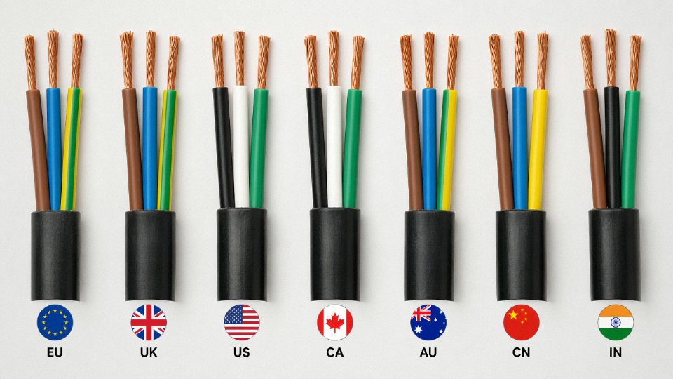
| Standard | Region | Live / Phase | Neutral | Protective Earth |
|---|---|---|---|---|
| IEC 60446 (current) | International / EU | Brown | Blue | Green-Yellow stripe |
| NEC / NFPA 70 | USA, Canada | Black (or Red/Blue for multi-wire) | White or Grey | Bare copper or Green |
| AS/NZS 3000 (2018) | Australia, New Zealand | Brown (active) | Blue | Green-Yellow stripe |
| SANS 10142 | South Africa | Red | Black | Green-Yellow stripe |
| Pre-2004 UK legacy | UK (obsolete) | Red | Black | Green |
Three-phase cabling under IEC 60446 adds L1/L2/L3 as brown, black, and grey respectively. That creates an immediate ambiguity: a black conductor is a live phase wire in IEC three-phase systems, a hot conductor in NEC installations, and the neutral in SANS 10142. Grey is neutral in some NEC applications. If your procurement team is pulling cables from multiple sources across a single project without explicit function labeling, you are building in a future fault.
The Blue Wire Problem — Why This Has Killed People
The single most dangerous color collision involves blue. Under current IEC 60446, blue is neutral. In pre-2004 UK wiring — still present in millions of buildings — black was neutral and blue was used in switched-live applications, flex leads, and some three-phase configurations as a live conductor. A maintenance electrician working on a mixed-vintage UK installation, or a newly trained technician who learned IEC conventions, can reasonably assume a blue wire is safe to handle. In legacy UK contexts, it may not be.
Wire color coding errors during maintenance have caused fatal electrocutions in mixed-standard installationsTrue
Electrical safety regulators in the UK and Australia have documented fatalities and serious injuries attributed to misidentification of wire functions in installations where legacy and current color standards coexisted, particularly during refurbishment work. This is one reason IEC 60446:2007 and the UK's BS 7671:2008 required transition labeling at all new terminations in existing installations.
The practical rule on any refurbishment or extension project: test every conductor for live voltage before touching it, regardless of color. Treat color as a starting hypothesis, not a guarantee.
Re-Identification Sleeving — What the Standards Actually Allow
Both IEC and NEC permit re-sleeving conductors to bring them into compliance with current color conventions, but only at termination points. You cannot sleeve a conductor mid-run as a substitute for using correctly colored cable from the start. Under NEC 200.6, white or grey conductors repurposed as ungrounded (hot) conductors must be permanently re-identified with tape, paint, or sleeving at each visible point. IEC practice is similar — BS 7671 requires a permanent sleeve or label at every accessible termination in mixed-vintage work.
In practice, sleeving at junction boxes, distribution boards, and equipment terminals is workable. Relying on it across a large installation as a cost-saving alternative to specifying the right cable upfront is a maintenance liability. Future technicians will not always find or trust the sleeves.
How to Specify Correctly Across Borders
For any international project or multi-source procurement, specify both the applicable color standard and the conductor function explicitly in the purchase order. A line item that reads only “3-core 2.5 mm² cable, blue/brown/green-yellow” will get you IEC-compliant colors — but if your site operates under SANS 10142 or NEC, the installed cable will be non-compliant the moment it hits the termination board.
Jinda produces region-specific variants to address exactly this: standard IEC 60446 color runs, UL-listed NEC-compliant cables with black/white/green insulation, AS/NZS 3000-compliant active/neutral/earth configurations, and custom color-coded harness cable for OEM equipment manufacturers who specify branded wire assemblies. For bulk procurement contracts spanning multiple destination countries, specifying color standard by IEC or NEC designation rather than by color name alone prevents substitution errors when manufacturing runs overlap or when a partial order ships from a different production batch.
A Note on Single-Phase vs. Three-Phase Confusion
A surprisingly common specification error: ordering “3-wire cable” without clarifying whether you need single-phase three-wire (live, neutral, PE) or three-phase three-wire (L1, L2, L3 — no neutral). They are both three-conductor cables. Under IEC, the three-phase version uses brown, black, and grey — all of which are live. Receiving one when you needed the other is not just an inconvenience; in a three-phase-only cable there is no neutral reference, and connecting equipment designed for single-phase supply will likely destroy it. Always state the system configuration — single-phase or three-phase, with or without neutral — alongside the color standard in the specification.
How Three-Wire Cables Are Manufactured: From Copper Rod to Finished Cable — Jinda’s Production Process
Understanding what the three conductors do electrically is one thing. Knowing how they’re actually built — and where manufacturing decisions directly affect the safety performance you’re relying on — is something else entirely. The two are more connected than most procurement specs acknowledge.
Copper Rod Drawing: Where Conductivity Is Decided
Everything starts with 8 mm electrolytic copper rod, typically sourced to a purity of 99.9% Cu or better. That rod gets pulled through a series of progressive tungsten carbide dies — sometimes 12 to 20 passes depending on target diameter — with each die reducing the cross-section by roughly 15–25%. Drawing speed matters here more than people realize. Too fast and you generate heat that work-hardens the copper, raising resistivity and making the wire brittle. Too slow and you’re bleeding productivity for no benefit.
After drawing, the wire goes through an annealing furnace. For IEC 60228 Class 5 (fine stranded, flexible) conductors, annealing temperature typically runs between 350–500°C depending on wire diameter and line speed — the goal is to restore elongation to ≥15–20% while keeping resistivity at or below 0.01724 Ω·mm²/m. Class 2 (solid or standard stranded) tolerates a bit less precision here, but you still can’t skip it. Conductors that skip proper annealing tend to fail fatigue tests and will crack at terminations during installation. That’s a field problem that traces straight back to the drawing line.
Stranding and Bunching: Building in Flexibility Without Sacrificing Uniformity
Individual drawn wires are twisted together in defined lay lengths — shorter lay for higher flexibility (Class 5/6 fine stranded), longer lay for fixed-installation Class 2 constructions. Jinda runs computer-controlled planetary stranding machines that hold lay ratio tolerances tightly, which matters because inconsistent lay length produces non-uniform current distribution along the conductor length. In high-current applications, that unevenness shows up as localized heating. It’s subtle, but over years of service it contributes to premature insulation degradation.
Insulation Extrusion: The Layer That Makes Each Conductor Independent
Each stranded conductor gets its insulation applied in a crosshead extruder. PVC compounds run at melt temperatures of roughly 160–200°C; XLPE requires 180–220°C with a higher-pressure die to achieve proper cross-linking in the vulcanization tube downstream. LSZH compounds are fussier — they’re more sensitive to moisture contamination in the feed hopper and to screw speed variation, and they’ll show surface roughness or voids if the extruder temperature profile isn’t dialed in correctly.
Wall thickness uniformity is held to ±0.1 mm in Jinda’s process. That tolerance isn’t arbitrary — it’s what maintains consistent dielectric strength around the full conductor circumference. A thin spot of 0.2 mm on a 230 V rated insulation wall doesn’t fail immediately, but it creates the location where voltage stress concentrates over time.
Jinda controls insulation wall thickness to ±0.1 mm tolerance during extrusion, ensuring consistent dielectric strength across each conductor.True
This tolerance is achievable with modern servo-controlled crosshead extruders and inline eccentricity gauges, and is consistent with standard industrial cable manufacturing practice for maintaining dielectric performance per IEC 60227 and IEC 60502 requirements.
Core Laying-Up: Assembling the Three Conductors
The three insulated cores — live, neutral, and ground — are twisted together in the cabling machine at a defined lay length, typically 8–15× the finished cable diameter depending on flexibility class. Tighter lay improves roundness and crush resistance; longer lay reduces bending stiffness slightly. Fillers (usually PP or jute compound) are introduced to fill interstitial gaps, keeping the assembled bundle as circular as possible. A non-circular cable causes real headaches during conduit pulls — it jams.
Sheathing and Final Jacketing
The outer jacket — PVC, polyurethane (PUR), or LSZH depending on end-use environment — goes on in a second extruder pass over the laid-up cores. Shore A hardness for the finished sheath typically runs 60–80 for flexible cables; harder compounds are used in fixed-installation or direct-burial applications. PUR jackets push toward the harder end and are worth specifying for anything seeing oil or continuous flexing. Standard PVC is fine for static indoor runs.
Quality Control Checkpoints That Connect Manufacturing to Electrical Safety
Finished cable doesn’t leave without spark testing at 6 kV across each insulated core — this catches pinholes and thin spots that dimensional gauging alone misses. Conductor resistance is measured per IEC 60227 and compared against Class 2 or Class 5 limits. Dimensional checks confirm sheath thickness and overall diameter. For LSZH constructions, fire performance testing to IEC 60332-1 or IEC 60332-3 (depending on bundle installation) confirms that the flame propagation behavior the spec promised is actually what the finished cable delivers.
Each of these steps feeds directly back to the three-conductor electrical design. A ground conductor that’s under-annealed may resist fault current differently than specified. An insulation wall with poor eccentricity control undermines the voltage isolation between live and neutral that the whole system depends on. Manufacturing discipline and electrical safety aren’t separate topics — they’re the same topic.
Selecting the Right Three-Wire Power Cable for Your Application: Key Specification Parameters and Common Mistakes
Specifying a three-wire power cable looks straightforward until something goes wrong — a motor running hot because of undervoltage, a drag-chain cable failing after three months, or an RCD tripping intermittently on a VFD panel with no obvious fault. Most of those problems trace back to a specification written too quickly, usually by someone who stopped at ampacity and called it done.
Here is the selection sequence that actually holds up in practice.
Work Through Voltage Rating First, Before Anything Else
Voltage class drives insulation wall thickness, material grade, and ultimately cost. The three tiers you will encounter on most international projects are 300/500V (light flexible cords, control cables, most household appliance leads), 450/750V (general industrial fixed wiring, switchboard wiring), and 0.6/1kV (heavy industrial feeders, motor supply cables, most outdoor infrastructure work). Picking 300/500V for a run that terminates at a 690V motor feeder is not a small mistake — it is a latent arc fault waiting for a bad day. When in doubt, step up one voltage class. The cost difference is usually 5–15% on the cable unit price, negligible against the cost of a rewire.
Conductor Cross-Section: Ampacity Is Necessary but Not Sufficient
This is where the most common and costly mistake happens. Engineers pull an ampacity table, confirm that 2.5 mm² copper handles 16A comfortably, and stop there.
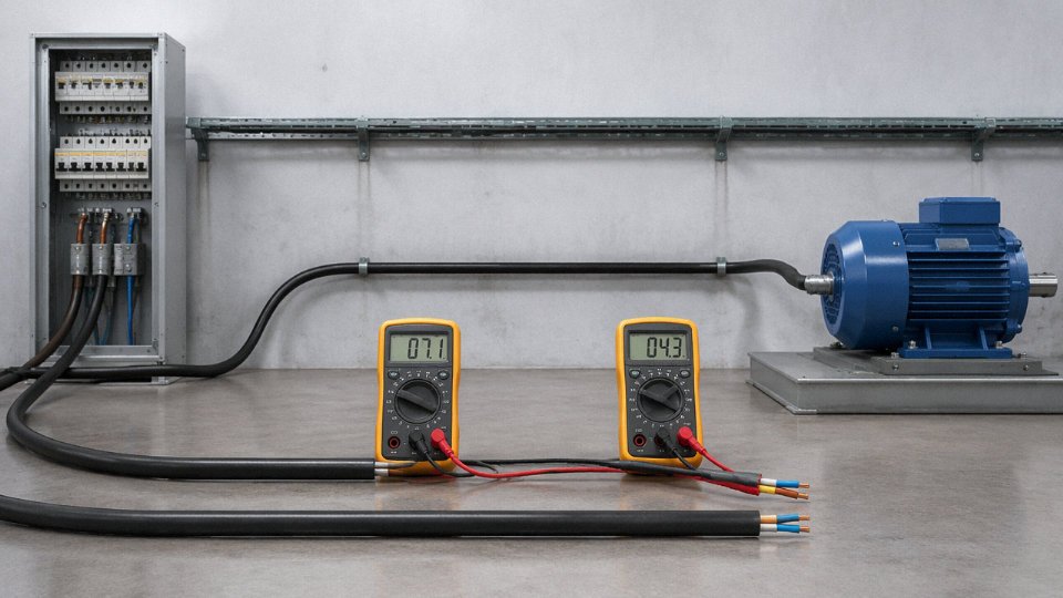
Consider a 16A circuit feeding a small packaging machine 45 m from the distribution board. At 230V single-phase, the voltage drop formula gives roughly: V_drop = (2 × ρ × L × I) / A, where ρ for copper is approximately 0.0175 Ω·mm²/m. Plugging in: (2 × 0.0175 × 45 × 16) / 2.5 ≈ 10.1V. That is 4.4% of 230V — over the 4% limit set by IEC 60364-5-52 and most national codes for final circuits. The machine runs, but it runs at reduced voltage, the motor runs warm, and the warranty argument with the machine supplier is unpleasant. Upgrading to 4 mm² drops that figure to roughly 2.7%, comfortably within limits, and the cost difference on a 45 m run is typically under $12–20 depending on copper pricing. Do the voltage drop calculation. Every time.
Insulation and Jacket Material: Match the Environment, Not the Catalog Default
PVC is fine for dry indoor fixed installations — it is cost-effective and well understood. Push the ambient above roughly 70°C continuous and you need XLPE, which maintains its mechanical and dielectric properties up to 90°C rated conductor temperature. Outdoor UV exposure without conduit protection calls for either UV-stabilized PVC compound or a polyethylene outer sheath. Chemical environments — battery rooms, paint shops, food processing floors with cleaning agents — usually require PUR (polyurethane) jacket, which resists both oils and the repeated flexing that mechanical handling equipment imposes. PUR is essentially mandatory for crane pendant cables, robotic arm cabling, and drag-chain applications where standard PVC sheaths crack within months.
For public buildings, tunnels, underground stations, and offshore platforms, LSZH (Low Smoke Zero Halogen) compound is not optional — IEC 60332-3 and most building codes in those environments mandate it. The reason is practical: in a fire, a PVC-jacketed cable generates hydrogen chloride gas, which is toxic and corrosive to electronics. LSZH cables produce significantly less smoke and no halogenated acid gases.
Flexibility Class: Fixed Wiring and Moving Cables Are Not the Same Product
IEC 60228 defines flexibility classes 1 through 6. Class 1 and 2 are solid or stranded conductors for fixed installation — smaller surface area per conductor, lower cost, not designed to flex repeatedly. Class 5 and 6 use fine-wire stranding specifically for flexible cords and moving applications. Installing a Class 2 cable in a drag chain that cycles hundreds of times per day will cause conductor fatigue fractures, usually at a termination point, within a year or two. The failure mode is resistive heating at the break, which is hard to diagnose and occasionally starts fires.
Standard and Certification: Know Your End Market
IEC 60227/60245 covers most international industrial markets. UL 44 and UL 62 govern the North American market, and CSA C22.2 covers Canada specifically. AS/NZS 3191 applies to Australia and New Zealand flexible cords. Exporting to multiple markets or supplying OEM equipment that ships globally sometimes requires dual-listed cables — more expensive but avoids hold-ups at customs or failed third-party inspection. Confirm the required mark before you write the RFQ.
The VFD Ground Conductor Trap
Variable frequency drives generate high-frequency leakage currents on the ground conductor — in the range of a few kilohertz depending on switching frequency and cable capacitance. Standard sizing tables do not account for this. The result is nuisance RCD tripping on otherwise sound circuits, or in worse cases, thermal stress on an undersized ground conductor over time. For VFD applications, specify screened or shielded cable variants and consult the cable manufacturer about ground conductor sizing beyond the standard 50% minimum rule. This is one of those details that disappears in a generic catalog spec sheet.
A 2.5 mm² copper conductor meets IEC 60364 ampacity for a 16A circuit but may fail the 4% voltage drop limit at run lengths above roughly 40 m at 230V.True
Voltage drop calculation using copper resistivity (≈0.0175 Ω·mm²/m) for a 16A single-phase load over 40–45 m in 2.5 mm² cable yields approximately 4–4.5% drop, exceeding the IEC 60364-5-52 recommended 4% limit for final circuits.
RFQ Checklist for Cable Manufacturers
When submitting an enquiry, include every one of these items or expect the quote to come back with assumptions that may not match your project:
- Conductor material (copper or aluminum) and purity/standard
- Conductor cross-section in mm²
- Number of cores (confirm three-wire, not two or four)
- Voltage class (e.g., 0.6/1kV)
- Insulation type (PVC, XLPE, LSZH, rubber)
- Outer sheath/jacket type (PVC, PUR, LSZH, PE)
- Flexibility class per IEC 60228
- Color code standard (IEC 60446, NEC, or project-specific)
- Required certification or listing mark
- Quantity in meters or reel configuration
- Delivery schedule and packaging requirement (drums, coils, cut lengths)
Missing even two or three of these items typically adds a round of back-and-forth that delays lead times by one to two weeks, and sometimes results in a cable that technically meets the spec written but not the application intended.
Jinda’s technical support team routinely works through this checklist with procurement managers and project engineers before orders are placed — running conductor sizing calculations, recommending insulation compounds for specific chemical exposure data sheets customers provide, and shipping samples for in-house qualification testing before bulk order commitment. For unusual environments or non-standard certifications, that kind of early-stage engagement tends to be worth the time.
Three-Wire Cable Installation Best Practices: Termination, Testing, and the Most Dangerous Wiring Errors to Avoid
Good cable specification means nothing if the installation undoes it. A significant share of field failures I’ve seen trace back not to manufacturing defects but to termination shortcuts, skipped tests, or one conductor connected in the wrong order. The cable was fine. The installation wasn’t.
Termination: Strip Length, Ferrules, and Torque
Strip only enough insulation to seat the conductor fully in the terminal — no more. Leaving excess bare conductor exposed invites phase-to-phase or phase-to-ground contact inside enclosures, especially once vibration and thermal cycling loosen things over time. For most screw terminals, 8–12 mm of stripped length is typical; the terminal manufacturer’s datasheet will tell you exactly, and it’s worth checking rather than eyeballing it.
On stranded conductors, always fit wire-end ferrules (end sleeves) before inserting into a screw terminal. Without them, individual strands spread under clamping force, some escape the terminal jaw entirely, and you end up with both increased contact resistance and a genuine short-circuit risk from rogue strands touching adjacent conductors. For 2.5 mm² terminals, IEC 60999 specifies tightening torque in roughly the 0.5–0.8 Nm range — exact value depends on terminal design and conductor material. Undertorquing causes resistive heating at the joint; overtorquing can fracture the conductor or crack the ferrule, which creates a latent fault that only shows up later under load.
Ground First, Ground Last — Always
Connect the protective earth conductor before either current-carrying conductor, and disconnect it after both others are isolated. This isn’t ceremonial. During the brief window when a live conductor is connected but the ground isn’t, any fault makes the enclosure live with no clearing path. During disconnection under maintenance, the reverse logic applies — the ground must be the last thing to come off, maintaining fault protection until the circuit is truly dead. This sequence is non-negotiable in any environment where personnel are working near live equipment.
The Three Wiring Errors That Cause Real Harm
Reversed live and neutral is more common than it should be, particularly on sites using older equipment without keyed connectors. The downstream effect is that the neutral rail sits at line voltage — equipment appears to power off when switched, but internal components remain energized. More critically, in some RCD configurations, a live-neutral reversal means the device won’t trip on a fault the way it was designed to. People get hurt this way.
An open ground — ground wire present in the cable but not terminated at one or both ends — eliminates the entire fault-clearing mechanism while giving the installation the visual appearance of being complete. Touch voltage builds on metalwork silently until a fault occurs. This is arguably the most dangerous error because it’s invisible in normal operation.
Shared neutrals between separate circuits create two problems simultaneously: neutral conductor overload (in 3-phase systems with non-linear loads, harmonic currents can cause the shared neutral to carry more current than any phase conductor), and interference between circuits that manifests as equipment malfunction or nuisance tripping. Keep neutrals dedicated to their circuits.
Reversing live and neutral wires can defeat RCD protection in some wiring configurations, leaving the circuit energized even when the switch is open.True
RCDs measure imbalance between live and neutral currents. With reversed polarity, the switching element interrupts the neutral rather than the live conductor, meaning internal equipment components remain connected to line voltage and some RCD designs may not sense the fault current correctly depending on wiring topology.
Post-Installation Testing
Don’t skip the insulation resistance test. At 500V DC, IEC 60364-6 sets the minimum acceptable IR value at 1 MΩ — in practice, a new cable in good condition should read well above that, often 100 MΩ or higher. A reading hovering near the minimum on a new installation suggests a nick in the insulation during pulling, a pinched conductor at a conduit entry, or a contaminated terminal.
Continuity testing of the protective earth conductor should show resistance below 1 Ω for most circuit lengths; longer runs or smaller cross-sections will be higher, so calculate expected resistance from conductor length and cross-section and compare. If measured continuity is significantly higher than calculated, find the bad joint before energizing.
Polarity testing confirms that what’s labeled live at the source is live at every load connection. Simple enough, but it’s the check that catches transposition errors made during a long pull through conduit.
Bending Radius and Cable Management
Minimum bending radius during installation runs roughly 6× the cable outer diameter for fixed PVC-insulated cables, 8× for flexible types — these figures vary with cable construction, so check the manufacturer’s data. Violating bending radius doesn’t always crack insulation visibly on the day; the damage is often a micro-fracture that propagates through thermal cycling over months and then fails under load current or a transient overvoltage.
In industrial environments, maintain at least 200 mm separation between power cables and signal cables, or use a metallic separation barrier — IEC 61918 covers this for industrial automation installations. Cable trays should stay at or below 40% fill by cross-sectional area; a fully packed tray traps heat, raises conductor temperature, degrades insulation faster, and quietly derate your cable’s ampacity below what the circuit requires.
Label both ends of every cable with consistent circuit identification before commissioning. It costs almost nothing and saves hours during fault-finding. This is one of those maintenance habits that distinguishes a well-run plant from one where every shutdown turns into a detective exercise.
Frequently Asked Questions About the 3 Wires in a Power Cable
Can I use a two-wire cable instead of three-wire?
Only in Class II (double-insulated) equipment — tools and appliances where the design itself provides isolation through reinforced or double insulation, eliminating any exposed metal that a fault could energize. For all Class I equipment with accessible metal enclosures, frames, or housings, a protective earth conductor is a legal requirement under both IEC 60364 and NEC Article 250. Running two-wire cable to a Class I motor, panel, or metal-bodied appliance is a code violation, full stop. In practice, inspectors catch this during commissioning, but the real danger is the window between installation and inspection — one ground fault during that period and you have a live metal enclosure waiting for someone to touch it.
What happens if I connect the live and neutral wires in reverse?
The equipment will usually run. That’s what makes this mistake so persistent — there’s no immediate, obvious failure. What actually happens is that your switch interrupts the neutral rather than the live conductor, so the load side of the switch sits at line voltage even when the switch is open. Someone replacing a lamp or reaching into a luminaire that appears “off” is working on a live circuit. NEC 200.11 and IEC 60364-4-46 both require switching to interrupt the live (line) conductor for exactly this reason. Verify polarity with a non-contact tester or a socket polarity checker before energizing any newly wired outlet or fixture. This is one of those errors where the consequence is delayed — sometimes by months — until maintenance work creates the exposure.
Is the ground wire always green or green-yellow?
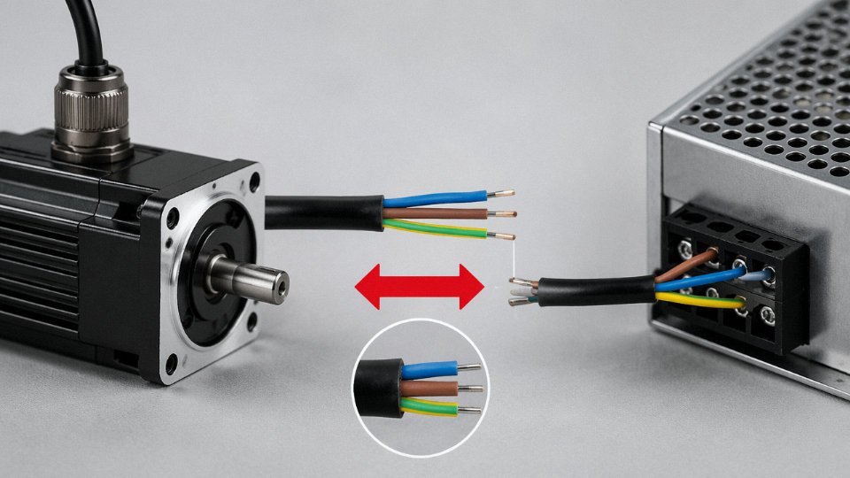
Under IEC 60446, the green-yellow stripe is exclusively reserved for protective earth — no other conductor in an IEC installation should use it, and no other color should be used for PE. North American NEC installations use bare copper or solid green. The problem shows up in older buildings and in equipment imported from regions with different historical conventions. Pre-2004 UK wiring used green alone, without yellow. Some legacy industrial installations have bare conductors that were originally grounded but have since been repurposed or left unconnected. Never assume. A two-second check with a voltage tester before touching any unfamiliar conductor is not overcaution — it’s just how experienced electricians work.
IEC 60446 reserves the green-yellow stripe exclusively for protective earth conductors and prohibits its use for any other function.True
IEC 60446:2010 explicitly designates the bicolor green-yellow combination as the mandatory identification for protective earth conductors, with prohibition on using this combination for any other conductor in an installation.
Why does my three-wire cable have four wires inside?
This comes up constantly with North American split-phase 240V circuits. A cable described commercially as “three-wire” in that context typically means three current-carrying conductors — black, red, and white — plus a bare equipment ground. So the physical cable has four conductors. The terminology reflects the number of current-carrying conductors rather than the total wire count. Meanwhile, in IEC single-phase wiring, “three-core” usually means live, neutral, and PE — which is also four conductors if you count the bare earth. The confusion is real and worth clarifying with your supplier before ordering, especially on international projects where the same shorthand means different things.
How do I know what cross-section I need?
Start with the maximum load current, then look up the appropriate ampacity from IEC 60364-5-52 tables for your specific installation method — clipped to surface, in conduit, buried direct, and so on all give different derating factors. From there, check voltage drop over the actual run length; IEC guidance generally targets no more than 4% on final circuits, though some sensitive equipment warrants tighter limits. Motor starting currents and cyclic loads add another layer. If the calculation is borderline, size up — the cost difference between 2.5 mm² and 4 mm² copper over a typical run is minor compared to a rewire later.
What is the difference between a PEN conductor and separate neutral and ground wires?
A PEN conductor carries both the neutral return current and the protective earth function in a single conductor, used in TN-C system configurations. IEC 60364-5-54 permits this only in fixed wiring with conductors of at least 10 mm² copper (or 16 mm² aluminum). The reason for the minimum size is mechanical — a broken PEN conductor in a TN-C system is genuinely dangerous because it simultaneously loses the neutral reference and the fault protection. Socket-outlet circuits must use separate N and PE conductors (TN-S arrangement), which is why most modern wiring projects default to TN-S or TN-C-S throughout, keeping the combined PEN only on the supply side upstream of the main distribution point.
Can the three wires in a power cable be different sizes?
Yes, and sometimes they have to be. In three-phase systems with significant harmonic distortion — variable speed drives, switch-mode power supplies, data center UPS systems — third-harmonic currents add rather than cancel in the neutral, so the neutral conductor can carry more current than any individual phase. Specifying a neutral at 1.5× the phase conductor cross-section is not unusual in those environments. The PE conductor sizing follows IEC 60364-5-54 minimum tables, which scale with the phase conductor area rather than matching it exactly. For phase conductors up to 16 mm², the PE is typically the same size; above that, the PE may be smaller. Assuming all three conductors must always match is a common procurement oversimplification — check the applicable standard for the specific circuit type and load profile before finalizing the specification.