Grab the wrong wire gauge on a residential or light commercial job and the consequences stack up fast. Undersized conductors overheat under sustained load, trip breakers repeatedly, and — in the worst cases — degrade insulation quietly until you have a fire hazard buried inside a wall. Oversized conductors cost more per foot than necessary, add weight, and make terminations at outlets and switches needlessly awkward. Neither mistake is dramatic at first; both get expensive.
14-2 wire is a 14 AWG, two-conductor cable most commonly used for 15-ampere, 120V branch circuits in residential and light commercial wiring — lighting circuits, standard outlet runs, and small dedicated loads. It carries a conductor resistance of roughly 8.29 ohms per 1,000 feet and is rated for 60°C in wet locations and up to 90°C in dry locations under NEC Article 334. At 120V, keep runs under about 50 feet to stay within a 3% voltage drop; at 240V, that practical limit extends to roughly 100 feet.
What makes this gauge interesting — and genuinely worth understanding before you specify it — is how much depends on installation context rather than the wire itself. The same spool of 14-2 NM-B that’s perfectly correct for a bedroom lighting circuit is a code violation one panel knockout over on a 20-amp kitchen outlet circuit. Understanding where that line sits, and why, is what separates a clean, inspection-ready installation from a callback.
Primary Electrical Applications: Lighting Circuits, Outlets, and 15-Amp Branch Circuits
14-2 wire is not a general-purpose solution for every residential circuit — it has a clear lane, and staying in that lane matters both for code compliance and for avoiding the kind of nuisance tripping (or worse, undersized protection) that creates callbacks and unhappy clients. Understanding where it fits, and why, turns gauge selection from guesswork into confident specification.
General Lighting Branch Circuits
This is the bread-and-butter application. Ceiling fixtures, recessed cans, wall sconces, track lighting in hallways — all of these typically land on a 15-amp circuit wired with 14-2 NM-B, and for good reason. A standard bedroom or hallway lighting circuit rarely pulls more than 400–800W in practice, even with older incandescent fixtures; with LED retrofits common now, loads are often a fraction of that. The 1,800W practical ceiling for a 15A/120V circuit (leaving 20% headroom per NEC 210.19) gives a comfortable buffer.
Recessed lighting runs deserve a note: when you’re daisy-chaining six to eight fixtures in a drop ceiling, the cumulative wire run can creep past 50 feet from the panel. At that point — with 14 AWG at roughly 8.286 ohms per thousand feet — voltage drop becomes a real consideration, not a theoretical one. For runs approaching 80–100 feet at 120V, either relocate the panel feed point or bump to 12 AWG conductors to stay inside a 3% drop threshold.
Duplex Receptacle Circuits in Bedrooms and Living Spaces
NEC Article 210 permits bedroom outlet circuits to be either 15-amp or 20-amp, which means 14-2 or 12-2 are both code-legal. Contractors running tract housing usually make this call based on labor-plus-material cost: 14-2 NM-B runs roughly 15–25% cheaper than 12-2 for the same footage (exact spread depends on copper pricing at the time of purchase), and the breaker slots are identical. For bedrooms where the anticipated load is phone chargers, lamps, and a laptop — not a window AC unit — specifying 14-2 is defensible and economical.
Where this reasoning breaks down is when a homeowner later plugs in a portable space heater or a mini-fridge. The wire is protected by the 15A breaker, so it won’t overheat — but the circuit nuisance-trips constantly. That’s a service call waiting to happen. In practice, I’d run 12-2 anywhere a kitchen-adjacent bedroom or a home office situation might push loads upward, even if the plan says otherwise.
Switch Loops and Single-Pole Switch Wiring
The standard switch loop — routing from the panel to the switch box, then up to the fixture — is one of the more commonly misunderstood 14-2 applications. In older installations, a two-wire cable was run from fixture to switch, using the white conductor as the always-hot feed to the switch and the black as the switched return to the fixture. Current NEC (2011 onward, Article 404.2) requires that white conductors used as hot be re-identified with black tape or black paint at both ends — a small step that matters during future troubleshooting. Skip it, and you’ve handed the next electrician a trap.
Under current NEC rules, a white wire in a switch loop used as a hot conductor must be permanently re-identified with black tape or marking at each visible point.True
NEC 200.7(C)(2) requires re-identification of white or gray conductors used as ungrounded (hot) conductors in single-pole switch loops using black or another appropriate color marking.
Newer construction typically runs a three-wire cable (14-3) to the switch location to include a neutral at the switch box — necessary for smart switches and dimmers that need a neutral reference. But for a plain single-pole mechanical switch controlling a ceiling fan or light, 14-2 remains standard and perfectly compliant.
Smoke Detectors, CO Detectors, and Life-Safety Circuits
Hardwired interconnected smoke and carbon monoxide detectors are required by building codes across the US, Canada, and most markets Jinda ships to internationally. These circuits draw almost nothing — a typical hardwired detector pulls under 50 mA in standby — but the wiring must be permanent and reliable. 14-2 NM-B is universally accepted for these circuits, often shared with a lighting circuit (depending on local AHJ interpretation) or run as a dedicated branch.
The interconnect wire between detectors is usually a separate 14-3 cable where the third conductor carries the signal, but the supply circuit itself is 14-2 from the panel.
Exhaust Fans, Garage Door Openers, and Ventilation Equipment
Bathroom exhaust fans, garage door openers, attic ventilation fans — these are single-device loads that rarely exceed 5–7 amps even at startup. All fit comfortably within a 15-amp circuit. Whether to wire them on a dedicated circuit or share with lighting depends on the load calculation and local code; a bathroom exhaust fan sharing a circuit with the vanity light is common and acceptable in many jurisdictions, while a garage door opener with a built-in outlet is often put on its own circuit to avoid nuisance tripping.
Outdoor Lighting via Conduit
When 14 AWG conductors are pulled through EMT or Schedule 40 PVC conduit to reach outdoor fixtures, the same 15-amp rating applies — but the product is different. You’re not using NM-B sheathed cable outdoors in conduit; you’re pulling individual THWN-2 or THHN conductors rated for wet locations. The conductor size is still 14 AWG, the circuit protection is still 15 amps, but the installation method and insulation system are distinct. Confusing sheathed NM-B cable with individual conduit conductors is a specification error worth flagging early with any procurement team ordering for mixed residential and light commercial projects.
Where 14-2 Wire Cannot Be Used: Code Limits, Load Calculations, and Safety Boundaries
Understanding where 14-2 wire cannot go is just as critical as knowing where it belongs. Misapplication doesn’t always trip a breaker immediately — sometimes it runs fine for months before it becomes a fire hazard or fails inspection. The boundaries below are not suggestions.
The 80% Continuous Load Rule and Why 1,440W Is the Real Ceiling
NEC 210.19 and 210.20 require that a branch circuit conductor not be loaded beyond 80% of its rating when serving a continuous load — defined as any load expected to operate for three hours or more. On a 15A circuit protected by a 15A breaker, that caps you at 12A continuous.
Worked out: 12A × 120V = 1,440W. That’s your practical ceiling, not 1,800W.
This matters more than most installers admit. A string of recessed LED fixtures totaling 900W sounds fine until you add a ceiling fan, a hallway outlet someone plugs a space heater into, and the calculation quietly falls apart. If you’re designing a circuit that will routinely run near its limit — even if the peak load technically fits under 15A — you should be looking at 12-2 from the start.
Kitchen and Bathroom Circuits: 14-2 Is Explicitly Prohibited
NEC 210.11(C) and 210.52 are unambiguous. Kitchen small-appliance circuits require 20A protection, and bathrooms require at least one dedicated 20A receptacle circuit. These rules exist because countertop appliances — toasters, coffee makers, microwaves — draw hard, sustained current that a 15A circuit can’t handle safely.
14-2 cannot serve these circuits. Only 12-2 satisfies the 20A requirement. This trips up remodel projects constantly: someone extends an existing kitchen circuit with 14-2, taps it to a new receptacle near the range, and it sails through until the inspector or, worse, an overloaded circuit catches up with them. There is no workaround here.
High-Draw 240V Loads: Dryers, Ranges, Water Heaters, HVAC
Electric dryers typically run on 30A circuits. Ranges and cooktops often require 40A or 50A. Water heaters and HVAC compressors pull sustained loads that demand 10 AWG or 8 AWG conductors. Running 14-2 to any of these is a serious fire hazard — the insulation will degrade from heat long before any properly-rated breaker trips.
Using 14-2 wire on a 30A circuit for an electric dryer is a fire risk because the wire can sustain damaging heat levels before the oversized breaker responds.True
14 AWG conductors are rated for 15A. On a 30A breaker, a fault or sustained overload can push current through the wire well beyond its safe ampacity. The breaker won't trip until 30A, by which point 14 AWG insulation is already thermally stressed — this is a documented cause of residential electrical fires.
Sub-Panel Feeders: Never, Regardless of Calculated Load
Even a small sub-panel feeding two or three circuits requires a minimum 10 AWG feeder. This is not negotiable, and the reason goes beyond present load: a sub-panel’s capacity can expand. Someone adds a circuit later, load grows, and the undersized feeder — which looked adequate on paper at installation — becomes a hidden hazard buried in a wall.
14-2 as a feeder is wrong even if the math appears to work today.
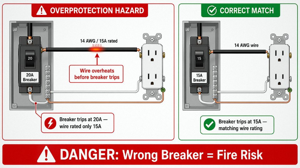
The Overprotection Trap: Wrong Breaker, Real Fire Risk
One of the most common wiring errors in residential remodels is installing 14-2 on a 20A breaker. It’s easy to see how it happens — the homeowner or unlicensed contractor grabs the wrong wire, or someone swaps a breaker without checking the wire gauge behind it. The circuit appears to function normally.
The problem is the breaker won’t trip until 20A. 14-2 is rated for 15A. In a fault condition, the wire carries current beyond its safe capacity before any protection activates. That gap is where fires start.
Temperature Derating and Environment Limits
NM-B 14-2 is listed for 60°C in wet locations and 90°C in dry locations, but “dry location” doesn’t cover every attic or conduit run. In attic spaces where ambient summer temperatures can push 50°C or higher in hot climates, the effective derating of insulation matters. Near recessed lighting cans without proper thermal barriers, the insulation sees radiant heat that compounds the problem.
In conduit, conductor ampacity must be derated based on fill — three current-carrying conductors in a conduit at 86°F ambient already drops 14 AWG effective ampacity to roughly 13A under NEC 310.15 adjustment factors. Add a warm environment and that margin disappears fast. If your installation involves any conduit run with multiple conductors, run the derating calculation before committing to 14-2.
14-2 UF-B for Underground and Outdoor Installations: Direct Burial Rules and Depth Requirements
UF-B and NM-B are both 14-2 cables, and from a distance they can look deceptively similar. In practice, they are built completely differently — and swapping one for the other underground is a code violation that tends to show up as insulation failure within a season or two, not immediately.
How UF-B Construction Differs from NM-B
NM-B (the standard Romex-style cable) wraps individually insulated conductors in a paper separator and an outer thermoplastic sheath, leaving small air gaps inside the jacket. That’s fine indoors. Underground, those voids wick moisture. UF-B eliminates the problem by co-extruding the conductors directly into a solid PVC jacket — each conductor is individually insulated first, then the whole assembly is encapsulated so the jacket bonds tightly around the conductors with no air gap. The resulting cable is rated sunlight-resistant and suitable for direct earth burial, which NM-B is explicitly not. The UF-B jacket compound is also formulated to resist the mechanical abrasion of soil contact and freeze-thaw cycling, which matters more in northern climates than most installers appreciate until they’ve dug up a failed run.
NEC Table 300.5 Burial Depth Requirements
Minimum burial depths for 14-2 UF-B under NEC Table 300.5 depend on what’s above the cable and how the circuit is protected:
| Installation Condition | Minimum Cover Depth |
|---|---|
| Direct burial, no protection | 24 in (610 mm) |
| Under a concrete slab (on grade) | 12 in (305 mm) |
| GFCI-protected, 120V, 15A or 20A residential | 12 in (305 mm) |
| Under a building or structure | 0 in (encased in conduit) |
The 12-inch reduction for GFCI-protected residential circuits is commonly used for garden lighting and landscape outlet runs — it’s legitimate, but the GFCI protection has to be upstream and functional, not just present on paper. Some inspectors also want to see warning tape or a physical identifier buried a few inches above the cable on any run shallower than 24 inches. Worth asking your local AHJ before the trench is backfilled.
Typical Outdoor Low-Load Applications
Most legitimate 14-2 UF-B installations are modest: garden lighting circuits, landscape spotlight feeds, irrigation controller power, outdoor outlet posts on a deck or patio perimeter, and occasionally a detached garage or garden shed subfeed where the total load stays well within 15 amperes. A typical scenario might be a homeowner running a single 20-foot landscape circuit to three 45-watt spotlights — that’s well under 2 amps, and the limiting factor is more often voltage drop on long skinny runs than current capacity. At 120V and 15 amps, the practical run length for less than 3% voltage drop sits around 50 feet (roughly 15 m); if the garden lighting circuit stretches past that, either step up to 12 AWG or move to a low-voltage lighting system instead.
GFCI Protection: Not Optional
NEC 210.8(A) requires GFCI protection for all outdoor receptacles and for circuits serving wet or damp locations. There is no burial depth or conduit arrangement that exempts a 14-2 UF-B outdoor circuit from this requirement. The GFCI device — whether a breaker, a receptacle with GFCI function, or an inline unit — must be part of the circuit before any outdoor outlet or load, regardless of how deep the cable is buried or how short the run is.
A 14-2 UF-B circuit feeding outdoor outlets is exempt from GFCI requirements if buried at least 24 inches deep.False
NEC 210.8(A) requires GFCI protection for all outdoor receptacles regardless of burial depth. Depth requirements under NEC Table 300.5 govern physical protection of the cable; they do not substitute for or waive shock-protection requirements.
Splice and Connection Rules for Buried Runs
Underground splices in 14-2 UF-B are prohibited by NEC 300.5(E) unless housed in a listed underground splice kit or a junction box brought to grade. This catches people on long landscape runs where the wire runs short and the temptation is to wire-nut and bury the joint. Moisture infiltration at an unlisted underground splice is slow and unpredictable — the circuit may work fine through a dry summer and fail the following spring. Use a waterproof direct-bury splice kit rated for the application, or plan the trench length before pulling wire.
International Equivalents for Export and Cross-Border Projects
Outside North America, the UF-B category doesn’t exist as a designation. Projects in the UK, Australia, the EU, or export markets typically specify armored or sheathed cables to IEC 60502 or BS 7846. The conductor cross-section equivalent to 14 AWG is 2.5 mm² — close enough for most circuit calculations, though you should verify current ratings against the specific installation method and ambient temperature correction factors in the applicable standard, since those vary more between IEC and NEC than the wire size difference alone would suggest. Jinda produces 2.5 mm² cables in both unarmored sheathed configurations and armored variants (SWA and AWA constructions) suited to direct burial in international projects, with documentation structured for both IEC and project-specific procurement requirements.
Voltage Drop, Run Length, and Circuit Design: Engineering 14-2 Circuits for Real-World Performance
Code compliance gets you a passing inspection. Actual engineering gets you a circuit that still performs correctly ten years later when someone plugs in a space heater and flips on the overhead lights at the same time. Those are different targets, and 14-2 wire sits right at the edge where they diverge.
The Voltage Drop Equation and What It Actually Tells You
The standard formula for a single-phase circuit is:
VD = (2 × L × R × I) / 1,000
where L is the one-way run length in feet, R is conductor resistance in ohms per 1,000 feet, and I is load current in amperes. For 14 AWG copper, R is 8.286 Ω/1,000 ft. The factor of 2 accounts for both the hot and neutral conductors carrying current.
Walk through a real example: a 40-foot run feeding a 12A load.
VD = (2 × 40 × 8.286 × 12) / 1,000 = 7,954.6 / 1,000 ≈ 7.95V
On a 120V circuit that’s roughly 6.6% drop — nearly double what NEC recommends for a branch circuit alone. That calculation should stop you cold before you pull a single foot of wire.
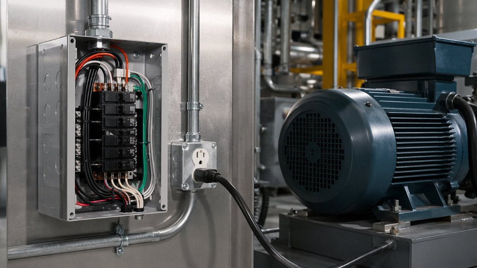
NEC Guidance vs. Engineering Reality
NEC doesn’t mandate a specific voltage drop limit — it recommends no more than 3% on branch circuits and no more than 5% combined across feeder and branch. On a 120V circuit, 3% is 3.6V. That’s the number to design to, not a soft suggestion to ignore when the run is “close enough.”
The threshold run length shifts significantly with load. Here’s where 14-2 crosses the 3% line at various currents:
| Load (A) | Max One-Way Run at 3% VD, 120V | Practical Note |
|---|---|---|
| 8 A | ~76 ft (23 m) | Typical lighting circuit, lightly loaded |
| 10 A | ~61 ft (18.5 m) | Mixed lighting + receptacle circuit |
| 12 A | ~51 ft (15.5 m) | Near-capacity branch, common in residential |
| 15 A | ~40 ft (12 m) | Full-rated load; seldom sustained continuously |
These figures depend on conductor temperature and actual cable resistance, which can shift a few percent in very cold conduit or under sustained load. Treat them as planning thresholds, not guarantees.
When 12-2 on a 15A Breaker Makes More Sense
This is a judgment call that gets skipped too often. If a lighting circuit runs more than 70–75 feet to a remote fixture — say, out to a detached garage or a far corner of a large warehouse bay — pulling 12-2 on a 15A breaker is often the more economical long-term decision. The wire costs more upfront, somewhere in the range of 15–30% more per foot depending on copper pricing at the time, but you avoid the callback when the homeowner or facility manager complains that the lights at the end of the run are visibly dim. Rewiring after the fact is never cheap.
NEC recommends no more than 3% voltage drop on branch circuitsTrue
NEC 210.19(A) Informational Note No. 4 recommends limiting branch circuit voltage drop to 3%, and combined feeder plus branch drop to 5%, though these are not enforceable code mandates.
Balancing Load Across Multiple Outlets
A single 14-2 branch circuit can feed up to 10 duplex receptacles under NEC’s general rules. For load calculation purposes, NEC Article 220 assigns 180 VA per general-purpose receptacle outlet. Ten outlets therefore contribute 1,800 VA of calculated load — which at 120V works out to 15A, exactly the breaker rating. In practice, not every receptacle will be loaded simultaneously, but in a home office or workshop where multiple devices run concurrently, that diversity assumption evaporates fast.
Power Factor and Inductive Loads: Use VA, Not Watts
LED drivers, ceiling fan motors, and older fluorescent ballasts all introduce a power factor below 1.0. A fixture labeled “60W” with a 0.7 power factor actually draws roughly 85–90 VA from the circuit. If you size a 14-2 circuit based on watt ratings alone, you’re underestimating the apparent current demand, which can cause nuisance tripping and accelerates insulation aging at the connections. Always pull the VA or current draw from the driver spec sheet when you have it. When you don’t, budget at least a 15–20% margin on inductive loads.
Short version: design for VA, protect with the right breaker, and don’t let the nominal wattage label do your load calculation for you.
Material Specifications, Standards Compliance, and International Certification Landscape
Buying cable off a spec sheet is one thing. Receiving the right product at the dock — and being able to prove it to an inspector or an end client — is something else entirely. For 14-2 wire, the gap between “roughly correct” and “fully compliant” can mean a failed listing inspection, a rejected shipment, or a rework cost that erases the margin on the whole job.
Conductor Form: Solid vs. Stranded, and Why the PO Has to Say Which
NEC Article 334.104 specifies solid conductors for NM-B in fixed branch-circuit wiring. That means a single 14 AWG solid copper conductor per current-carrying phase — not stranded, not compressed, not flex-rated. Stranded 14 AWG does appear in UL-listed armored cable (Type AC or MC) and in flexible cordage, where Class B stranding applies: 7 individual strands of 26 AWG twisted together to produce the equivalent cross-section. The two constructions are not interchangeable in the field, and they’re not interchangeable on a purchase order either. A procurement document that just says “14-2 wire” without specifying solid or stranded is an invitation for a substitution argument with a supplier. Specify it explicitly, every time.
Copper Purity: Where the Standard Sits and Where Premium Specs Don’t Buy You Much
The baseline for North American listed cable is electrolytic tough pitch (ETP) copper — minimum 99.9% purity — per ASTM B3 for solid conductors or ASTM B8 for stranded. That’s the standard you’ll find behind every UL-listed NM-B or UF-B product from a reputable manufacturer.
Oxygen-free copper (ASTM B170, typically 99.95%+ purity) gets specified occasionally in premium industrial or signal-critical applications. At 14 AWG for a 15-amp power circuit, though, the conductivity difference is negligible — we’re talking about a fraction of a percent improvement in resistivity at a meaningful cost premium. Save the OFC specification for applications where it actually matters.
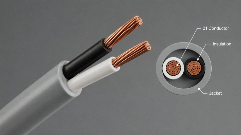
Insulation and Jacket Materials
Individual conductor insulation in most NM-B is either THHN (15-mil nylon jacket over PVC) or THWN-2 (moisture-resistant PVC with nylon). The THWN-2 rating gives you 90°C dry / 75°C wet performance and is what allows NM-B to carry a 90°C dry rating even though the cable assembly itself is derated to 60°C in wet locations per NEC Article 334. The outer jacket on NM-B is a flame-retardant PVC compound. UF-B uses a different approach — a solid LLDPE or sunlight-resistant PVC encapsulant that surrounds each conductor directly, which is why you can’t just strip UF-B like NM-B and expect separate conductors to slide out cleanly.
Listing Marks: What to Actually Look at on Incoming Product
For the North American market, NM-B must be listed to UL 719; UF-B falls under UL 493. Canadian market shipments require CSA C22.2 No. 131. The jacket print should show the listing mark, conductor gauge, voltage rating (600V), conductor count, insulation type (e.g., “14/2 NM-B WITH GROUND”), and sequential footage markings. When you’re inspecting an incoming pallet, check that the footage markers are present and legible — counterfeit or non-compliant cable sometimes drops the sequential footage printing, which is a fast visual flag.
UL 719 listed NM-B cable must display the UL mark, wire gauge, voltage rating, and footage markings on the outer jacketTrue
UL 719 (Standard for Nonmetallic-Sheathed Cables) requires jacket marking to include the listing mark, conductor designation, voltage rating, and sequential footage or meter marks as a condition of listing.
International Standards Cross-Reference
This is where procurement gets genuinely complicated for international projects. The direct metric equivalent to 14 AWG is 2.08 mm² actual cross-section — but no major IEC standard uses 2.08 mm². The nearest metric standard conductor size is 2.5 mm², which is what IEC 60227 (PVC-insulated cables for fixed wiring), IEC 60502-1 (power cables up to 1 kV), BS 6004 (UK), and AS/NZS 5000.1 (Australia/New Zealand) all specify at that tier. In practice, a 2.5 mm² conductor is slightly oversized relative to 14 AWG, which is generally conservative and acceptable — but the project specification needs to call out which standard governs, because current ratings, installation methods, and derating tables differ between NEC-based and IEC-based systems. Swapping conductor sizes between standards without rechecking the ampacity tables is a real mistake that shows up more often than it should.
Jinda’s Production Capability and International Procurement Value
Jinda’s manufacturing infrastructure covers both NEC-adjacent and IEC-compliant production, with ISO 9001 quality management across five production bases in China. For buyers sourcing 14 AWG / 2.5 mm² equivalent cable in volume — project quantities, OEM labeling programs, or multi-country distribution — the ability to produce to a customer-specified standard (UL, IEC, BS, AS/NZS) from a single supplier simplifies certification documentation and incoming inspection significantly. OEM jacket printing, custom reel lengths, and standard-specific conductor colorings are all available for bulk orders. For procurement managers running international projects, that kind of flexibility matters more than it might seem when you’re reconciling inspection requirements across three different job-site jurisdictions.
Installation Best Practices: Stapling, Protection, Connections, and Inspection Checklist
Getting 14-2 NM-B from the spool to a passing inspection involves a chain of small decisions that compound quickly when they go wrong. A loose staple here, a nicked conductor there, and you’re looking at a callback, a failed rough-in, or — in the worst case — a connection that runs hot for two years before starting a fire inside a wall cavity. None of this is exotic; it’s the stuff that separates a clean install from a problem install.
Stapling and Support Intervals
NEC 334.30 is clear: NM-B cable needs support within 12 inches (305 mm) of every box or fitting and at intervals no greater than 4.5 feet (1.37 m) along the run. In practice, most journeymen work in roughly 4-foot intervals and hit the 12-inch requirement first before running toward the next box. That rhythm is fine.
The fastener choice matters more than people think. Insulated cable staples — the kind with a nylon or plastic saddle — are the right tool. Uninsulated steel staples might hold the cable mechanically, but under lateral load or thermal cycling, the bare metal edge can work into the jacket over time. One staple driven at a slight angle is enough to start the damage. It’s a slow failure mode, but it’s real.
Protecting the “Nail Zone”
Where a cable runs through a bored hole in a stud or joist and that hole is within 1.25 inches (32 mm) of the face of the framing member, NEC 300.4 requires physical protection. The standard solution is a steel nail plate — sometimes called a stud guard — rated to UL 514B. These are typically 1/16-inch steel minimum and get driven flush over the bore location before drywall goes up.
This is consistently one of the top deficiencies on residential rough-in inspections. Inspectors flag it routinely, partly because it’s easy to miss during a fast frame-out and partly because some crews simply forget on runs through shallow nailers. Mark your nail-zone locations with a lumber crayon before the drywaller arrives if your inspection schedule is tight.
Bending Radius
NEC 334.24 sets the minimum bend radius at five times the cable’s outer diameter. For a typical 14-2 NM-B with a jacket OD around 0.375 inches (9.5 mm), that works out to roughly 1.875 inches (48 mm). Sharp 90-degree bends stuffed into a corner look fine initially, but cracked insulation from overstressing the jacket is an inspection failure — and cracked insulation at a bend point inside a finished wall is a problem you won’t find again until something goes wrong.
Termination Torque
Since NEC 110.14(D) took effect, torque requirements are no longer optional on listed devices. For 14 AWG conductors on standard 15A receptacles and switches, the termination torque is typically around 20 in-lb (2.26 N·m) — confirm against the device label, because values vary by manufacturer. A proper torque screwdriver or a calibrated torque tool is now required equipment on inspected work. Specify torque values in project quality plans; don’t assume crews carry calibrated tools by default.
Stripping and Conductor Integrity
Strip 3/4 inch (19 mm) for screw terminals, 1/2 inch (13 mm) for push-in connectors. The nick issue is underrated — a stripping nick reduces the conductor cross-section at exactly the point that sees the most mechanical stress during device installation. Under repeated thermal cycling from load variation, nicked conductors can fail progressively. Use a quality wire stripper with a calibrated stop, not a utility knife.
Pre-Inspection Checklist
Run through these before calling for rough-in:
- All boxes accessible and box fill calculated — no buried junction boxes
- Cable clamps fully engaged at every knockout with the cable jacket inside the box, not just the conductors
- White conductors re-identified with black tape on every switch loop where white is used as a hot
- GFCI protection confirmed on all required circuits (bathrooms, kitchen countertop circuits, garage, outdoor, and any crawlspace or unfinished basement outlets)
- Every circuit verified against the panel schedule — no 14-2 cable landed on a 20A breaker under any circumstances
Using uninsulated steel staples on NM-B cable instead of insulated cable staples can damage the jacket under lateral mechanical load and thermal cycling.True
Uninsulated steel staples have a bare metal edge that can cut into the thermoplastic jacket of NM-B cable when subjected to lateral force or repeated thermal expansion and contraction cycles, potentially compromising insulation integrity over time.
That last point on the checklist — 14-2 on a 20A breaker — is a hard stop. The overcurrent protection must match the conductor ampacity, not the device rating. It’s a wiring error that occasionally shows up when someone swaps a tripped 15A breaker for a 20A “because that’s what was on the truck,” and it removes the protection the wire depends on to stay within its thermal limits.
Frequently Asked Questions About 14-2 Wire
Can I use 14-2 wire on a 20-amp breaker?
No. This is one of the most dangerous wiring shortcuts in residential electrical work, and it gets made more often than it should. NEC 240.4(D)(3) is explicit: 14 AWG copper conductors require overcurrent protection at 15 amps maximum. The logic is straightforward — the breaker is supposed to protect the wire, not the load. A 20A breaker will carry somewhere between 16 and 20 amps continuously before tripping, and 14 AWG copper will be running well above its thermal limit the entire time. The insulation degrades, the connections at outlet terminals and switch boxes heat-cycle repeatedly, and you get a fire risk that may not show up for months. By then, the cause is hard to trace. Don’t do it.
14 AWG copper wire is rated for a maximum of 15 amps overcurrent protection under NEC 240.4(D)(3)True
NEC 240.4(D)(3) specifically lists 14 AWG copper as requiring 15A maximum overcurrent protection regardless of insulation temperature rating.
What is the difference between 14-2 and 14-3 wire?
The conductors. 14-2 carries two insulated conductors — black (hot) and white (neutral) — plus a bare copper ground. That’s your standard single-pole, 15A branch circuit. 14-3 adds a red conductor, which opens up a different range of applications: 3-way switching (where the red and black serve as travelers), split-wired duplex receptacles where two circuits share one box, and some 240V low-draw circuits that need a neutral. The physical diameter of the cable is slightly larger with 14-3 because of the additional conductor, which matters when you’re pulling through conduit or stuffing boxes. Plenty of people grab the wrong reel on a job. Check before you pull.
How many outlets can be on a 14-2 circuit?
The NEC doesn’t set a hard maximum outlet count, which surprises some people. In practice, the 80% continuous load rule and the 180VA per receptacle demand factor from NEC 220.14(I) work out to roughly 8 receptacle outlets as a practical ceiling on a 120V/15A circuit — that keeps you under the 1,440W continuous limit. In real residential wiring, a bedroom circuit might have 6 to 8 outlets and run fine for decades because the actual simultaneous load is low. The number that matters is load, not outlet count.
Is 14-2 wire safe for a bathroom?
For the lighting circuit, yes. A bathroom exhaust fan on its own dedicated 14-2 circuit, or a light fixture on a 15A circuit — both are fine. What’s not permitted is running 14-2 to the receptacle outlets. NEC 210.11(C)(3) requires at least one 20A branch circuit dedicated to bathroom receptacles, which means 12-2. Running both a 14-2 lighting circuit and a 12-2 receptacle circuit in the same bathroom is completely standard and code-compliant, provided each lands on the correct breaker and the 14-2 circuit never picks up the outlets.
What does the color of the 14-2 NM-B jacket indicate?
Starting with NEC 2001, the industry adopted a jacket color convention: white for 14 AWG, yellow for 12 AWG, orange for 10 AWG, black for 8 or 6 AWG. Most major US manufacturers follow this, and it’s genuinely useful on a busy job site. That said, NEC doesn’t mandate the colors — it’s industry practice, not code. Old stock, foreign-manufactured cable, or specialty products may not follow it. Always read the jacket print. The AWG and conductor count are printed on every compliant cable, and that’s the authoritative reference.
Can 14-2 UF-B be used for a detached garage?
Technically yes, if the total circuit load stays at 15A or below. In practice, most garages are a bad candidate for 14-2 UF-B. One mid-size air compressor or a vehicle battery charger can pull 12 to 15 amps on its own, leaving nothing for lighting or a receptacle. The smarter default for a detached garage feed is 12-2 UF-B on a 20A breaker — it costs modestly more and gives you room to actually use the space. Reserve 14-2 UF-B for outbuildings that genuinely have only lighting loads: a small shed, a garden structure, a post light circuit.
How far can 14-2 wire run without voltage drop issues?
At 12 amps continuous on a 120V circuit, the 3% voltage drop threshold falls at roughly 50 to 52 feet of one-way run length, depending on ambient temperature and the actual conductor resistance of the specific cable. That’s not very far — a circuit in a long hallway or a room at the end of a house can blow past that without anyone thinking twice. At 240V, the same wire handles about double that distance for the same percentage drop because the voltage is twice as high relative to the resistive loss. For anything pushing beyond 50 feet at 120V, upsize to 12 AWG or reroute the circuit to shorten the run. Undersized-for-length circuits typically show up as flickering lights under load or warm dimmers — subtle until they’re not.