Miswire a receptacle — swap neutral and ground, for instance — and you may not know until someone gets hurt or a piece of equipment fails in a way that looks random but isn’t. On a busy production floor, a single miswired outlet can feed weeks of intermittent faults into a machine control circuit before anyone thinks to check the receptacle rather than the machine. The downstream cost in troubleshooting labor, scrap, and unplanned downtime regularly exceeds what it would have cost to train the installer properly in the first place.
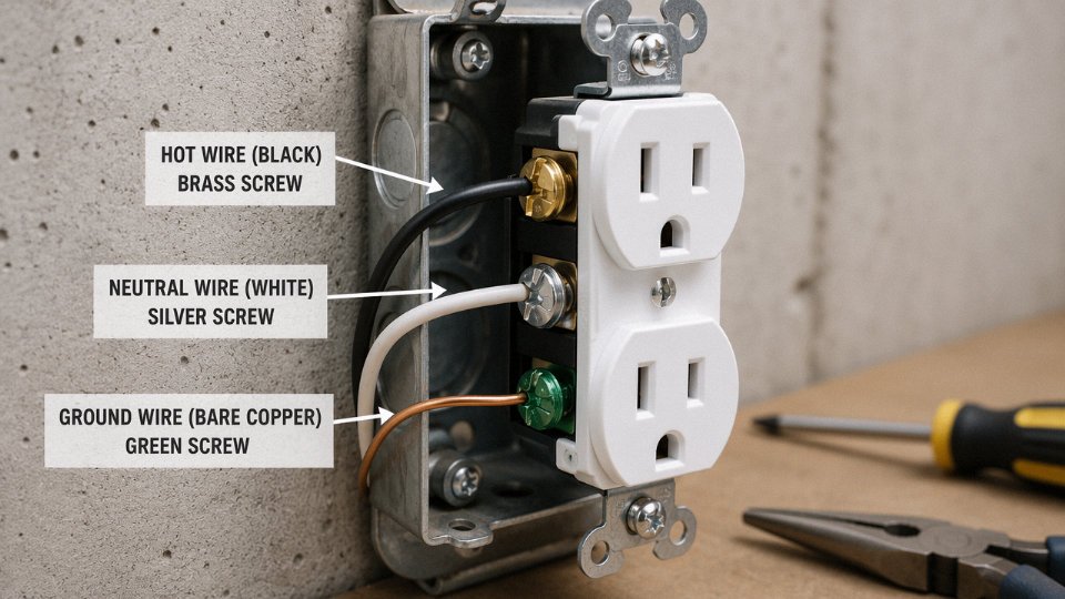
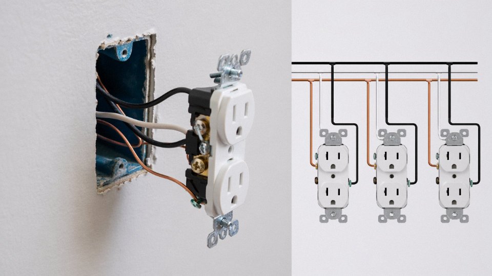
Every standard outlet in a residential or light-commercial circuit has three wires: a hot (black in North America, brown in the UK and EU), a neutral (white in North America, blue in the UK and EU), and a ground (bare copper or green). The hot carries current to the load; the neutral returns it under normal operation; the ground sits idle until a fault occurs, at which point it provides a low-impedance path that forces the breaker or fuse to open before voltage reaches anything a person might touch.
What most people — including some electricians who should know better — miss is that these three wires are not interchangeable, not equivalent in function, and not governed by the same electrical rules. The ground wire in particular is widely misunderstood: it carries almost no current in normal operation, yet its resistance, its continuity, and the quality of its terminations are arguably the most safety-critical details in the entire circuit. That gap between apparent simplicity and actual consequence is worth working through carefully.
How the Hot Wire Delivers Current: Voltage Levels, Insulation Ratings, and Real-World Risks
The hot wire is the energized conductor — it carries voltage from the breaker panel to the outlet at all times the circuit is live, whether anything is plugged in or not. That distinction matters. Neutral carries current only when a load is connected and completing the circuit. The hot wire sits at potential continuously, which is exactly why touching it without isolation kills people.
Voltage level varies by region in ways that directly affect how the cable has to be built. North American branch circuits run at 120 V to ground (240 V between the two hots in a split-phase system). Most of Europe, Asia, and Australia operate at 220–240 V. That difference roughly doubles the electrical stress on insulation. Higher voltage means thinner insulation is more likely to fail under the same physical abuse — abrasion, flexing, rodent damage, thermal cycling — so cable manufacturers compensate with increased wall thickness or higher-grade dielectric materials. A cable rated adequate for 120 V service may still meet the voltage class for 240 V, but the safety margins shrink, and in high-ambient-temperature environments like machine rooms or conduit bundles running full load, that margin can disappear faster than the datasheet suggests.
Insulation Rating Classes and What They Actually Mean on the Shelf
The voltage class stamped on a cable — 300 V or 600 V for typical branch circuit wiring — is the first thing to check, but it’s not the only thing. Temperature rating matters just as much in practice, sometimes more. The three common ratings you’ll see are 60°C, 75°C, and 90°C, and they’re not interchangeable even if the conductor gauge is identical.
THHN (thermoplastic, high heat-resistant, nylon-jacketed) is rated 90°C in dry locations, 75°C in wet. THWN covers wet locations to 75°C. NM-B — the standard Romex-type cable used in US residential walls — uses 90°C-rated conductors inside, but the NEC limits the assembly’s ampacity to the 60°C column because the jacket traps heat. That’s why a 12 AWG NM-B circuit is limited to 20 amps, not the higher figure you’d get from 12 AWG THHN pulled in open air. Procurement teams sourcing cable for projects outside their home market sometimes miss this and end up with a product that passes the voltage check but underperforms thermally once it’s bundled in conduit or stapled in a wall cavity.
XLPE (cross-linked polyethylene) insulation pushes the operating temperature to 90°C continuously and handles higher fault-current temperatures than PVC. LSZH (low-smoke, zero-halogen) compounds are increasingly specified for commercial and industrial installations where fire safety codes restrict halogenated materials. Neither XLPE nor LSZH is automatically “better” — they serve different risk profiles, and specifying one when the project calls for the other wastes money or creates a compliance problem.
Color Codes by Region — and Why Mixing Them Up Is Genuinely Dangerous
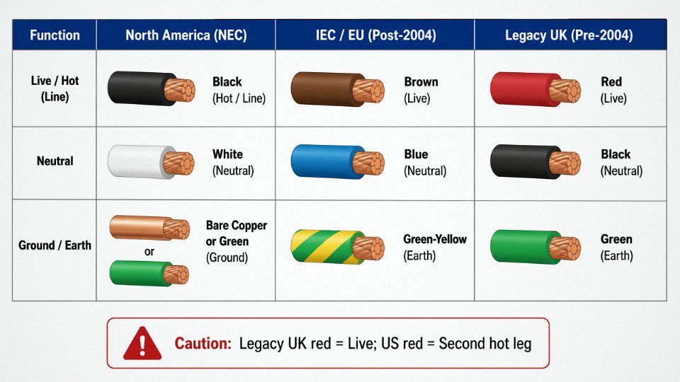
In the US and Canada, the hot wire is black on a standard 120 V circuit. A second hot leg on a 240 V circuit is typically red. IEC-compliant wiring (EU, much of Asia, newer Australian installations) uses brown for live. Older UK installations — anything pre-2004 — used red for live, which collides directly with the US convention where red usually means a second hot leg, not the only hot conductor. Older Australian wiring used red for active as well.
In IEC-compliant wiring systems, brown insulation identifies the live (hot) conductorTrue
IEC 60446 and the harmonized European CENELEC standard HD 308 S2 assign brown to the live conductor, replacing the older red used in pre-2004 UK wiring. This is now standard across EU member states and many countries that have adopted IEC color conventions.
Mixing color conventions on a retrofit or international project is a real failure mode, not a theoretical one. A maintenance technician trained on US wiring who encounters brown-live IEC cable without a briefing can misidentify the hot as an earth or neutral and work live on what they believe is a safe conductor.
Overload and Arc Fault Risk on the Hot Conductor
Undersized hot conductors are responsible for a significant share of residential electrical fires. The physics is straightforward: resistance heating scales with I²R, so a conductor carrying more current than its ampacity rating dissipates heat into the insulation. PVC insulation begins softening somewhere in the 70–90°C range depending on compound grade. Once the insulation softens or cracks, the risk of arcing to a nearby conductor or combustible material increases sharply.
Arc faults are particularly dangerous because a standard thermal-magnetic breaker may not trip. The arc current can be intermittent and below the breaker’s trip threshold while still generating temperatures above 6,000°F at the arc point. That’s why AFCI (arc fault circuit interrupter) breakers are now required for most bedroom and living area circuits in the US under recent NEC editions — they detect the waveform signature of arcing, not just overcurrent.
For a practical benchmark: a 12 AWG THHN copper hot conductor, 600 V rated, 90°C, is the standard choice for a 20-amp branch circuit in US commercial or residential work. At that gauge and with copper conductivity around 5.8 × 10⁷ S/m, voltage drop stays within the NEC’s informal 3% guideline out to roughly 50–65 feet depending on the actual load — shorter if you’re running near full ampacity continuously, longer if the circuit is lightly loaded. Beyond that range, stepping up to 10 AWG is the practical call, not a theoretical one.
What to Specify When Sourcing Internationally
When procuring hot-wire-bearing cable from overseas suppliers, the datasheet needs to show voltage class (600 V minimum for most branch circuit applications), temperature rating, conductor material (oxygen-free or electrolytic tough pitch copper, not aluminum unless explicitly designed and code-compliant for that application), insulation material and compound grade, and the third-party certification mark relevant to the destination market — UL for North America, CE/HAR for Europe, SAA for Australia. A supplier who can’t produce a test report showing insulation breakdown voltage tested to at least 2× rated voltage plus 1,000 V is a supplier worth being cautious about.
Insulation material choice — PVC, XLPE, or LSZH — should be driven by the installation environment, the applicable fire code, and the ambient temperature the cable will actually see in service, not just what’s cheapest or what the supplier defaults to.
What the Neutral Wire Actually Does: Return Path, Voltage Reference, and Why It Still Carries Current
The neutral wire is the one people dismiss. It’s white (or gray, or blue depending on where you are), it connects to the silver screw on the outlet, and the common assumption is that it’s somehow the passive half of the circuit — the wire that just sits there while the hot wire does the work. That assumption has caused fires, destroyed equipment, and left electricians chasing phantom faults for hours.
Here’s the reality: under normal load, the neutral carries exactly the same current as the hot wire. It has to. Current flowing out through the hot must return through the neutral to complete the circuit back to the transformer’s center tap — or, in IEC systems, back to the earthed star point of the distribution transformer. Ohm’s law doesn’t offer exceptions. If 12 amperes flows to your load, 12 amperes flows back. The neutral is not inactive; it’s just the return leg.
The Neutral-Ground Bond and Why It Only Happens Once
In North American residential systems, the neutral conductor is bonded to the grounding system at exactly one point: the main service panel. This single-point bond is deliberate and code-specific. It establishes the neutral as the voltage reference point for the entire system — the thing that anchors 120 V “above ground” and prevents the hot-to-ground voltage from floating unpredictably. Critically, this bond must not be repeated at subpanels. If it is, neutral return current finds two parallel paths home, and one of them runs through what should be a ground-only conductor. You end up with current on grounding conductors, which creates shock hazards on equipment enclosures and can interfere with ground-fault protection. It’s a straightforward rule with messy consequences when ignored.
In North American systems, the neutral-ground bond must exist only at the main service panel, not at subpanels or downstream distribution points.True
NEC Article 250 requires the neutral-to-ground bond at the service disconnect only. Bonding at subpanels creates objectionable neutral current on grounding conductors, a code violation under NEC 250.6 and a real shock and equipment hazard.
What a Loose or Corroded Neutral Actually Does to Your Circuit
A degraded neutral connection is nastier than a failed hot, in some ways. A failed hot simply kills the load. A loose or high-resistance neutral starts misbehaving under load — the neutral-to-ground voltage climbs above the near-zero it should sit at, lights flicker or dim in a load-dependent pattern, and the connection point itself heats up because it’s now dissipating power that the conductor should be passing freely. In multi-wire branch circuits (MWBCs), which share a single neutral between two hot legs on opposite phases, a broken neutral is genuinely dangerous: both loads end up in series across 240 V rather than each seeing 120 V. If the loads are unequal — a lamp on one leg, a space heater on the other — the heavier load sees reduced voltage and the lighter load sees voltage well above its rating. Equipment destruction or fire is a realistic outcome, not a theoretical one.
Corrosion is the more common villain than outright breakage, particularly in humid environments or anywhere aluminum wiring was used. Aluminum neutrals develop oxide layers at terminations over years of thermal cycling. The resistance creeps up gradually, which is why the fault often shows up as intermittent rather than catastrophic.
Color Codes Across Regions — and Why Confusion Costs You
North America uses white or gray for neutral. IEC/EU systems (post-2004 harmonization) use blue. Older UK wiring used black for neutral, which is now reserved in IEC systems for a phase conductor. Australian practice has shifted from black neutral to blue, aligning with IEC, but legacy installations still show black. On international projects — a factory fitted out with a mix of European switchgear, North American cable runs, and Australian motor starters — the color-code mismatch is a real installation hazard. An electrician trained on IEC conventions who encounters old UK black-neutral wiring can incorrectly treat it as a phase conductor. The fix is straightforward: label cables at both termination points with function markers, not just color, and specify color codes explicitly in procurement documents rather than assuming the vendor’s home-country standard.
Three-Phase Neutrals and the Sizing Question
In a balanced three-phase system — equal loads on all three phases — the phase currents cancel vectorially and the neutral carries near-zero current. That’s the textbook case. Real plants rarely run balanced. Single-phase loads pulled from a three-phase panel (lighting circuits, office equipment, smaller machines) almost always create some unbalance, and the neutral must be sized for the worst credible unbalance current, not the balanced-case theoretical zero.
There’s a further wrinkle: nonlinear loads like variable-frequency drives, switched-mode power supplies, and LED drivers generate triplen harmonics (3rd, 9th, 15th…) that add in the neutral rather than canceling. In a building heavily loaded with VFDs or server equipment, the neutral current can actually exceed the phase current. Undersizing the neutral in those applications — which happens when installers carry over residential intuitions into light-industrial or data-center settings — results in overheating and, eventually, insulation failure.
Procurement Note on Neutral Conductor Sizing
In most residential and light-commercial multi-conductor cable, the neutral is sized identically to the phase conductors: 14 AWG for 15 A circuits, 12 AWG for 20 A circuits in North American practice, with equivalent cross-sections in metric sizing (roughly 2.5 mm² and 4 mm² respectively in IEC conventions, though the exact current ratings depend on installation method, ambient temperature, and bundling). Some industrial cables legitimately use a reduced neutral — typically down to 50% of the phase conductor cross-section — but this is only code-compliant when the load is demonstrably balanced and free of significant harmonic content. If you’re specifying cable for a panel serving mixed loads and you’re not certain about harmonic analysis, the full-size neutral is the safe procurement default. The cost difference between a reduced and full-size neutral in a multi-conductor cable run is usually small; the cost of rewiring a harmonic-overloaded neutral after the fact is not.
The Ground Wire’s Job: Fault Current Path, Equipment Protection, and Why It Should Never Carry Normal Current
The ground wire is the one conductor in that cable that should read zero current on your clamp meter during every normal operating hour of a circuit’s life. That’s not a flaw — that’s the entire point. Its job is singular: sit dormant until something goes wrong, then provide a low-impedance path aggressive enough to push fault current through the overcurrent device and trip it before a person becomes the easier path to earth. One purpose, no ambiguity.
Normal Operation vs. Fault Conditions
Under normal conditions, current flows out on the hot conductor, returns on the neutral. The ground wire carries nothing. The moment a phase conductor contacts a grounded metal enclosure — a worn insulation spot inside a motor, a staple driven through a cable in the wall, a loose terminal that arcs against a panel chassis — the character of the circuit changes entirely. Fault current now has a second return path. If that path is the ground wire, it surges. The overcurrent device sees a current spike well above its rating and clears the fault in milliseconds, anywhere from roughly 0.008 to 0.1 seconds depending on breaker type and fault magnitude.
Without a grounding conductor, that same fault energizes the appliance casing. The voltage sits there, waiting. A technician grabs the enclosure while touching a grounded surface — maybe a conduit, maybe a wet concrete floor — and becomes the fault-current path himself. The breaker may never trip at all, because the impedance through a human body is high enough that the fault current stays below the trip threshold. That scenario is how electrocution fatalities happen in industrial facilities, and it’s entirely preventable.
A ground wire carries no current under normal operating conditions and only conducts during a fault eventTrue
By design, the equipment grounding conductor (EGC) provides a fault-current return path. In a properly wired circuit with no insulation failure, no current flows through it. Measuring current on a ground wire during normal operation indicates either a wiring error, a ground fault, or a leakage current problem worth investigating immediately.
Grounding Conductor vs. Grounding Electrode System
This distinction trips up even experienced electricians. The grounding conductor — the green or bare copper wire running from each outlet back to the panel — is called the Equipment Grounding Conductor (EGC). It bonds equipment enclosures to the system neutral at the main service panel. It is a current-carrying fault path. The grounding electrode system is something else entirely: the copper rod driven into the earth outside the building, the metal water piping, or the concrete-encased electrode (Ufer ground) cast into a foundation. That system ties the electrical service to earth potential and provides a reference for the utility supply, but it is not the primary fault-clearing path under NEC-governed installations. Confusing the two leads to badly engineered installations — particularly in industrial retrofits where someone bonds equipment to a ground rod and calls it protected, when the rod’s soil resistance (easily 10–25 ohms in dry conditions) is far too high to reliably trip a breaker.
Sizing Rules You Actually Need
NEC Table 250.122 sets the floor, not the ceiling. For a 15 A circuit, 14 AWG copper is the minimum EGC. A 20 A circuit requires 12 AWG. Step up to a 60 A feeder and you’re at 10 AWG minimum. The underlying logic is that the EGC must carry enough fault current, for long enough, without burning open before the overcurrent device clears. Longer runs increase impedance; NEC 250.122(B) requires upsizing when the ungrounded conductors are upsized for voltage drop. In practice on industrial runs over roughly 150–200 feet, I’d calculate actual fault-loop impedance rather than just pulling minimum gauge from the table.
Bare Copper vs. Green Insulation
Bare copper EGC is permitted inside conduit or within the sheath of an armored or metal-clad cable — the mechanical enclosure provides physical protection. Run an EGC in conduit alongside insulated conductors and bare is fine. Pull individual conductors through open wiring, or use a multiconductor cable where the EGC sits alongside current-carrying conductors without overall sheathing, and green insulation is required so the conductor is identifiable at every termination point. IEC installations use green-yellow striped insulation, which is a global standard worth knowing if your facility runs both NEC and IEC-rated equipment — and mixing up a blue IEC neutral with a green-yellow earth during a panel termination is a real error with real consequences.
Why Conductor Integrity Over Long Runs Matters More Than Most Buyers Realize
Ground continuity is only as good as the weakest point in the conductor, and on a 500-meter cable drum that weak point is usually a cross-section inconsistency or a stranding defect that looks fine on the surface. Jinda’s manufacturing process holds conductor cross-section tolerance tightly across full production lengths, and the stranding geometry is designed for clean, reliable termination — meaning the conductor compresses predictably under a lug or screw terminal rather than birdcaging or presenting a reduced contact area. On a 30-meter branch circuit, a minor stranding defect might never show up. On a 200-meter industrial run, the same defect creates elevated impedance exactly where you need it lowest, and your ground fault protection becomes quietly unreliable long before any visible sign appears.
Wire Color Codes by Country and Electrical Standard: A Practical Reference for International Projects
If you’ve ever opened a junction box in a building that was wired by a different country’s standards, you already know the problem. The colors don’t match what you expect, and guessing wrong is not a recoverable mistake.
The table below gives you a working reference. Use it as a starting point — always verify live conductors with a calibrated meter before touching anything.
| Region / Standard | Live / Hot | Neutral | Protective Earth | Typical Supply Voltage | Governing Standard |
|---|---|---|---|---|---|
| USA / Canada | Black (or red for 240 V) | White or gray | Green or bare copper | 120/240 V | NEC (NFPA 70) |
| European Union | Brown | Blue | Green-yellow | 230 V | IEC 60446 / HD 60364 |
| UK post-2004 | Brown | Blue | Green-yellow | 230 V | BS 7671:2018 |
| UK pre-2004 (legacy) | Red | Black | Green | 240 V | Former BS 7671 |
| Australia / New Zealand | Brown (or red, older) | Blue (or black, older) | Green-yellow | 230 V | AS/NZS 3000 |
| China (three-phase) | Yellow, Green, Red (L1–L3) | Light blue | Green-yellow | 380/220 V | GB/T 6995, GB 50303 |
| Japan | Black | White | Green | 100 V | JIS C 3307 / JEAC |
The UK Color Transition and Why Legacy Buildings Still Bite People
The 2004 harmonization across EU member states — which the UK adopted before eventual regulatory divergence — replaced the old red/black/green scheme with brown/blue/green-yellow to align with IEC 60446. The intent was to reduce confusion for electricians working across borders. Reasonable goal.
The problem is that millions of buildings across the UK, Ireland, and parts of former British-influenced markets still have the old colors in their walls. In a partial renovation, you can end up with both systems in the same distribution board. A black wire in old UK wiring is a neutral. In current IEC wiring, black doesn’t appear in the standard at all — but an electrician trained post-2004 might reasonably assume it’s a phase conductor from some unlabeled run. That assumption causes faults. In practice, any building wired before roughly 2005 should be treated as “color unknown until tested.”
In post-2004 UK and EU wiring, a blue wire always indicates neutral.False
Blue indicates neutral in current BS 7671 and IEC 60446 wiring. However, in pre-2004 UK installations, blue was sometimes used for switched live conductors in lighting circuits, and in older harmonized cable it could appear as a phase. Color alone is never a reliable verification method in retrofit or mixed-age installations.
China’s GB Standard and Dual-Standard Production
China’s GB/T 6995 follows IEC 60446 closely for protective earth (green-yellow) and neutral (light blue), but the three-phase phase conductors — yellow, green, and red for L1, L2, L3 respectively — are worth knowing explicitly if you’re specifying switchgear or motor feeds sourced from Chinese manufacturers. The green phase conductor in a GB three-phase system will look, to an NEC-trained eye, like a ground wire. That’s a serious misread waiting to happen on any cross-border equipment installation.
Jinda produces cables to both GB and IEC standards across its production lines, which matters for export orders because color coding, insulation compound, and marking requirements all vary by destination standard — not just voltage rating.
A Short Procurement Checklist for Cross-Border Cable Orders
When you’re specifying cable for a project outside your home market, these four steps save rework:
- Specify the governing standard by name and year — “IEC 60446” or “BS 7671:2018+A2:2022” is more useful on a purchase order than “European standard.”
- Request a certificate of conformity that explicitly calls out color identification compliance. A test report for conductor resistance does not confirm color coding.
- Confirm insulation compound meets local fire safety requirements. LSZH (low smoke, zero halogen) is mandatory in many public buildings and transportation infrastructure per EN 50575 in Europe; standard PVC is not acceptable in those applications regardless of color compliance.
- For retrofit or expansion projects, physically trace and meter-verify every conductor before assuming the installed color code matches any standard — old or new.
Color codes exist to speed up safe work. Treat them as a useful shortcut that requires confirmation, not a substitute for measurement.
Wire Gauge, Current Capacity, and Voltage Drop: Sizing the Three Conductors Correctly for Any Circuit
Two constraints govern every conductor sizing decision: ampacity and voltage drop. They’re independent problems, and you have to satisfy both. Failing on ampacity means overheated insulation, potentially a fire. Failing on voltage drop means equipment running outside its rated voltage window — motors running hot, variable-frequency drives faulting, sensitive electronics behaving erratically. Neither failure announces itself immediately, which makes undersized wire one of the more insidious mistakes on the plant floor or in a residential fit-out.
Ampacity: The Thermal Ceiling
Ampacity is simply the maximum continuous current a conductor can carry without pushing its insulation past its rated temperature. For copper, that rating depends on insulation type — 60°C-rated insulation (older THHN installations, some flexible cords) is more conservative than 90°C-rated material, and the same physical wire carries meaningfully more current at the higher rating, though NEC 110.14(C) typically forces you to derate back to the 60°C column at terminations anyway unless the equipment is rated otherwise.
A working reference for copper conductors:
| AWG | Metric approx. | Typical ampacity (60°C) | Typical ampacity (90°C) |
|---|---|---|---|
| 14 | 2.5 mm² | 15 A | 20 A |
| 12 | 4 mm² | 20 A | 25 A |
| 10 | 6 mm² | 30 A | 35 A |
| 8 | 10 mm² | 40 A | 50 A |
These figures assume free air or standard conduit fill. The moment you start bundling, the numbers shift.
Derating for Conduit Fill — A Frequently Ignored Multiplier
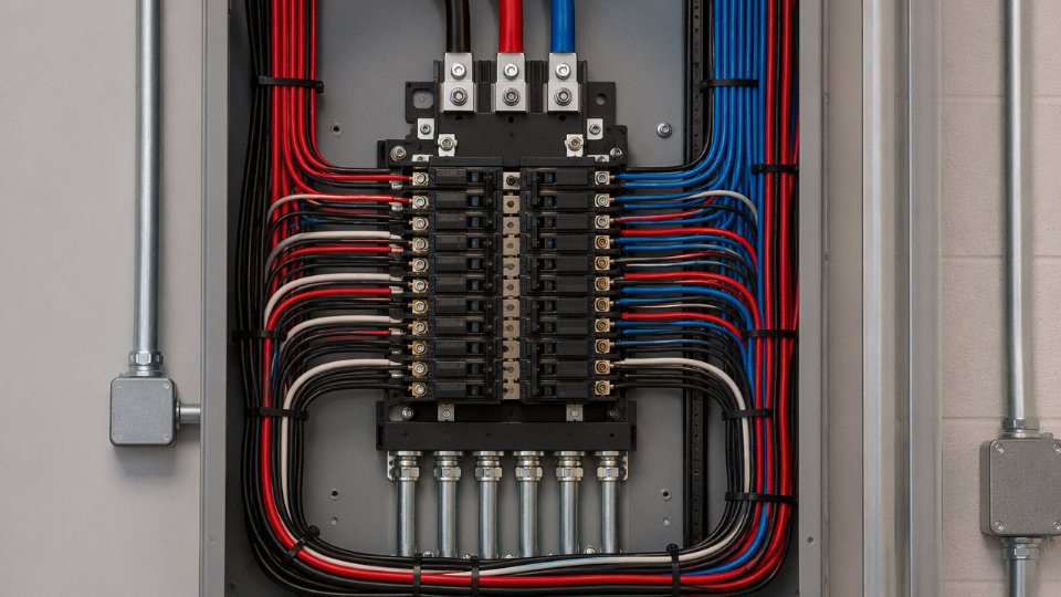
When multiple current-carrying conductors share a conduit or cable bundle, they trap each other’s heat. NEC Table 310.15(C)(1) applies derating factors: three current-carrying conductors run at 100% of rated ampacity, four to six drop to 80%, seven to nine drop to 70%. In practice, this bites hardest on daisy-chained outlet circuits where someone has crammed a dozen conductors into a single conduit run to save on conduit cost. A circuit that looked fine on paper — 12 AWG on a 20-amp breaker — can be undersized in service once the bundle factor is applied. The ground wire counts toward fill but not toward the current-carrying conductor count for derating purposes, which is one of those NEC distinctions that trips up even experienced electricians.
Voltage Drop: The Length Problem
Ampacity gets all the attention, but on longer runs, voltage drop is often the binding constraint. The NEC’s informational note in 210.19(A) recommends limiting branch circuit voltage drop to 3%, with a combined feeder-plus-branch-circuit limit of 5%. These are recommendations, not hard code requirements — but any engineer who ignores them will hear about it from the equipment vendor when the warranty claim comes in.
The math is straightforward. Take a 20-amp, 120 V circuit wired in 12 AWG copper. Resistance for 12 AWG is roughly 1.98 ohms per 1,000 feet. A 50-foot run means 100 feet of round-trip conductor length, giving about 0.198 ohms of total resistance. At full 20-amp load, voltage drop is approximately 3.96 V — right around 3.3% of 120 V. Borderline. Acceptable on a short circuit with modest loading, but if that run stretches to 75 feet or the load is continuous, upsizing to 10 AWG cuts resistance by roughly 37% and brings you back comfortably inside the limit.
Voltage drop in branch circuits is a hard NEC code requirement limited to 3%.False
NEC 210.19(A) informational note recommends 3% as a best practice, but it is not a mandatory enforceable requirement. Many jurisdictions adopt it as standard practice, and equipment warranties may depend on it, but it is technically advisory language in the code.
Why All Three Wires Are Usually the Same Size
In a standard residential or light-commercial branch circuit, hot, neutral, and ground are all the same AWG. This isn’t arbitrary — the neutral must handle the full return current under balanced single-phase loading, and the ground must be capable of carrying enough fault current to trip the overcurrent device before conductors and insulation are damaged. NEC 250.122 allows a reduced ground wire in larger feeder applications, but for branch circuits under 60 amps, the ground is typically the same size as the phase conductors.
The neutral is a different story in facilities with significant nonlinear loads — switching power supplies, LED drivers, variable-speed drives. These generate third-harmonic currents that add in the neutral rather than canceling, meaning the neutral can carry more current than either phase conductor. In those installations, running a full-size or even oversized neutral is not conservative engineering; it’s necessary.
Conductor Tolerance and Why Specifications Matter at the Procurement Stage
This is where the manufacturing side of the conversation becomes directly relevant to anyone buying cable in volume. A conductor specified as 4 mm² nominal might measure anywhere from 3.9 mm² to over 4.1 mm² depending on the manufacturer’s process control. That variance changes actual resistance — and thus both ampacity and voltage drop performance in service. Premium cables built to IEC 60228 Class 1 (solid conductor) or Class 2 (stranded conductor) standards hold cross-sectional area to tighter tolerances, typically within ±1% of nominal. Specifying by conductor class rather than nominal size alone gives you a defensible resistance ceiling and removes ambiguity in cross-border procurement where “12 AWG equivalent” might mean different things to different suppliers.
Cable Types That House All Three Wires: NM-B, AC, MC, and International Equivalents for Outlet Wiring
Walk through any North American residential job site and you’ll see rolls of NM-B cable stacked near the panel rough-in — flat, gray-jacketed, stamped with something like “12/2 WG” or “14/3.” This is the workhorse. Non-metallic sheathed cable bundles the hot, neutral, and bare copper ground together inside a thermoplastic outer jacket, rated 600 V with a conductor temperature rating of either 60°C or 90°C depending on the specific product. NEC Article 334 permits it in dry, interior locations within wood-framed construction — and that covers the vast majority of houses built in the United States and Canada. It’s cheap, fast to install, and every electrician knows it cold. The tradeoff is that the jacket offers essentially no mechanical protection; run it through an exposed basement or a commercial corridor and it’s the wrong tool.
Armored and Metal-Clad Cable: When You Need More Protection
AC cable (Type AC, sometimes called BX colloquially, though that’s a brand name that stuck) wraps an interlocked aluminum spiral armor around the conductors. The ground path in AC cable runs through that armor plus an internal aluminum bonding strip — not a dedicated copper ground conductor. It works, but the armor-as-ground-path approach has a higher impedance than a solid copper ground wire, and any loosened connector at a box can compromise continuity. MC cable solves this by including a fully insulated green or bare copper ground conductor inside the armor. The difference matters: most commercial and industrial specs require MC specifically because the grounding reliability is cleaner and easier to verify with a meter. Both types are approved in locations where NM-B isn’t — unfinished spaces, some exposed runs, plenum applications with the right jacket rating.
Conduit Systems: THHN/THWN Individual Conductors
In light commercial construction, and in any residential project where future flexibility matters, the electrician pulls individual THHN or THWN conductors through EMT (thin-wall steel conduit) or Schedule 40/80 PVC conduit. Each wire — black hot, white neutral, green ground — is a separate conductor. The conduit itself, if metallic, may serve as an equipment ground when properly bonded, though adding a dedicated green conductor is increasingly common practice regardless. Ampacity runs slightly higher than NM-B in equivalent gauges because individual conductors dissipate heat more effectively. More practically, if a circuit needs to be reconfigured five years later, you pull the old wire and fish new conductors without tearing out walls. For wet or exposed locations — an outdoor outlet, a mechanical room, anywhere with spray or condensation — PVC conduit with THWN-2 rated conductors is the correct choice. THWN-2 is rated for 90°C in wet conditions; don’t substitute THHN thinking it’s equivalent in a damp location.
International Cable Assemblies
Outside North America the construction changes, though the three-conductor principle stays identical. UK twin-and-earth cable runs a flat gray PVC sheath over two insulated conductors (brown live, blue neutral) plus a bare copper earth wire sitting between them — the bare earth typically gets sleeved with green-yellow tape at termination points, which is a code requirement under BS 7671 that gets skipped more often than it should on rushed jobs. Australian flat TPS (thermoplastic-sheathed) cable follows a nearly identical physical format, though color conventions differ by era: older installations used red for active and black for neutral, while post-2000 practice shifted toward brown active and blue neutral in line with IEC harmonization.
For flexible connections — appliance leads, pendant drops, movable equipment — European H05VV-F and H07RN-F cables carry the three conductors in a round, flexible assembly. H07RN-F uses a tough rubber jacket suited for outdoor and industrial environments; H05VV-F is the lighter PVC version for indoor appliances. The green-yellow earth conductor runs through both.
Low-Smoke Zero-Halogen Construction
LSZH (low-smoke zero-halogen) cable is worth understanding separately because specifiers in the Middle East, Europe, and Southeast Asia increasingly mandate it for public buildings, transport infrastructure, and marine installations. Standard PVC insulation, when burning, releases hydrogen chloride and other halogenated gases that are acutely toxic and severely impede evacuation. LSZH compounds — typically based on polyolefin or EVA blends — meet EN 50525 and IEC 60332 fire performance requirements by limiting both flame propagation and toxic smoke emission. The cable looks similar externally but costs roughly 20–40% more than PVC-insulated equivalents, depending on conductor count and jacket wall thickness. It’s not over-engineering; in a tunnel or a hospital corridor, the smoke density difference in the first three minutes of a fire is the difference between people finding exits and not finding them.
LSZH cable produces significantly less toxic smoke than standard PVC cable in fire conditionsTrue
LSZH (low-smoke zero-halogen) compounds are formulated to limit halogen acid gas emission and smoke density. This is verified by standardized fire tests including IEC 60754-1/2 (halogen content) and IEC 61034 (smoke density), which are the basis for compliance with EN 50525 and related standards.
Jinda’s Multi-Conductor Building Wire and Export Applications
Jinda manufactures multi-conductor building wire and power cables across this range — XLPE-insulated, PVC-insulated, and LSZH variants — built to IEC, GB, and customer-specified standards. Export production runs covering construction projects in the Middle East, Southeast Asia, Africa, and parts of Europe have required exactly this kind of specification flexibility: a Gulf infrastructure project may call for LSZH-jacketed multi-core cable to IEC 60502, while a Southeast Asian residential development might spec PVC/PVC to a national standard that mirrors IEC closely but with local amendments. The ability to switch insulation systems and qualify to multiple standards within a single production infrastructure is what keeps lead times manageable on large-quantity orders — something a buyer learns to ask about early rather than discovering it mid-project.
Common Wiring Mistakes at Outlets and How Correct Three-Wire Installation Prevents Them
Most outlet failures don’t announce themselves. The outlet works, the lamp turns on, nothing trips — and the hazard sits inside the wall or behind the receptacle face for years. Understanding what each of the three conductors actually does makes these failure modes obvious rather than mysterious.
Reversed Hot and Neutral
Swapping the black and white wires at the outlet terminals is probably the most common mistake made during DIY replacements, and it’s deceptively invisible. The outlet tests live, the lamp lights, the phone charges. What’s wrong is that the switch inside a lamp — or the power switch on a table saw, a toaster, any switched load — is now interrupting the neutral instead of the hot. The socket shell and the load side of the switch remain energized at 120 V even when the device is “off.” Change a light bulb with the switch off and you’re touching an energized brass shell. A $10 outlet tester with indicator lights catches this in three seconds. So does a multimeter: measure hot-to-neutral at the outlet face, then hot-to-ground. If they’re significantly different, something is wrong with polarity or grounding. Fix it before energizing the circuit.
Open Ground
An outlet with no ground connection will pass every functional test except the safety one. The receptacle powers loads fine. The problem surfaces when an appliance develops an internal short to its chassis — a drill with a frayed winding, a refrigerator with a pinched compressor lead. Without a low-impedance path to ground, fault current has nowhere to go except through the next person who touches the metal housing. The NEC does allow GFCI protection as a substitute for a physical ground in older two-wire systems under 406.4(D)(2), but that GFCI outlet must be labeled “No Equipment Ground” — a requirement that gets skipped constantly in practice. GFCI substitution protects people; it does not give you an equipment ground for sensitive electronics or EMI-sensitive instrumentation.
Floating Neutral on Multi-Wire Branch Circuits
This one can destroy equipment. In a multi-wire branch circuit sharing a neutral between two 120 V legs, the neutral carries the difference current between the two legs and keeps each leg at roughly 120 V relative to ground. If that shared neutral goes open — a loose wire-nut, a corroded terminal, a backstab connector that vibrated loose over years of thermal cycling — the 240 V across both legs doesn’t disappear. It redistributes according to load resistance. A high-resistance load like a lamp can see 150 V or more while a low-resistance motor on the other leg drops to 70 V and runs hot. Lamps blow, electronics fail, motors overheat. The fix is torqued terminal connections and, on shared neutrals, a handle-tied breaker so both legs go dead together during service.
Mismatched Wire Gauge and Breaker Rating
14 AWG copper wire is rated for 15-amp continuous service under NEC 310.15, not 20 amps.True
NEC Table 310.15(B)(16) assigns 14 AWG copper a 15-amp ampacity under standard installation conditions. Installing it on a 20-amp breaker allows the overcurrent device to pass up to 20 amps through a conductor not rated for that load.
Installing 14 AWG wire on a 20-amp breaker is a code violation with a real thermal consequence. At sustained 20 A, a 14 AWG conductor runs hot enough to soften thermoplastic insulation — gradually, over months. Insulation that has softened and re-hardened loses its rated dielectric properties. Eventually it cracks at bends, contacts the jacket or adjacent conductors, and ignites. Match wire gauge to breaker rating. That’s not a preference; it’s NEC 240.4(D).
Bootleg Ground
A bootleg ground is a jumper wire connecting the ground terminal to the neutral terminal at the outlet itself. It makes an outlet tester show “correct” on all three indicators. It is not a ground. It puts neutral current — which in any real circuit is nonzero — onto the ground conductor and onto the chassis of every appliance connected through it. There have been electrocutions traced to this exact configuration. A clamp meter around the ground prong wire will show measurable current if a bootleg ground is present; a true equipment ground carries essentially zero current under normal conditions. If you’re inspecting outlets in a house that was “updated” by unknown hands, test for this specifically.
Why Cable Construction Affects Field Termination Quality
Even correct wiring practice can be undermined by poor cable. Insulation that doesn’t bond adequately to the conductor tends to pull back from cut ends during stripping, leaving exposed conductor beyond the terminal — a contact fault waiting to happen. Jinda cables go through conductor-to-insulation adhesion testing and jacket integrity verification during production specifically so that when a technician strips and terminates the wire, the insulation stays where it belongs. It sounds like a minor detail until you’ve seen a backstab terminal arc against a conductor that migrated 4 mm out of position inside a finished wall.
Most of these mistakes are caught by inspection, proper testing after installation, and using the right cable from the start. None of them require exotic tools or training — just knowing what each of the three wires is supposed to do and verifying it did.
Frequently Asked Questions About the Three Wires in an Outlet
Can I connect an outlet with only two wires (no ground)?
Yes, and this comes up constantly in older homes wired before grounding became standard. NEC 406.4(D)(2) allows you to replace an ungrounded two-wire outlet with a GFCI receptacle, provided you label it “No Equipment Ground.” The GFCI will trip on a ground-fault current imbalance between hot and neutral — that’s genuine shock protection. What it won’t do is give sensitive electronics a low-impedance path to dissipate surge energy. If you’re running a workstation or medical equipment off that circuit, consider running a proper ground back to the panel or installing a separate surge suppressor. The label requirement isn’t optional; inspectors look for it.
What happens if I mix up the hot and neutral wires at the outlet?
The outlet will power a lamp or a phone charger just fine, which is exactly why this mistake gets missed. The real problem: with reversed polarity, the shell of a lamp socket sits at line voltage, and the load side of a switched device stays energized even when its switch is off. Someone changing a bulb with the switch off can still get a shock. Always check polarity with a non-contact voltage tester — or a simple plug-in polarity tester, roughly $5–10, before you close up the box.
A reversed hot and neutral wire will still power most devices normallyTrue
Alternating current completes the circuit regardless of which terminal the hot connects to, but it leaves exposed parts of the device energized and creates a legitimate shock hazard.
Why is the ground wire sometimes bare copper and sometimes green?
Bare copper is permitted inside cable assemblies and conduit where the cable jacket or conduit itself provides physical protection. When a ground conductor runs loose in a conduit alongside insulated phase conductors, it needs visual identification — that’s where green insulation comes in. Outside North America, IEC standards specify green-yellow stripe as the earth conductor, which is worth remembering on any cross-border project. A solid green conductor, a bare copper conductor, and a green-yellow striped conductor all serve the same protective function; the difference is purely about where they’re installed and which standard governs.
Do all three wires need to be the same gauge?
On a standard residential branch circuit — 14 AWG on a 15-amp circuit, 12 AWG on a 20-amp circuit — the hot, neutral, and ground are typically the same size. NEC 250.122 does allow a reduced ground conductor on larger feeder circuits, sized to the overcurrent device rather than matching the phase conductors. In industrial three-phase distribution with balanced loads, you’ll sometimes see a reduced neutral, since the phase currents cancel and the neutral carries only the residual unbalance. For branch circuits feeding outlets, don’t get creative — match the gauge across all three conductors.
What is the difference between the neutral and ground if both land on the neutral bar in the panel?
They share the neutral bus at the main service panel because that’s where the neutral-ground bond is intentionally made — one point, and only one point. The neutral carries return current on every normal operating cycle. The ground carries current only during a fault. Downstream in a sub-panel, they must be separated onto isolated bars. If you bond them again in a sub-panel, neutral return current starts flowing on grounding conductors and metal enclosures — you’ll have voltage on surfaces that are supposed to be at zero potential. That’s a code violation and a real hazard, not a theoretical one.
How do I know what wire gauge is already installed in my wall?
The outer jacket of any NEC-compliant cable is printed with the relevant data — conductor count, gauge, voltage rating, temperature rating. A typical marking reads something like 12/2 WITH GROUND NM-B 600V 90°C. That tells you everything you need before touching the circuit. If the jacket is painted over, charred, or the print has worn off (common in older construction), use a wire gauge tool directly on the bare conductor tip inside the outlet box. Don’t guess; an undersized circuit fed by a larger breaker is how overloads turn into fires.
Are the three wires in a standard outlet the same internationally?
The electrical function is universal — live, neutral, and earth, every time. Everything else varies: wire colors, pin geometry, voltage level (120 V in North America, 220–240 V across most of Europe, Asia, and Australia), frequency, and the governing standard. An installer moving from NEC work to a BS 7671 project in the UK needs to know that brown is now live, blue is neutral, and green-yellow is earth — what was previously a neutral color in the US is now live in a UK installation. Always verify cable markings against the applicable national standard before energizing anything on an international project. Color assumptions get people hurt.
Sourcing Three-Conductor Outlet Cables for Large-Scale Projects: What to Specify and What to Verify
Buying cable for a single outlet replacement and buying cable for a 500-unit residential development are entirely different problems. The electrical function of the three conductors doesn’t change, but the procurement risk scales dramatically — and the consequences of a bad specification or a substituted material show up after the walls are closed.
Write a Complete Technical Specification Before You Issue an RFQ
A purchase order that says “3-core 2.5 mm² cable, 100 drums” will get you something. Whether it’s the right something is another matter entirely.
A minimum workable specification should state: conductor material (electrolytic tough-pitch copper per IEC 60228 — more on why that phrase matters shortly), conductor class (solid Class 1 for fixed residential runs, stranded Class 2 where flex or repeated movement is involved), nominal cross-sectional area in mm² or AWG depending on your governing standard, number of cores including ground, insulation material and assigned color code for each core matched to the target country standard, outer jacket material (PVC, LSZH, or armored as the installation demands), voltage rating (typically 300/500 V or 450/750 V for outlet circuits), temperature rating (60°C, 75°C, or 90°C at the conductor), and the specific standard the cable must conform to — NEC/UL, IEC 60227/60245, GB/T 5023, BS 6004, or AS/NZS 5000 depending on destination.
Skipping any of these items leaves room for a supplier to make a substitution that is technically defensible on their end and genuinely problematic on yours.
Certifications and Test Reports Worth Asking For
For North American projects, UL listing on the cable construction is effectively non-negotiable on any job that will see an inspection. EU-destined product needs a CE declaration of conformity backed by a real test report, not just a self-declaration stamp. China domestic projects require CCC certification. Australia requires SAA/RCM marking per AS/NZS 5000.
Beyond the marks themselves, request the actual test reports: conductor DC resistance per IEC 60228, insulation resistance (usually expressed as MΩ·km at a specified voltage and temperature), voltage withstand (both spark test during production and a sample high-voltage soak), and if you’ve specified LSZH jacket, smoke density and flame propagation results to IEC 61034 and IEC 60332-3 respectively. A legitimate manufacturer has these on file. If the response to that request is vague, that tells you something.
Conductor Resistance as a Quality Screen
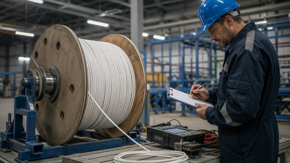
This is the practical check that catches the most common forms of cable adulteration. IEC 60228 sets maximum DC resistance values at 20°C for each conductor class and cross-section — a 4 mm² Class 2 copper conductor must not exceed 4.95 Ω/km, for instance. The drum test certificate should show the actual measured value for every drum in the order. Values sitting suspiciously close to the maximum limit, or inconsistent across drums from the same production batch, are worth investigating before you unroll anything.
The CCA Problem Is Real and Still Common
Copper-clad aluminum conductors have a conductivity roughly 60% of solid copper. A cable that physically measures 2.5 mm² in cross-section but is wound from CCA instead of copper will run hotter under load, produce higher voltage drop over long runs, and in worst cases be a fire risk in high-current applications. The insulation color looks identical. The drum marking often says “copper conductor.” The only reliable protection is specifying “electrolytic tough-pitch copper per IEC 60228” explicitly in your purchase order and requesting a material certification — a mill certificate or third-party XRF test on a sample from the delivered reel.
Copper-clad aluminum (CCA) cable marketed as copper has approximately 60% of copper's conductivity, reducing ampacity and increasing voltage drop for a given conductor cross-section.True
CCA conductors consist of an aluminum core with a thin copper cladding. Aluminum's conductivity is roughly 3.5 × 10⁷ S/m versus copper's ~5.8 × 10⁷ S/m, giving CCA approximately 61% of copper's conductivity when the cross-section is primarily aluminum. This directly reduces current-carrying capacity and increases resistive losses.
Receiving Inspection on a Large Order
Don’t skip this step because the paperwork looked clean. On arrival, check drum markings against every field on your purchase order — standard, voltage rating, cross-section, color codes, length. Measure conductor resistance on a sample of drums with a calibrated micro-ohmmeter; this takes roughly ten minutes per drum and will catch CCA substitution and undersized conductors. Physically inspect the insulation color sequence — a swap between neutral blue and ground green-yellow has caused serious installation errors on international projects where the crew was used to a different convention. Spot-check jacket thickness with a caliper against the specification value. Verify the printed length counter on the outer jacket against an independent measurement on at least one drum per lot; short drums on large orders represent a direct material loss that adds up fast.
Why Jinda Is a Practical Option for This Kind of Procurement
With five production bases across China, 470,000 m² of manufacturing floor space, and an integrated QC and R&D setup that supports production to NEC, IEC, GB, and customer-specified standards simultaneously, Shandong Jinda Special Cable Group can issue full test documentation — drum certificates, third-party reports, material certifications — as standard rather than on request. Their supply experience across 50-plus countries means the specification and color-code conversations for projects going to the US, Europe, Australia, or the Middle East are not new territory. For procurement managers running a project that needs consistent quality across multiple shipments over an extended timeline, that kind of integrated capability and documented track record matters more than a low unit price on a single trial order.