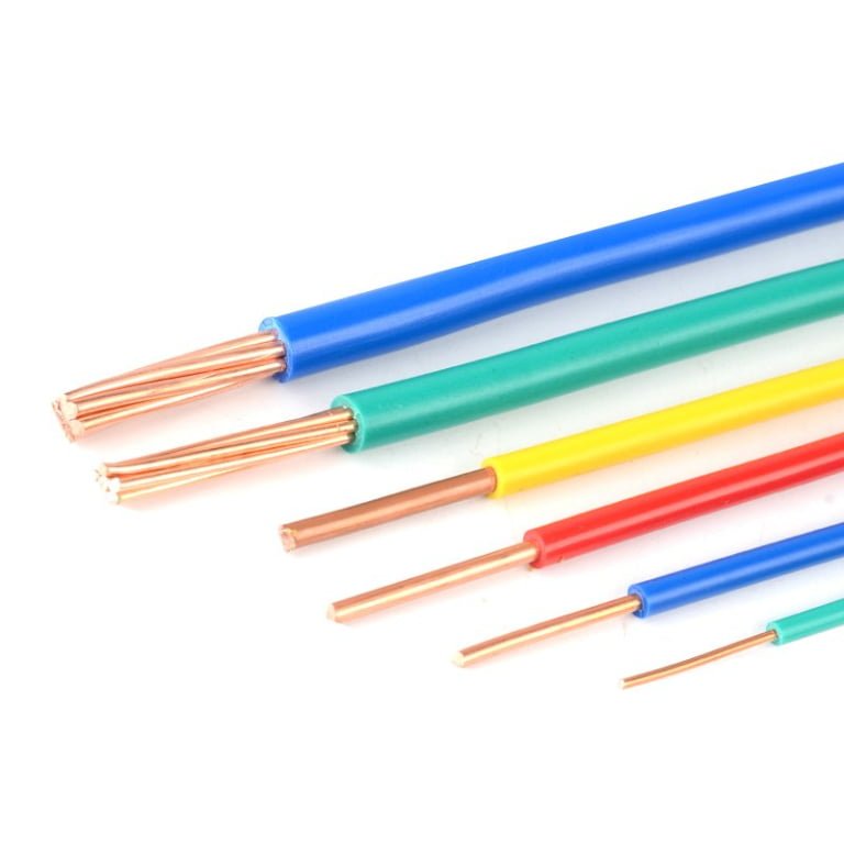
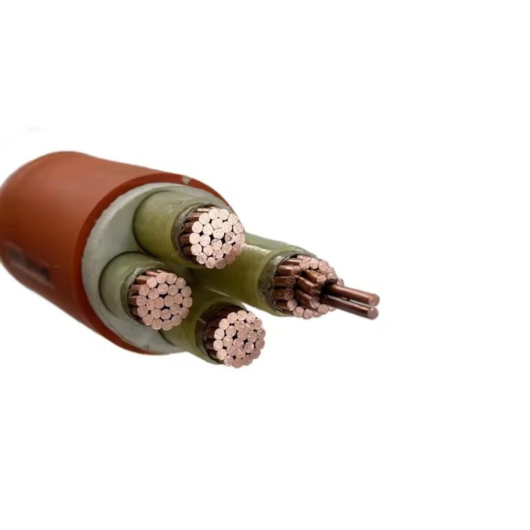
Pulling an unlabeled cable from a tray and guessing its type is one of those habits that looks harmless until it isn’t. Wrong identification leads to mismatched terminations, breaker trips on first energization, insulation failure under actual service voltage, or — in armored cable runs — a grounding path that doesn’t actually exist. The downstream cost isn’t just a failed inspection; it’s unplanned downtime, rework labor, potential equipment damage, and in some jurisdictions a mandatory re-test of the entire installation.
To identify an electrical cable type, read the print legend on the outer jacket for voltage rating, standard designation, conductor count, and cross-section; check insulation and jacket color against the regional code (NEC, IEC, or GB); measure conductor diameter to confirm AWG or mm² size; inspect armor type (SWA, STA, or none); and match all markings against the relevant standard — UL, IEC 60502, BS 6346, or DIN VDE — to confirm the full specification.
What makes this genuinely tricky in practice is that the same physical cable can be compliant under three different standards, marked in two languages, and still be the wrong choice for your specific installation — because voltage class, flame rating, and armor configuration are all independent variables that have to be confirmed separately. The sections below work through each identification method in the order a plant engineer would actually use them on a real cable drum.
Reading the Cable Print Legend: Decoding Manufacturer Markings and Standards Stamps
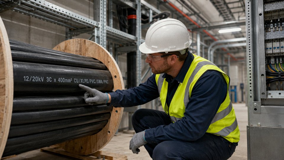
Every cable that leaves a reputable factory carries its entire identity on its outer jacket. Learn to read that print legend properly and you can confirm voltage class, conductor size, insulation type, and applicable standard without unwrapping a single layer — a significant advantage when you’re commissioning a panel in a hurry or receiving a partial drum from a third-party distributor.
Anatomy of a Standard Print Legend
A well-printed jacket legend typically runs sequentially: manufacturer name or trademark, cable type designation, voltage rating, core configuration, and year of manufacture — sometimes a sequential footage or meter counter as well. A typical line might read something like:
JINDA NYY-J 0.6/1 kV 4×95 mm² IEC 60502-1 2023
Each field is load-bearing. “NYY-J” tells you PVC insulation over PVC sheath, with the “-J” suffix indicating the green-yellow PE conductor is present (per DIN VDE 0276). Drop that suffix and you have NYY without a dedicated earth core — a meaningful difference on any installation following German or Central European practice. The voltage rating “0.6/1 kV” means 0.6 kV phase-to-earth, 1 kV phase-to-phase; misreading this as a 1 kV absolute rating has caused protection coordination problems on more than one site. “4×95 mm²” tells you four conductors, each 95 mm² cross-section — don’t assume they’re all the same insulation color without checking the core identification table in the cable’s data sheet.
Year of manufacture matters more than people expect. Plasticizer migration in older PVC sheaths, UV degradation in outdoor-rated cables, and changes to compound standards over time all make a 2009 drum and a 2023 drum of nominally the same cable subtly different animals, especially if you’re replenishing a partial installation.
North American Markings: UL Listings and NEC Type Codes
North American cables follow a different logic. A THHN conductor jacket might read: 12 AWG THHN 600V (UL) 90°C MTW/THWN-2. Each segment earns its place. “THHN” is the NEC type code — thermoplastic high heat-resistant nylon-coated. The “90°C” rating applies in dry locations; if the same conductor carries a “THWN-2” dual listing, it’s also rated for 90°C in wet conditions, which changes your ampacity calculation under NEC 310. The UL mark confirms third-party listing, not just manufacturer self-declaration.
AWG sizing runs inverse to intuition: AWG 4/0 (often written 0000) is the largest at roughly 107 mm², while AWG 28 is a fine instrument wire at around 0.08 mm². Cables for direct burial or service entrance will carry type codes like USE-2 or RHH/RHW-2, each with specific allowable wiring methods. MC cable per UL 1569 carries an interlocked armor and will have the MC designation printed on the outer armor wrap or jacket, not always on the individual conductors inside — worth checking both surfaces.
IEC, European, and CENELEC Harmonized Codes
European harmonized cables use a structured CENELEC code. “H05VV-F” breaks down as: H = harmonized, 05 = 300/500 V, V = PVC insulation, V = PVC sheath, F = flexible (fine-wire) conductor. “H07RN-F” is 450/750 V with rubber insulation and rubber sheath, flexible — the classic heavy workshop trailing lead. National prefix variations exist; a “Y” prefix instead of “H” indicates a nationally approved cable rather than a fully harmonized type, which can matter for cross-border project compliance.
DIN VDE type codes like NYCWY or NHXMH follow German nomenclature rules with consistent character positions. Halogen-free compound cables, increasingly specified in tunnels and public buildings, often carry LSZH or NHXH designations. If your project specification calls for LSZH and the delivered drum reads NYY, that’s not a minor substitution — it’s a material nonconformance.
Chinese GB Standard Markings and Bilingual Export Legends
China’s GB standard uses a parallel letter-code system. A typical designation like ZR-YJV22 means: ZR = flame retardant, YJ = XLPE insulation, V = PVC sheath, 22 = double steel tape armor. Phase color sequence under GB/T follows yellow (A), green (B), red (C), blue for neutral, and green-yellow for PE — which differs from both IEC brown/black/grey and NEC black/red/blue. On a mixed international jobsite, that mismatch creates real termination risk if the installer defaults to their home-market color assumptions.
Jinda prints bilingual English and Chinese legends on cables produced for export projects, so international contractors and third-party inspectors can verify cable specifications without translation support.True
Bilingual cable marking is a documented export practice at Jinda, intended to reduce specification ambiguity on international jobsites where Chinese-only markings may not be legible to local installation teams or third-party inspectors.
For export runs, Jinda prints the full IEC designation alongside the GB code, the rated voltage in both formats, and English core-count notation. In practice this makes receiving inspection faster and reduces the chance of a cable being set aside as “unverified” during a third-party audit.
When the Legend Is Gone
Outdoor cables installed years ago, cables pulled through abrasive conduit, or anything recovered from a demolition site may have no legible print at all. Start with the sequential footage markers — most quality manufacturers print meter or foot counts every 300–600 mm, and even a partial number helps you confirm you’re reading the same drum you thought you were. A cable identifier or toner can confirm continuity and routing without energizing.
If you genuinely cannot establish cable type from visual inspection, escalate to physical testing: conductor resistance measurement to back-calculate cross-section, high-pot testing to bracket voltage class, or in critical applications, a sample sent to a testing lab for insulation compound analysis. Don’t guess on a 6/10 kV circuit because the jacket looks like it might be medium-voltage.
One zero-cost habit worth adopting: photograph the cable print legend before the cable goes into conduit or trench. Thirty seconds with a phone camera creates a permanent record tied to a location, saving real diagnostic time two or three years later when someone needs to know what’s actually in that duct.
Color Code Systems by Region and How to Interpret Core Insulation Colors
Color coding is the fastest identification shortcut on any job site — but it’s also one of the most dangerous shortcuts if you treat it as gospel. Standards differ by country, legacy wiring doesn’t always match current codes, and in older industrial facilities the colors can be so faded or discolored by heat that you’re essentially guessing. Use color as the first filter, never the only one.
US NEC Conventions
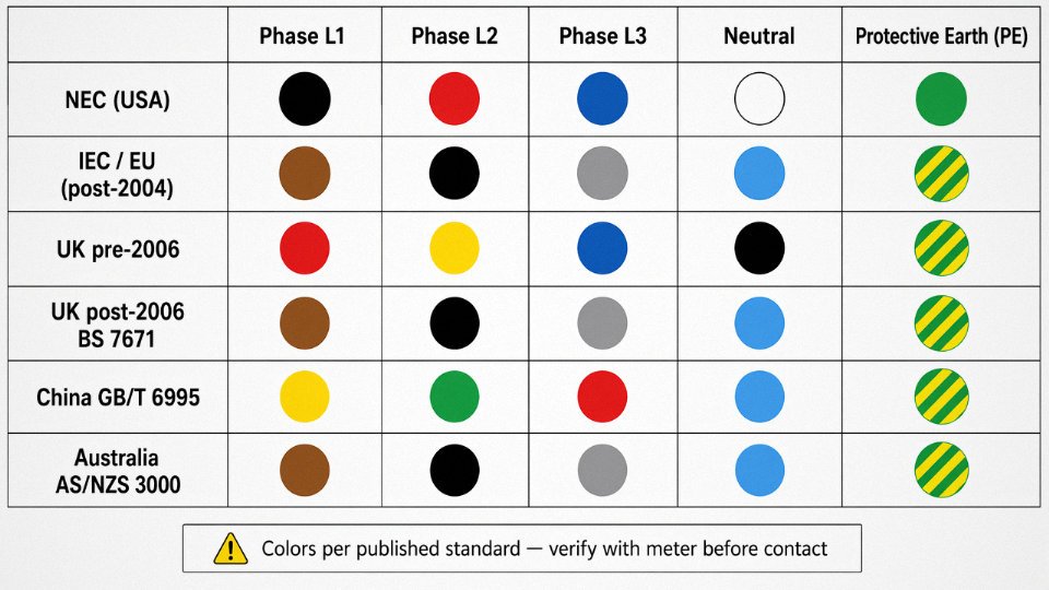
Under NFPA 70 (NEC), the ungrounded phase conductors are black, red, and blue for phases A, B, and C respectively in a three-phase system. White or grey is reserved for the neutral (grounded conductor), and green or bare copper is the equipment grounding conductor. In practice, installers in the US sometimes use other colors for phase conductors in conduit runs — the NEC permits any color except white, grey, or green for ungrounded conductors — which means you can encounter orange, yellow, or even brown phase wires in older commercial panels. That’s legal, but it makes life harder during maintenance. Always verify with a meter before touching anything in an unfamiliar US panel.
IEC/EU Harmonized Colors
IEC 60446 (now absorbed into IEC 60445) standardized three-phase colors across Europe: brown, black, and grey for L1, L2, and L3; blue for neutral; green-yellow bicolor for protective earth (PE). The 2004 harmonization update was significant because it aligned most EU member states onto a single scheme, but it also created a cut-off point. Cables installed before roughly 2004–2006 in many countries may follow the older national standards — red, yellow, blue for phases, black for neutral, green-yellow for earth in Germany, for instance — so in any European industrial plant that predates the mid-2000s, assume the wiring could be either system.
UK: Old Colours vs. Post-2006 BS 7671
This is where confusion genuinely causes incidents. Pre-2006 UK wiring uses red for live, black for neutral, and green-yellow for earth in single-phase; three-phase was red, yellow, blue for phases, black for neutral. After the 17th Edition of BS 7671 came into force, UK adopted the IEC harmonized scheme: brown for live, blue for neutral, green-yellow for earth — identical to IEC/EU. The problem is that both systems coexist in UK buildings right now, sometimes on opposite ends of the same circuit in a partial rewire. A black conductor in pre-2006 UK wiring is a neutral; a black conductor in a new IEC-compliant circuit is a phase. Getting those confused is a serious hazard.
China GB 7947
China’s GB/T 6995 standard specifies yellow, green, and red for phases A, B, and C; light blue for neutral (N); and green-yellow bicolor for PE. This is broadly similar to older European practice, which occasionally causes confusion when cables sourced from China arrive on an EU jobsite. For export projects, cables from manufacturers like Jinda are produced to the destination country standard — a shipment going to a German contractor gets IEC-harmonized core colors, not GB colors. Worth confirming on your purchase order rather than assuming.
Cable manufacturers producing for export routinely reconfigure core insulation colors to comply with the destination country's standardTrue
Major cable standards (IEC 60446, NEC, BS 7671, GB/T 6995) each mandate specific core colors; a compliant cable for Germany requires brown/black/grey/blue/green-yellow, which differs from the Chinese GB standard of yellow/green/red/light-blue/green-yellow. Reputable export manufacturers apply the correct scheme at the extrusion stage.
Australia AS/NZS 3000
Worth mentioning because Australian installations are common in Pacific export projects. Post-2000 AS/NZS 3000 uses red, white, and blue for phases; black for neutral; green-yellow for earth in three-phase systems. That white phase conductor catches people off guard — in NEC territory, white means neutral.
Color Code Comparison Table
| Conductor | US NEC | IEC / EU | UK Pre-2006 | UK Post-2006 | China GB | Australia AS/NZS |
|---|---|---|---|---|---|---|
| Phase A / L1 | Black | Brown | Red | Brown | Yellow | Red |
| Phase B / L2 | Red | Black | Yellow | Black | Green | White |
| Phase C / L3 | Blue | Grey | Blue | Grey | Red | Blue |
| Neutral (N) | White / Grey | Blue | Black | Blue | Light Blue | Black |
| Earth / PE | Green / Bare | Green-Yellow | Green-Yellow | Green-Yellow | Green-Yellow | Green-Yellow |
Numbered Core Cables and the Limits of Color
Once you get beyond five cores — instrument cables, control cables, multicore signal cables with 12, 19, or 37 pairs — the color system runs out of usable distinctions. The industry solution is numbered cores: each conductor carries a printed or embossed number, usually starting at 1, with core 1 sometimes colored differently to establish polarity or reference. IEC 60228 and manufacturer-specific standards govern this. On the plant floor, you read numbered cores with a continuity tracer or by following the printed schedule in the cable tray manifest, not by color alone.
The broader limitation is worth stating plainly: color alone is never sufficient for positive cable identification in any industrial or multi-tenant setting. Colors fade under UV exposure and prolonged heat — PVC insulation that started life as a bright green-yellow PE conductor can look yellowish-brown after fifteen years near a furnace. Non-compliant legacy installations exist everywhere. Treat core color as supporting evidence, not proof, and confirm conductor function with proper test equipment before any work begins.
Physical and Structural Inspection: Identifying Cable Construction Layers by Touch and Visual Examination
Before you cut into anything, stop. An unknown cable could be live, could be rated for a voltage class you didn’t expect, or could contain insulation that releases toxic fumes when nicked. The physical inspection process starts with procedure, not curiosity.
Safe Stripping Procedure
Always verify the circuit is de-energized with a calibrated non-contact voltage tester — two independent measurements, not one. Lock out and tag out. Wear cut-resistant gloves rated to EN 388 or ANSI A4 at minimum; standard rubber electrical gloves alone won’t protect against a slipping knife. Use a purpose-made cable stripper with adjustable blade depth rather than a utility knife. Setting the blade depth incorrectly is one of the more common ways inspectors nick conductor strands, which effectively deretes the conductor — a 16 mm² cable with 12 damaged strands no longer carries like a 16 mm² cable. If you’re inspecting a cable that’s already been terminated, leave it in circuit as long as possible and only strip a short test section from a cut end or a dedicated sample length.
Reading Insulation by Appearance and Feel
PVC insulation is glossy, moderately stiff when cold (noticeably stiffer in winter in unheated plants — worth remembering), and has a faint chemical smell, especially on freshly cut ends. XLPE runs firmer, usually off-white or solid black, and doesn’t have much smell at all. The surface is slightly duller than PVC. EPR is the rubbery one — it compresses easily under finger pressure and springs back, often with a slightly tacky surface. PTFE is unmistakable: bright white, very stiff, almost slippery to the touch, and it resists deformation in a way no other common insulation does. Silicone is soft and matte-finished, almost like compressed foam rubber, and it tolerates being bent sharply without cracking — you’ll find it in furnace wiring and high-temperature sensor leads. In practice, PVC and XLPE get confused most often because both can appear black on power cables; firmness and cross-section color after cutting (XLPE stays uniform off-white or black through the cut face) usually settles it.
Shielding Layers
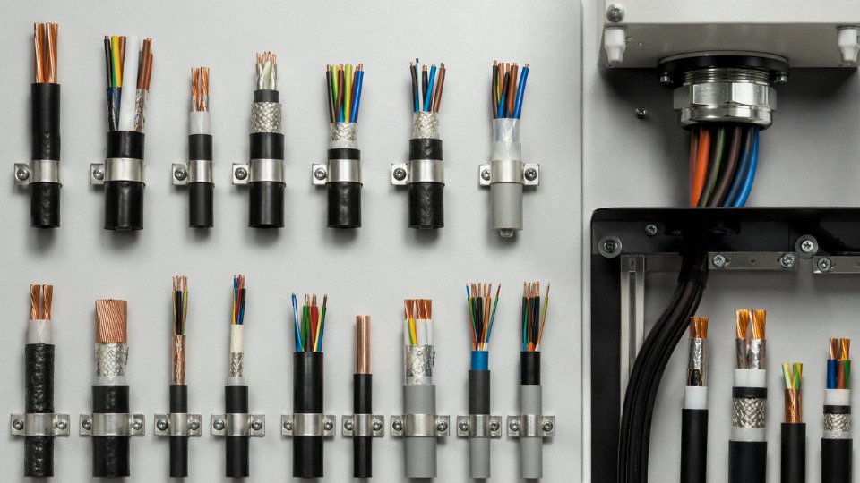
Peel back the outer jacket and look for a metallic layer sitting between the jacket and the core insulations. Aluminum foil tape appears as a flat, continuous metallic film — often with a thin polyester backing bonded to it. Copper braid shield is immediately obvious: woven copper strands, usually bright or slightly tarnished, that you can flex and fray with a fingernail. Instrumentation cables frequently run a foil shield plus a small-gauge drain wire (typically 24 AWG to 20 AWG, bare or tinned copper) lying alongside the foil — the drain wire gives you a termination point without puncturing the foil itself. If you see both a braid and a foil layer, you’re looking at a high-interference-rejection cable probably spec’d for signal or data service in a noisy industrial environment.
Armor Identification
Steel wire armor (SWA) is a layer of round steel wires wound helically — you can feel each individual wire and measure them with a caliper. Typical wire diameters run 1.6 mm to 4.0 mm depending on cable diameter and application. Steel tape armor (STA) uses flat overlapping steel strip rather than round wires; it’s less flexible and more common in fixed installations where crushing resistance matters more than bend radius. Aluminum wire armor (AWA) looks similar to SWA but is lighter and non-magnetic — relevant when you’re running cables through or near equipment sensitive to induced magnetic fields, such as certain metering or transformer installations. In North American plants, interlocked armor (the MC cable construction per UL 1569) has a distinctive spiral-interlocked aluminum or steel strip that rattles slightly and feels segmented rather than smooth.
Aluminum wire armor (AWA) produces significantly less induced current heating in single-core AC cable installations compared to steel wire armor (SWA).True
Steel armor on single-core AC cables creates a closed magnetic path that induces circulating currents and increases losses. AWA, being non-ferromagnetic, avoids this and is standard practice for single-core medium-voltage cables per IEC 60502-2.
Counting Cores and Estimating Conductor Cross-Section
Count the insulated cores first, then look for a separate earth or drain conductor. A digital caliper on a stripped, uncompressed conductor bundle gives you an outer diameter; from there, cross-section roughly follows πr² but stranded conductors compress slightly, so add about 5–8% for a realistic estimate. A quick reference:
| Measured diameter (stranded, mm) | Approximate cross-section |
|---|---|
| ~2.8 mm | 4 mm² / AWG 12 |
| ~4.0 mm | 10 mm² / AWG 8 |
| ~5.7 mm | 16 mm² / AWG 6 |
| ~9.0 mm | 50 mm² / AWG 1/0 |
These are estimates. Don’t use them for a sizing decision without confirming against the print legend or a proper resistance measurement.
Jacket Material
Standard PVC jacket is flexible enough to coil easily and leaves a slight mark when pressed with a fingernail. LSZH (low-smoke zero-halogen) compound is waxy to the touch, less pliable, and often comes in grey or orange — it resists coiling tightly without cracking more than PVC does. Polyurethane jacketing, common on trailing and reeling cables used with mobile equipment, is noticeably tougher and more abrasion-resistant; it snaps back after stretching rather than staying deformed like PVC sometimes does at elevated temperatures.
When Physical Inspection Isn’t Enough
Some situations require more than your eyes and hands. If you need to confirm whether insulation is genuinely XLPE or a filled HDPE compound (some lower-cost cables get misrepresented), a laboratory DSC (differential scanning calorimetry) test on a small sample will settle it. Similarly, if you suspect the armor is lower-grade steel than specified, a hardness test or XRF analyzer on-site gives quick confirmation. For conductor material — copper versus aluminum — a brief resistance measurement per unit length, compared against published values, is faster and more reliable than any visual test. Electrical testing including insulation resistance (IR) and partial discharge testing is necessary before energizing any cable whose voltage class you cannot confirm from markings alone.
Electrical Testing Methods to Confirm Cable Type, Rating, and Insulation Integrity
Visual inspection and jacket markings get you most of the way there, but they don’t get you all the way. A cable with a legible print legend and intact sheath can still have compromised insulation from a previous fault, moisture ingress during outdoor storage, or simply be the wrong construction for the circuit it’s being installed on. Electrical testing closes that gap. These methods are not bureaucratic checkboxes — they tell you whether the cable in your hand is actually fit for the voltage class and environment you’re assigning it to.
Continuity Testing: Verify What’s Actually There
Start with the basics. Before any other test, use a digital multimeter in resistance mode to confirm conductor count and verify no open circuits exist. This sounds obvious, but on multi-core cables — say, a 19-core or 37-core instrumentation cable — it’s easy to miss a broken conductor that was damaged during pulling or termination. Acceptable resistance will vary with conductor cross-section and length; a 2.5 mm² copper conductor running 100 m should read roughly 0.7–0.8 Ω, give or take depending on temperature. A reading several times higher than expected points to a partial break or a wrong cross-section entirely.
Insulation Resistance Testing: The Megohmmeter is Your Best Friend
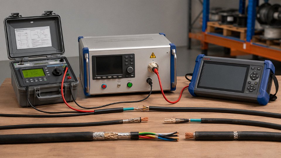
IR testing is where you confirm the insulation class. Use a megohmmeter (commonly called a Megger, though that’s a brand name) and apply the correct test voltage for the cable’s rated class: 250 V DC for 300/500 V light-duty cables, 500 V DC for 0.6/1 kV cables, and 1,000 V DC for medium-voltage cables up to roughly 3.6/6 kV. For higher MV classes, test voltage steps up further — consult IEC 60502-2 or IEEE 400 for the specific voltage class you’re dealing with.
For new cables, IEC 60502 and IEEE 400 both expect insulation resistance values well above 100 MΩ·km at 20°C. In practice, a new, dry, undamaged 0.6/1 kV PVC cable will typically test anywhere from several hundred MΩ to several GΩ depending on length and temperature. A reading below 1 MΩ on what’s supposed to be a new cable is a serious red flag. Most likely causes: moisture inside the jacket from improper drum storage, mechanical damage to the insulation during installation, or — less obviously — the wrong cable type was supplied and the insulation material doesn’t match the specification.
Insulation resistance values decrease significantly as cable temperature rises, so a test result taken at 40°C will read lower than the same cable tested at 20°C — both readings can be normal for the same cable.True
IR values approximately halve for every 10°C rise in temperature for many polymer insulation types. IEEE 400 and IEC 60502 both reference correction factors for temperature normalization.
High-Voltage Withstand (Hipot) Testing
A hipot test applies a voltage significantly above rated to stress the insulation and confirm it won’t fail in service. For a 0.6/1 kV cable, the DC test voltage is typically calculated as 2U₀ + 1,000 V, where U₀ is the conductor-to-earth voltage. AC hipot tends to be more representative of real operating stress but is harder to conduct in the field; DC hipot is far more common for cable commissioning.
A clean pass — stable leakage current, no breakdown — confirms the insulation type and thickness are consistent with the rated voltage class. A failure, or a leakage current that climbs steadily during the test rather than stabilizing, suggests either damaged insulation or a material that doesn’t belong in that voltage class. This is relevant when you’re trying to confirm whether an unmarked cable is genuinely rated for 6/10 kV or has been misidentified.
One operational warning: never conduct IR or hipot tests on a circuit that may be energized elsewhere in the loop. LOTO before connecting any test equipment — this is non-negotiable. After HV testing, cables retain a capacitive charge that must be discharged through a resistive discharge device before anyone touches the conductors. On longer runs or larger cross-sections, that charge can persist for minutes.
TDR and Impedance-Based Identification
Time-domain reflectometry is primarily a fault-location tool, but it’s useful here because the propagation velocity and characteristic impedance of a TDR trace depend on the cable’s construction — conductor cross-section, insulation type, and geometry. If you have a datasheet for a suspected cable type, you can compare the measured impedance profile against the expected value. It won’t give you a definitive identification on its own, but it corroborates other findings. TDR is also the fastest way to confirm total cable length when the drum label is missing or illegible, which happens more often than it should on busy sites.
Capacitance and Inductance Checks for Instrumentation Cables
For coaxial or shielded instrumentation cables, capacitance per unit length is a published construction parameter. Measuring it with an LCR meter and dividing by cable length gives you a figure you can cross-reference against manufacturer datasheets. A 1 mm² screened pair might spec at 100–200 pF/m depending on insulation geometry; a result well outside that range suggests you have a different construction than what’s on the label. This matters for signal integrity on long instrumentation runs, not just voltage ratings.
The broader point: electrical testing is most powerful when you use it as a cross-check against the physical inspection and jacket markings covered in earlier sections. No single method is conclusive alone. A cable that passes IR but has wrong capacitance figures may still be the wrong cable for a control system application. Use the results together.
Identifying Special-Purpose and Application-Specific Cable Types by Design Features
Most electricians can recognize a standard power cable without much thought. Special-purpose cables are a different matter — strip the wrong layer expecting PVC insulation and you might be looking at a mica tape wrap you’ve never seen before, or a semi-conductive screen that looks like a fault but isn’t. Knowing what to look for, and why it’s there, prevents misidentification that can get expensive fast.
Fire-Resistant and Fire-Retardant Cables
These two terms are not interchangeable, and confusing them on a hospital or tunnel project can have serious consequences.
Fire-resistant cables comply with IEC 60331 and are built to maintain circuit integrity during a fire — typically rated to survive 750–840 °C for 90–180 minutes depending on the sub-standard. The signature construction feature is a mica tape layer wound directly over each conductor, beneath the primary insulation. When you strip the outer insulation on a genuine FR cable, you’ll see that tape — it’s usually white or pale gold, slightly brittle, and obviously distinct from the XLPE or PVC insulation it underlies. If you don’t see it and the cable is labeled fire-resistant, that’s worth querying with your supplier immediately.
Fire-retardant cables (IEC 60332-1/-3) are a different requirement entirely: they limit flame propagation, not maintain operation under fire. No mica tape. Sheath color conventions vary by market — orange is common in EU and Middle Eastern projects for fire-rated circuits, red shows up in some Asian and Australian installations — but color alone is never a reliable sole indicator. Always check the jacket print legend alongside the sheath color.
Instrumentation and Signal Cables
Peel back the outer jacket of a multi-pair instrumentation cable and you’ll find individually shielded pairs (ISP) or triads, each with its own aluminum-foil or serve shield and a drain wire running alongside. That drain wire — a bare or tinned copper conductor pressed against the shield — is the key visual identifier. Control cables have multiple cores too, but they won’t have those individual pair shields. Low-capacitance insulation (typically foamed polyethylene or FEP) is another indicator: the insulation will look thicker relative to conductor size compared to a standard control cable core.
One-pair and two-pair instrumentation cables are common in analyzer lines and transmitter loops; 4-pair to 20-pair cables serve multi-instrument marshalling. Confusing a 12-core control cable with a 6-pair instrumentation cable during a panel build leads to grounding scheme errors that can take days to troubleshoot.
Medium-Voltage and High-Voltage Cable Construction
Low-voltage cables go straight from conductor to insulation to sheath. Medium-voltage cables don’t — and those extra layers are what you need to recognize.
On a 6/10 kV or 12/20 kV XLPE cable, stripping back the outer jacket reveals the metallic screen (copper tape or copper wire wound helically), then the insulation screen (a thin semi-conductive extruded layer, black and slightly rough to the touch), then the main XLPE insulation, and finally the conductor screen — another semi-conductive layer sitting directly over the conductor. That conductor screen is the layer most often mistaken for a fault or contamination by someone who has only worked with LV cable. At 26/35 kV, the insulation wall is noticeably thicker — roughly 9–10 mm for a typical 95 mm² cable, compared to 3.4 mm on a comparable 0.6/1 kV cable — and the copper screen cross-section is larger to handle fault current requirements.
Medium-voltage XLPE cables always include both a conductor screen and an insulation screen as part of their voltage-grading system.True
These semi-conductive layers are required by IEC 60502-2 for cables rated above 3.6/6 kV to control electric field distribution and prevent insulation stress concentrations at the conductor surface and insulation outer surface.
Mining and Trailing Cables
The first thing you notice with genuine mining cable is the weight and flexibility together — most heavily insulated cables feel stiff, but mining trailing cables are designed to survive repeated coiling, dragging, and crushing underfoot. The conductors are finely stranded, often Class 5 or Class 6 per IEC 60228, and the sheath is a mining-grade tough rubber or polychloroprene (PCP) compound rather than PVC. PCP sheaths have a characteristic slightly tacky feel and resist oils, ozone, and flame. Under IEC 60502 and AS 1802, the outer sheath compound and flame-retardant rating will be printed on the jacket; if the print is worn off, the PCP sheath will smell faintly rubbery when warmed and won’t crack when bent sharply in cold conditions the way standard PVC does.
Submarine and Direct-Burial Cables
Both types use heavier armor than standard SWA cables, but their corrosion protection layers are what distinguish them. A genuine submarine cable typically has a lead sheath or corrugated aluminum sheath directly over the insulation system, serving as both a moisture barrier and a fault-current return path. Over that sits a bedding layer, then double-wire armor (two layers of galvanized steel or aluminum wires laid in opposite helixes), and an outer anti-corrosion PE jacket. The double armor is the visual giveaway — standard land-armored cables almost always use a single SWA layer. Direct-burial cables without a submarine rating may have a single SWA or STA layer plus a thicker PE oversheath; they lack the metallic moisture barrier.
Flexible and Robotic Cables
Standard plant wiring uses Class 1 or Class 2 conductors — solid or mildly stranded. Flexible and robotic cables use Class 5 or Class 6, meaning the individual strands can be as fine as 0.1 mm in diameter, sometimes finer. When you cut across the conductor cross-section, it almost looks like a solid metallic cylinder to the naked eye because the strands are so fine. Insulation is TPE or PUR rather than PVC, which you can confirm by feel — PUR insulation has a slightly harder, more engineering-plastic feel compared to the waxy softness of PVC. Some high-flex cable jackets include a minimum bend radius marking directly on the sheath, e.g., “Min. bend radius: 7.5×D dynamic.” If you see that print, treat the cable accordingly; ignore it and you’ll crack the insulation within weeks in a continuous-flex application.
Jinda’s production facilities across the five bases in China manufacture across all of these categories — fire-resistant, instrumentation, medium- and high-voltage, mining, submarine, and high-flex — to IEC, GB, and customer-specified standards, with the factory documentation and test reports to support international project procurement and third-party inspection requirements.
Cross-Referencing Cable Standards Across IEC, NEC, BS, and GB to Confirm Equivalent Types
International projects break down at exactly this point more often than most engineers want to admit. A reel arrives on site marked “ZR-YJV22 8.7/15kV” — a perfectly legitimate Chinese GB designation — and the European installation team has to decide whether it meets their IEC 60502-2 spec before the trench gets backfilled. Getting that call wrong means either unnecessary re-procurement or, worse, installing a cable that fails a witness test six months later.
Why the Standards Overlap More Than You’d Think — But Not Completely
IEC 60502 (covering extruded insulation power cables from 1 kV through 30 kV) is the closest thing to a global baseline for medium-voltage power cable construction. BS 5467 and BS 6346 were largely harmonized toward IEC 60502 structure through the 1990s, and China’s GB/T 12706 adopted the IEC 60502 framework almost wholesale when it was revised. In practice, the conductor cross-sections, insulation thicknesses at equivalent voltage classes, and most routine test protocols are essentially identical between GB/T 12706 and IEC 60502-1/-2. The deviations that actually matter in procurement are narrower than the standards documents make them look: armor wire diameter tolerances (GB/T 12706 permits a slightly wider band on SWA wire diameter than BS 6346 type-test practice), certain flame-test classifications, and the way partial-discharge test limits are expressed.
For cables below 1 kV, IEC 60227 covers PVC-insulated fixed-wiring cables up to 450/750 V, and IEC 60245 covers the rubber-insulated equivalents — think H07RN-F, which is the IEC designation for a heavy-duty rubber flexible cable. That cable maps closely to SOOW under UL/NEC practice in North America, though the SOOW jacket compound and the conductor stranding class can differ; a direct substitution in a UL-listed panel without re-verification is not straightforward.
Practical Mapping: Where Equivalents Hold and Where They Don’t
The NYY cable (DIN VDE 0276, PVC insulated, PVC sheathed, unarmored) is probably the most commonly mismatched cable in transatlantic projects. Engineers sometimes try to substitute THWN pulled in conduit for NYY on the assumption they’re roughly equivalent. They’re not interchangeable as assemblies — NYY is a multi-core cable designed for direct burial or conduit installation as a unit, while THWN is a single-conductor building wire. The application overlap exists, but the installation method and listing category are different enough that a UL-jurisdiction inspector will reject the substitution.
XLPE/SWA/PVC to IEC 60502-1 (the workhorse armored medium-voltage cable in European and export projects) has a reasonable functional equivalent in MV-105 per UL 1072 for North American installations, but the armor construction differs — IEC SWA uses galvanized steel wires typically 1.6 mm to 4.0 mm diameter depending on cable OD, while MV-105 may use corrugated aluminum or interlocked armor, which changes the mechanical protection profile and the ground fault current return path entirely.
GB/T 12706 medium-voltage cables can meet IEC 60502-2 requirements when manufactured and tested to both standards simultaneously.True
GB/T 12706 was derived from IEC 60502 and the core electrical and dimensional requirements are aligned. Manufacturers producing for export, including Jinda, routinely run dual-compliance test reports against both standards. The deviations are real but narrow and manageable through design specification.
Cross-Reference Table: Common Equivalents by Standard and Voltage Class
| Application | IEC Designation | NEC / UL Equivalent | BS Equivalent | GB Equivalent | Voltage Class |
|---|---|---|---|---|---|
| MV armored power cable | XLPE/SWA/PVC, IEC 60502-2 | MV-105, UL 1072 | BS 6622 / BS 5467 | ZR-YJV22, GB/T 12706-2 | 6/10 kV – 26/35 kV |
| LV multi-core fixed wiring | NYY, IEC 60502-1 | THWN in conduit (not direct equivalent) | BS 5467 unarmored | VV, GB/T 12706-1 | 0.6/1 kV |
| Heavy-duty rubber flexible | H07RN-F, IEC 60245-4 | SOOW, UL 62 | BS 6007 | YCW, GB/T 5013 | 450/750 V |
| PVC light flexible | H05VV-F, IEC 60227-5 | SJT, UL 62 | BS 6500 | RVV, GB/T 5023 | 300/500 V |
| Armored instrumentation | OS, IEC 60502 / IEC 60811 | Tray cable, UL 1277 | BS 5308 Part 2 | KVVP2, GB/T 9330 | 300/500 V |
Using Certification Marks as a Cross-Reference Shortcut
Third-party marks compress a lot of verification work. A BASEC-approved cable (UK) carries audit trail back to BS construction requirements and gives a UK-based contractor a faster route to acceptance than reviewing a Chinese factory’s internal test reports from scratch. CE marking under the Construction Products Regulation covers reaction-to-fire classification but does not, by itself, confirm full IEC 60502 compliance — a distinction that catches procurement teams off guard. UL listing confirms compliance with the specific UL standard cited in the listing, not with IEC equivalents.
For export cables, Jinda structures test reports to show IEC 60502 test items alongside GB/T 12706 items on the same document, which reduces the verification load for project engineers doing cross-standard acceptance checks. That dual-column format is worth asking for specifically when sourcing from any Chinese manufacturer — a factory that can’t produce it is probably not running genuine dual-standard production.
Documentation and Traceability Tools: Cable Schedules, Drum Labels, and Test Certificates
Good documentation doesn’t just help during commissioning — it’s what saves you six months later when a maintenance crew is trying to figure out what’s buried in a conduit run and the original installer is long gone. In practice, a well-structured cable schedule is worth more than any amount of jacket printing once you’re past installation.
The Cable Schedule as Your Primary Reference
A professional cable schedule should carry, at minimum: cable tag number, cable type designation (e.g., YJV22 3×185mm² or THWN 4 AWG), voltage class, number and size of cores, route (from/to with panel and terminal references), routed length in meters with a factored procurement length, armor specification, and installation method (direct burial, cable tray, conduit, free air). Some project engineers also add a column for fire performance category — particularly relevant on offshore platforms or tunnels where LSZH or fire-resistant ratings are specified.
Without the installation method column, procurement can easily send SWA cable to a tray installation where armored cable wasn’t called for, or vice versa. That’s not a hypothetical — it’s a fairly common mismatch on projects where the cable schedule lives in one department and the tray drawings live in another.
Reading Drum Labels Correctly
Every cable drum that leaves a reputable manufacturer carries a label with the reel or drum serial number, gross and net weight (important for logistics and lifting), the cable type designation, rated voltage, core configuration, the metered length on that specific drum, manufacturing date or production batch code, and a QC reference number. That QC reference is the key — it links the physical drum to a factory test certificate, and you should be pulling that certificate before the drum goes into the ground, not after.
If a drum arrives without a legible label or the QC batch number has been obscured or relabeled, treat it as unverified material regardless of what the delivery paperwork says. Relabeled drums are not unheard of in commodity cable markets.
Factory Test Certificates: What to Expect and How to Use Them
A proper factory acceptance test (FAT) report for a power cable should include conductor DC resistance per IEC 60228 (with temperature correction to 20°C), insulation resistance before and after the high-voltage test, the HV test result (voltage applied, duration, pass/fail), and — for LSZH cables — smoke density and acid gas emission results per IEC 61034 and IEC 60754 respectively. For screened or instrumented cables, capacitance and mutual inductance figures may also appear.
At goods receipt, cross-reference the drum label’s QC batch number against the test certificate. Check that the conductor cross-section and insulation thickness values on the certificate match what’s specified in your cable schedule. A certificate showing 1.0mm insulation wall thickness on a cable specified at 1.4mm is a nonconformance, full stop.
Factory test certificates issued by accredited cable manufacturers reference specific IEC test methods and include instrument calibration traceability.True
Accredited manufacturers operating under ISO 9001 and IEC 60502 or similar standards are required to include test method references and, where applicable, calibration records for test equipment in FAT documentation.
Third-Party Audit Reports
BASEC approval (UK), UL listing (North America), CCCF certification (China fire-performance cables), and similar third-party audits provide a layer of verification that goes beyond what any manufacturer can self-certify. These reports confirm that the cable type was independently tested and that the manufacturing process was audited — not just the submitted sample. Request the certificate number and verify it against the issuing body’s online register. Most registries are publicly searchable; a two-minute check at goods receipt is cheap insurance.
Digital Traceability Tools
QR codes on drum labels — now fairly standard among mid-to-large manufacturers — let site engineers pull up the associated test certificate and material declaration on a phone without chasing paperwork. Cable management software like EPLAN Electric P8 or Spida Calcs integrates cable schedule data with routing and load calculations, and BIM platforms can carry cable tag attributes through from design into as-built records. The value of BIM integration specifically shows up during retrofit and maintenance phases, when knowing what cable is in a specific duct run can take hours to determine by other means.
Jinda’s Export Documentation Package
For cables exported across more than 50 countries, Jinda provides bilingual (English) test certificates, material compliance declarations (RoHS, REACH), and country-specific certification copies on request — covering GB, IEC, BS, and other standard variants depending on the destination market. This matters for procurement managers who need to demonstrate conformance to a local utility or project owner without waiting weeks for translation and back-and-forth with customs.
Seven Documents to Request Before Accepting a Critical Cable Delivery
| # | Document | Why It Matters |
|---|---|---|
| 1 | Cable schedule cross-reference | Confirms type and routing match the design |
| 2 | Factory test certificate (FAT) | Verifies electrical parameters against IEC requirements |
| 3 | Drum label with QR/batch code | Links physical goods to test records |
| 4 | Material compliance declaration (RoHS/REACH) | Required for many infrastructure and export projects |
| 5 | Third-party audit certificate (BASEC/UL/CCCF) | Independent process verification |
| 6 | Conductor cross-section and insulation thickness report | Catches dimensional nonconformance before installation |
| 7 | Country-specific import/customs certification if applicable | Avoids clearance delays and forced re-testing on arrival |
Skipping any of these on a critical infrastructure project — a substation, a petrochemical plant, a data center — isn’t a risk worth taking. The cost of pulling and replacing incorrectly specified cable after installation dwarfs the time spent verifying documentation at goods receipt.
Frequently Asked Questions About Identifying Electrical Cable Types
How do I tell the difference between XLPE and PVC insulation without laboratory testing?
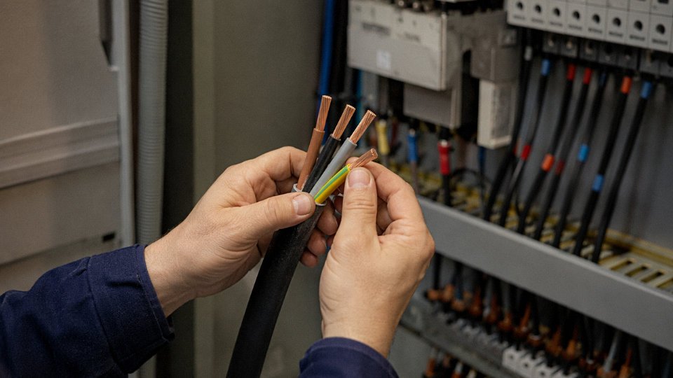
The simplest field check is heat response. Hold a heat gun or even a lighter briefly near the insulation surface — PVC softens and dents under moderate heat, typically above 70–80 °C, while XLPE stays firm because the cross-linked polymer structure won’t flow the same way. XLPE also has a characteristic off-white or milky appearance in cross-section, no waxy feel, and crucially, no plasticizer smell when cut. PVC tends to smell faintly chemical when sliced fresh. For a more structured approach, IEC 60811 describes notch propagation testing, where a small cut is made and the sample bent repeatedly — XLPE resists crack propagation significantly better. In practice most experienced cable hands can tell within seconds just from the cut feel and smell, but don’t rely on that alone for a formal acceptance decision.
What does the number before and after the slash mean in a voltage rating like 0.6/1 kV?
U₀ is the rated voltage from conductor to earth (or metallic screen), and U is the rated voltage conductor-to-conductor. So a 0.6/1 kV cable is designed for systems where the phase-to-neutral voltage doesn’t exceed 600 V and the phase-to-phase voltage doesn’t exceed 1,000 V — which covers standard 400 V three-phase distribution comfortably. Using a 0.6/1 kV cable on a 6/10 kV system is an insulation failure waiting to happen, usually within months rather than years. The third number you sometimes see, such as the “12” in 6/10(12) kV, is the highest system voltage for equipment per IEC 60502, not a separate operational rating.
Can I use a cable rated to one national standard on a project governed by a different standard?
Only after a proper equivalence review — and that review needs to be documented with engineering sign-off, not just an informal agreement. Third-party dual certification (say, both IEC 60502-1 and UL listing) is the cleanest path. Substituting without that review is a code violation in most jurisdictions, and more practically, it hands your insurer a reason to walk away from a claim if something goes wrong.
A cable marked to IEC 60502 can be freely substituted for a UL-listed cable on a UL-governed project without engineering review.False
IEC and UL test protocols, insulation requirements, and conductor sizing conventions differ significantly. Direct substitution without documented equivalence review violates NEC requirements and may void equipment warranties and insurance coverage.
How do I identify the neutral core when insulation colors have faded?
Continuity testing end-to-end is the first step — map each core to its terminal. On a live system, measure voltage between each core and earth: the neutral on a star-connected system will read near zero, while phase conductors read line-to-neutral voltage, roughly 120 V or 230 V depending on the system. Do that work with a qualified electrician using properly rated probes. Always cross-reference your findings against the original cable schedule before marking anything permanently; faded colors have caused more than a few embarrassing re-terminations.
What is the difference between a control cable and an instrumentation cable, and can they be substituted?
Control cables carry switched power — 24 V DC relay logic up to 230 V AC — and are built around insulation rating and current capacity. Individual pair shielding isn’t part of the design. Instrumentation cables are purpose-built around signal integrity: 4–20 mA loops, 0–10 V analog signals, thermocouple pairs. Each pair is individually shielded, usually with an AL/mylar foil plus a drain wire, specifically to kill crosstalk between channels. Run a 4–20 mA signal through an unshielded control cable near a VFD or a contactor bank and you’ll get noise-induced drift that looks exactly like a real process variation. Operators chase ghost faults for days before someone traces it back to the cable choice. Don’t substitute.
How do I find cable ampacity without the datasheet?
Measure the conductor cross-section with a caliper — allow for the stranding geometry when estimating equivalent solid area. Identify insulation type (XLPE versus PVC changes the temperature rating, typically 90 °C versus 70 °C, which directly affects ampacity by roughly 15–25% depending on installation method). Then apply IEC 60364-5-52 tables or NEC Table 310.16 with appropriate derating for grouping, ambient temperature, and installation method. Buried cables in poorly ventilated ducts derate significantly versus free-air single cables, so installation method isn’t optional information. Jinda’s technical support team can pull ampacity tables for any cable in the product range if you supply the conductor size, insulation type, and installation conditions.
Why does some cable have both a foil shield and a braid shield?
They do different jobs. The AL/mylar foil gives 100% circumferential coverage and is effective against high-frequency electromagnetic interference — think switching noise from a VFD above a few kilohertz. The tinned copper braid adds mechanical protection, handles drain current more efficiently at lower frequencies, and gives a reliable, low-resistance termination point for the shield connection. Using foil alone in a VFD cable installation works acceptably at high frequency but the foil tears easily during installation and corrodes at termination points over time. Braid alone leaves gaps in HF coverage. The combination is standard in demanding environments, and worth the small cost premium if you’re pulling cable through a panel full of variable-speed drives.