Specify “4 gauge” on a purchase order without clarifying the standard, and you may receive wire sized to a completely different system — SWG, metric, or IEC — that shares the name but not the conductor area. Run that wire at the load it was never rated for, and you are looking at insulation breakdown, nuisance tripping, or a thermal event inside a conduit nobody can see until the damage is done. The cost of rewiring a panel or replacing a burnt harness runs anywhere from a few hundred to tens of thousands of dollars depending on how deep into the install the mistake gets before someone catches it.
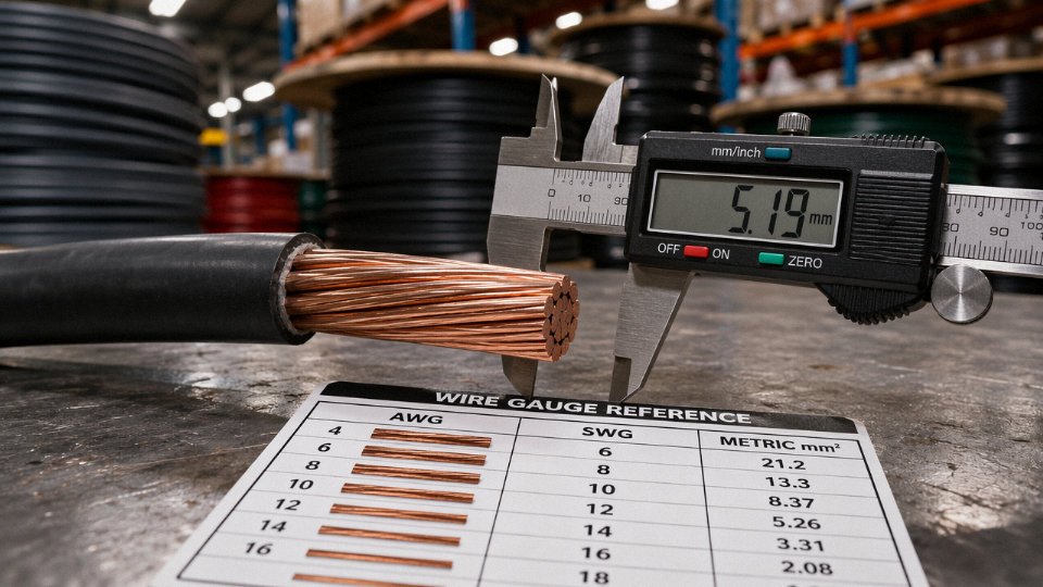
Yes and no. “4 gauge” and “4 AWG” refer to the same wire size when both parties are using the American Wire Gauge system — a conductor diameter of roughly 5.19 mm and a cross-sectional area of about 21.15 mm². The problem is that “gauge” alone is not a system; it is just a number. Unless the AWG standard is explicitly stated, a supplier in a different region may ship to SWG or another gauge table entirely, which produces a different conductor with a different ampacity.
What makes this genuinely tricky is that the AWG system is counterintuitive by design — the larger the gauge number, the smaller the wire, so 4 AWG sits well up the size ladder while 40 AWG is barely a hair. Understanding why that inversion exists, how 4 AWG’s rated ampacity of roughly 85–95 A (dependent on insulation class and installation conditions per NEC Table 310.16) was derived, and where the naming confusion most commonly bites procurement teams is worth a few minutes of anyone’s time before the next cable order goes out.
How the American Wire Gauge System Works: The Math Behind the Numbers
AWG didn’t emerge from thin air. The system was standardized in the United States in 1857, and its logic — counterintuitive as it feels the first time you encounter it — comes directly from the wire-drawing process. To produce thinner wire, a rod is pulled through a series of progressively smaller dies. More drawing passes means a thinner, harder wire. The gauge number itself originally corresponded to the number of die passes required. Pull wire through more dies, you get a higher gauge number and a smaller conductor. That’s why 10 AWG is thinner than 4 AWG, and why 4/0 (0000 AWG) — the fat stuff you see feeding a residential service entrance or a large motor starter — sits at the large end of the scale rather than the small end.
Once you accept that inversion, the rest follows a tightly defined mathematical relationship.
The Formula and What It Actually Tells You
The diameter of an AWG conductor in inches is:
d = 0.005 × 92^((36−n)/39)
where n is the AWG number. Plug in n = 4:
d = 0.005 × 92^(32/39) = 0.005 × 40.865 ≈ 0.2043 inches (5.189 mm)
Cross-sectional area works out to roughly 21.15 mm². That’s not an approximation someone eyeballed — it falls precisely from the formula, and it’s the number you’ll find in NEC Table 310.16 and every reputable wire datasheet for 4 AWG.
A Reference Table Worth Keeping Handy
| AWG Size | Conductor Area (mm²) | Typical Use Context |
|---|---|---|
| 0000 (4/0) | 107.2 | Service entrance, large feeders |
| 2 AWG | 33.6 | Subpanel feeds, EV charging circuits |
| 4 AWG | 21.15 | Motor branch circuits, welding leads |
| 6 AWG | 13.3 | HVAC equipment, smaller motors |
| 10 AWG | 5.26 | General branch circuits, 30 A loads |
The jump from 0000 AWG down to 40 AWG — the thinnest you’ll commonly encounter, at around 0.0799 mm² — spans the entire scale. Most industrial work lives between 10 AWG and 2/0.
The 6-Gauge Rule and the 3-Gauge Shortcut
There’s a practical mental shortcut that experienced engineers use constantly. Every 6-gauge step doubles or halves the cross-sectional area. Go from 4 AWG (21.15 mm²) to 10 AWG, and you’ve roughly quartered the area through two such steps. Every 3-gauge step changes the diameter by a factor of approximately √2 (about 1.414). These aren’t perfectly exact — the logarithmic scale introduces small rounding effects — but they’re close enough for quick field estimates and preliminary cable sizing before you open a conduit fill table.
Solid vs. Stranded: Same AWG, Different Physical Form
A solid 4 AWG conductor is a single wire, 5.189 mm in diameter. Stranded 4 AWG — Class B construction, the most common industrial stranding, typically 7 strands — has the same total cross-sectional area spread across seven smaller wires twisted together. The overall diameter of the stranded version is slightly larger than 5.189 mm once you account for the geometry of bundled circles and the lay of the twist. That matters for conduit fill calculations. It also matters for termination: strand-capable lugs are not always the same as lugs rated for solid conductors, and using the wrong lug type is a real-world source of connection failures and heat damage over time.
Flexibility improves significantly with stranding, which is why welding cables and flexible service cords use finely stranded conductors even at large sizes.
Copper vs. Aluminum at 4 AWG
4 AWG aluminum wire carries the same ampacity as 4 AWG copper wire.False
At the same AWG gauge, aluminum has roughly 61% of the conductivity of copper. A 4 AWG aluminum conductor typically carries around 65–75 A under similar conditions where 4 AWG copper is rated 85–95 A. NEC requires upsizing aluminum conductors — usually by two AWG sizes — to match equivalent copper ampacity, though the exact substitution depends on insulation rating, installation method, and ambient temperature.
Both materials follow the same AWG diameter formula — the geometry is identical — but the electrical performance diverges considerably. Specifying 4 AWG without calling out the conductor material is an incomplete specification. On a procurement document or a drawing, that omission creates real ambiguity, particularly when sourcing internationally where aluminum conductors are sometimes substituted without explicit discussion.
4 AWG vs. 4 mm²: The Metric Confusion That Derails International Cable Orders
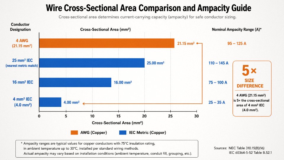
Here is the number that matters: 4 AWG wire has a cross-sectional area of 21.15 mm². A cable labeled “4 mm²” has a cross-sectional area of 4 mm². Those are not close. They are not interchangeable. The difference is roughly a factor of five, and it has caused real overheating events on real installations where a procurement team assumed the gauge number and the metric cross-section were saying the same thing.
They are not.
4 AWG wire and 4 mm² wire are the same sizeFalse
4 AWG has a conductor cross-section of approximately 21.15 mm², while 4 mm² is a metric IEC size closer to 11–12 AWG. Confusing the two produces a cable rated for roughly 32 A where a circuit may demand 85–95 A.
The Numbers Side by Side
This table is worth printing and taping to a purchasing desk.
| Designation | Cross-Section | Approximate Ampacity | Comparable Equivalent |
|---|---|---|---|
| 4 AWG | 21.15 mm² | 85–95 A (60°C, NEC 310.16) | — |
| 16 mm² (IEC) | 16 mm² | 76–87 A (depending on install method) | Closest metric match to 4 AWG |
| 6 AWG | 13.3 mm² | 65–75 A | Between 10 mm² and 16 mm² metric |
| 4 mm² (IEC) | 4 mm² | ~30–32 A | Roughly 11–12 AWG |
Ampacity figures depend heavily on ambient temperature, conduit fill, installation method, and insulation class — always confirm against your local code table, not just this chart.
The closest standard IEC metric size to 4 AWG is actually 25 mm², which sits just above 21.15 mm² and is the nominal metric size most reputable manufacturers map to 4 AWG in cross-reference tables. Some use 16 mm² as the functional ampacity match depending on the application; which one is “right” depends on whether you are matching conductor area precisely or matching current-carrying capacity in a specific installation configuration. That distinction matters when you are writing a cable spec.
Why International Orders Go Wrong
The failure scenario plays out like this: a project manager based in a country that works exclusively in IEC/metric standards needs replacement cable for a 90 A feeder run. The original documentation, written by an American engineer years earlier, calls for “4 gauge wire.” The project manager sends that phrase to a Chinese cable manufacturer without any mm² specification. The factory — entirely reasonably, because in metric-standard production “4” means 4 mm² — ships 4 mm² cable. It arrives, it looks like wire, someone installs it, and the breaker either trips immediately under load or, worse, the cable runs warm for months until insulation degrades.
This is not a hypothetical. It is a predictable consequence of a terminology gap between two parallel, non-interchangeable standards.
AWG is governed by ASTM B258 and referenced throughout NFPA 70 (the NEC). IEC 60228 governs conductor cross-section classes in the metric world. These systems were developed independently and have no built-in conversion factor — there is no formula where you divide or multiply a gauge number to get mm². You look up a cross-reference table, verify the nearest standard size, and specify explicitly.
The Procurement Rule That Prevents This
Always write both values on a purchase order. Not “4 AWG.” Not “21 mm².” Write “4 AWG (21.15 mm² nominal, nearest IEC standard size 25 mm²)” and let the manufacturer confirm which they are supplying. Jinda’s technical team requires both the AWG designation and the nominal mm² cross-section on international cable specifications precisely because this ambiguity shows up on orders regularly — especially from markets transitioning between standards or sourcing mixed-origin equipment.
Quick reference for common sizes: 4/0 AWG ≈ 120 mm², 2/0 AWG ≈ 70 mm², 1/0 AWG ≈ 50 mm², 2 AWG ≈ 35 mm², 4 AWG ≈ 25 mm² nominal. Memorize those five and you will catch most specification errors before they ship.
British Standard Wire Gauge (SWG) vs. AWG: Why ‘4 Gauge’ Still Isn’t Universal
The assumption that “gauge” defaults to AWG is understandable if you’ve spent your career buying wire in North America. Step outside that context — into a UK-origin engineering package, an Indian switchgear datasheet, or a Gulf contractor’s material requisition — and that assumption can cost you a mis-sized conductor running through an already-commissioned panel.
SWG: The Other Gauge System That Never Really Went Away
Standard Wire Gauge, sometimes called Imperial Wire Gauge, is a British standard that predates AWG and still has real traction in markets that inherited British engineering practice. No. 4 SWG wire has a diameter of 0.232 inches (5.893 mm). Compare that to 4 AWG at 0.2043 inches (5.189 mm) and the difference looks modest — roughly 0.7 mm. In cross-sectional area, though, it adds up fast.
| Parameter | 4 AWG | 4 SWG |
|---|---|---|
| Diameter | 5.189 mm (0.2043 in) | 5.893 mm (0.232 in) |
| Cross-sectional area | 21.15 mm² | 27.27 mm² |
| Area difference | — | ~29% larger than 4 AWG |
That 29% gap in cross-section is not a rounding nuance. It changes ampacity, voltage drop calculations, lug sizing, conduit fill, and termination torque specs. If a project engineer designs a circuit around 4 AWG ampacity and receives 4 SWG thinking it’s equivalent, the conductor is actually oversized — which sounds harmless until you realize the termination hardware, compression lugs, and bus bar holes were all sized for the smaller conductor. The wire won’t seat correctly. In the opposite scenario, design to SWG 4 and receive AWG 4: you’ve installed an undersized conductor, possibly without anyone catching it during inspection.
Where SWG Still Shows Up in Practice
SWG remains relevant for bare copper conductors, fuse wire, and certain winding wire applications in UK-legacy markets. India in particular — which has a substantial electrical manufacturing base — still references SWG in older plant documentation, legacy switchgear specs, and some transformer winding drawings. Pakistan and parts of the Gulf Cooperation Council (GCC), especially projects built or extended by British engineering firms in the 1970s and 1980s, may carry SWG references buried in original equipment documentation that gets copy-pasted into new procurement packages without anyone questioning the standard.
In practice, if you’re procuring cable for a refinery expansion in Oman or a substation retrofit in Karachi where the OEM documentation is of British origin, quietly verify which gauge standard the spec is calling out. It’s rarely labeled clearly.
Gauge Is a Word That Means Several Different Things
Beyond AWG and SWG, there are other legacy gauge systems still floating around in specialized industries. Music Wire Gauge applies to high-carbon steel spring wire and uses a completely different diameter sequence. Birmingham Wire Gauge (BWG) is used for steel tubing and hypodermic needles — and its No. 4 diameter differs from both AWG and SWG. Drill gauge systems for metal-cutting tools add yet another set of numbers. The word “gauge” alone carries essentially no dimensional information without its governing standard attached.
A specification document that states '4 gauge wire' without identifying the governing standard is technically ambiguous and could refer to AWG, SWG, or another legacy system.True
AWG and SWG assign different physical diameters to the same gauge number. No. 4 SWG has a diameter of 5.893 mm versus 4 AWG at 5.189 mm — a 29% difference in cross-sectional area — confirming that 'gauge' alone is not a complete specification.
A procurement document from a UK-origin engineering firm that writes “4 gauge wire” without naming the standard could legally and technically mean SWG 4. If your supplier interprets it as AWG 4 — which any North American or Chinese manufacturer almost certainly will — neither party is obviously wrong, and you won’t discover the discrepancy until the wire arrives on site.
How to Remove the Ambiguity Before It Reaches the Factory Floor
The only clean fix is explicit standard citation on every document: purchase orders, RFQs, inspection test plans, and acceptance criteria. For international projects, all cable datasheets issued by Jinda for export supply specify the governing standard directly — either AWG per ASTM B258, or metric conductor class per IEC 60228 — so that gauge-only references never survive into the supply chain. It’s a straightforward policy, and frankly one every procurement team dealing with multi-origin documentation should adopt as a standing requirement rather than something checked case by case.
When you receive an engineering package that uses “gauge” without qualification, push back before issuing the RFQ. One clarification email is cheaper than a container of wrong-sized wire.
Ampacity, Voltage Drop, and Load Calculations for 4 AWG Copper and Aluminum Wire
The electrical data for 4 AWG isn’t complicated, but the number of ways engineers misapply it is. Terminal ratings, ambient temperature, conduit fill, and conductor material all stack on top of each other — get one wrong and you’re either undersized (nuisance trips, overheating) or wildly oversized (wasted copper, wasted money).
NEC Table 310.15(B)(16) Ampacity — What the Numbers Actually Mean in Practice
For 4 AWG copper, NEC Table 310.15(B)(16) gives you 85 A at 60°C insulation, 95 A at 75°C, and 95 A at 90°C. That 90°C column often trips up less experienced specifiers: the conductor itself may be rated for 90°C, but if the lugs or terminals on the equipment are only rated 75°C — which is most standard breaker and panel terminals in North America — you’re legally and practically stuck using the 75°C ampacity of 95 A anyway. The insulation rating tells you what the wire can handle; the terminal rating tells you what the system can handle. Use the lower of the two.
4 AWG copper wire has an NEC ampacity of 95 A when used with 75°C-rated terminalsTrue
Per NEC Table 310.15(B)(16), 4 AWG copper is rated 95 A at the 75°C column, which is the controlling value for most standard equipment terminals in North American installations.
Aluminum changes the picture significantly. 4 AWG aluminum or copper-clad aluminum drops to 65 A at 60°C and 75 A at 75°C — a roughly 20–22% reduction compared to copper at the same gauge. If someone swaps in aluminum to save cost on a run originally designed for copper, they need to either accept the lower ampacity or step up to 2 AWG aluminum to recover it. This substitution error shows up in panel upgrades and feeder runs more often than it should.
Temperature Correction — Especially Relevant in Hot Industrial Environments
The NEC ampacity table assumes a 30°C ambient. Real plants rarely cooperate. At 40°C ambient — a machine room in summer, or a conduit routed near a furnace — you multiply the table value by 0.91. At 50°C ambient, which is common in unconditioned industrial facilities in the Middle East, parts of Southeast Asia, and equatorial Africa, the correction factor drops to 0.82.
Run the math: a 4 AWG copper circuit with 75°C terminations, 95 A table value, at 50°C ambient gives you 95 × 0.82 = roughly 77–78 A usable capacity. That’s before any conduit fill derating. Engineers specifying cables for export projects into hot climates need to build this in at the design stage, not discover it during commissioning.
Conduit Fill and Bundling Derating
Three current-carrying conductors in a conduit is the NEC base case — no derating beyond temperature. Add a fourth through sixth conductor and you apply an 80% factor. Seven through nine conductors, drop to 70% per NEC 310.15(C). Stack a bundling derate on top of a temperature correction and your 95 A conductor might realistically deliver 60–65 A in a dense industrial pull. That’s the kind of thing that causes slow overheating failures rather than immediate trips — which are the worst kind to diagnose.
Voltage Drop Calculation for 4 AWG
The standard formula for a single-phase circuit is:
VD = (2 × K × I × L) / CM
Where K = 12.9 for copper (use 11.2 for aluminum), I is the load current in amps, L is the one-way run length in feet, and CM is the conductor’s circular mil area — 41,740 CM for 4 AWG.
Worked example: an 80 A load on a 50-foot one-way run with copper conductors gives (2 × 12.9 × 80 × 50) / 41,740 ≈ 2.48 V drop. On a 120 V circuit that’s about 2.07% — inside NEC’s 3% guideline for branch circuits. Stretch that same run to 100 feet and voltage drop roughly doubles to 4.1%, which exceeds the recommendation and starts affecting sensitive loads like PLCs, VFDs, or EV chargers. At that point you’re looking at 2 AWG, or re-evaluating the panel location.
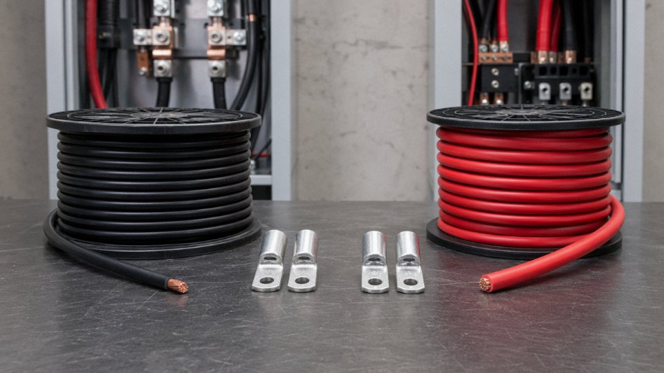
Typical 4 AWG Applications by Load Type
| Application | Conductor | Governing Limit |
|---|---|---|
| Residential 100 A service entrance feeder (short run) | Copper or aluminum | Panel terminal rating |
| Level 2 EVSE up to 80 A continuous | Copper preferred | 80 A continuous = 100 A breaker, check run length |
| Commercial sub-panel feeder | Copper or aluminum | Ampacity + voltage drop combined |
| Marine shore power connection | Copper, tinned | Corrosion and ampacity |
| RV power pedestal feeder | Copper | Pedestal terminal rating |
EV charging circuits deserve a specific note. An 80 A continuous EVSE load is treated as a continuous load under NEC, meaning the overcurrent device must be sized at 125% — so a 100 A breaker on a 4 AWG copper circuit is at the edge. Run length matters here; a 60-foot garage feed is usually fine, but a 120-foot run across a parking structure almost always demands a conductor upgrade or a panel relocation conversation with the owner.
Insulation Types, Jacket Materials, and International Standards for 4 AWG Cable Products
Getting the conductor size right is only half the specification. Pick the wrong insulation system and you’re looking at premature jacket failure, a failed inspection, or — in a wet industrial environment — a safety incident. For 4 AWG conductors specifically, the range of available constructions is broad enough that two cables described identically on a purchase order can perform very differently in the field.
Common NEC/UL Insulation Designations
THHN/THWN-2 is what most North American electricians picture when they hear “4 AWG building wire.” It’s a PVC insulation layer over the conductor with a thin nylon (polyamide) jacket — the nylon is what lets it pull through conduit without shredding. Rated 90°C in dry locations and 75°C in wet, it covers the overwhelming majority of commercial panel feeders and branch circuits. Cost is low, availability is high, and virtually every NEC-compliant installation accepts it. That said, PVC loses flexibility noticeably below about -10°C, which matters if you’re pulling wire in an unheated Canadian warehouse in January.
XHHW-2 steps up to cross-linked polyethylene (XLPE) insulation, which handles 90°C in both dry and wet conditions. The cross-linking process changes the polymer structure so the insulation resists moisture migration far better than standard PVC — relevant for conduits that collect condensation, or anywhere near process equipment with steam or wash-down cycles. It’s also somewhat stiffer on the reel, which some installers find awkward in tight junction boxes.
USE-2 (Underground Service Entrance) is sunlight-resistant and rated for direct earth contact, making it the right call for service laterals and photovoltaic source circuits where the run includes an exposed outdoor segment. RHW-2, rubber-insulated and wet-rated to 90°C, shows up mainly in older industrial specifications and marine applications — it’s genuinely more flexible than XLPE at low temperatures, though it’s harder to source in smaller quantities today.
IEC Constructions for the Metric Equivalent
On IEC projects where 25 mm² is the nearest metric equivalent to 4 AWG (the actual 4 AWG cross-section is ~21.15 mm², so check your derating before substituting), the governing standard is typically IEC 60502-1 for low-voltage power cables up to 1 kV. PVC/PVC construction — PVC insulation over each core, PVC outer sheath — is the standard workhorse. XLPE/PVC replaces the insulation layer with cross-linked PE while keeping the PVC outer jacket; this is the preferred choice for cables that run near heat sources or need a longer service life in humid environments.
EPR (ethylene propylene rubber) insulation appears in flexible cables, offshore installations, and shipboard wiring where sustained flexing or aggressive marine atmospheres rule out thermoplastic options.
Jacket Materials and Environment Matching
The outer jacket choice is often driven by where the cable lives, not what it carries. PVC jackets are fine for standard indoor conduit runs. For tunnels, subway systems, data centers, or any enclosed public space with restricted ventilation, LSZH (Low Smoke Zero Halogen) is the specified material — in a fire, conventional PVC generates hydrogen chloride gas, which is both toxic and corrosive to electronics. The difference in smoke density and toxicity is real, not just a spec checkbox.
CPE (chlorinated polyethylene) jackets earn their place in oil-splash zones, chemical plants, and anywhere petroleum-based fluids are present — PVC will swell and degrade in prolonged hydrocarbon contact, CPE resists it well. HDPE outer sheaths are the standard for direct-burial runs where mechanical protection matters and soil chemistry may be aggressive.
LSZH-jacketed cables produce significantly less toxic smoke than standard PVC-jacketed cables in fire conditionsTrue
LSZH compounds are halogen-free; PVC releases HCl gas and dense black smoke when burned, which is well-documented in fire safety standards including IEC 60332 and BS 7622.
Armoring Options
Steel Wire Armour (SWA) per BS 5467 is the direct-burial standard across UK and Commonwealth projects — the helically applied steel wires provide both mechanical protection and a fault-return path. For single-core cables, aluminum wire armour (AWA) is the correct choice; steel armour on single-core AC cables creates a closed magnetic loop that generates eddy current losses and can cause overheating in service. It’s a mistake that gets made more often than it should.
In North American commercial and industrial work, MC cable per UL 1569 serves a similar role — interlocked aluminum armor over insulated conductors, installable without conduit in most jurisdictions. It’s faster to run than conduit-and-wire systems, though the armor is not a substitute for an equipment grounding conductor in all code interpretations; check your local AHJ.
Color Coding — Specify Both Standards
NEC permits black, red, or blue for ungrounded (phase) conductors in 4 AWG. IEC 60446 specifies brown, black, and grey for the three phases with green-yellow for protective earth. When ordering from an international manufacturer, stating only “4 AWG” without specifying a color standard is an easy way to receive correctly sized wire in the wrong jacket colors — which then requires field re-marking or, in some jurisdictions, a full rework.
Jinda manufactures 4 AWG-equivalent conductors with THHN, XLPE, and LSZH insulation systems, holding certifications to UL 83, UL 44, IEC 60502, and BS 5467. Both AWG-specified North American projects and IEC metric projects can be supported from the same production lines, which simplifies procurement for contractors and distributors managing mixed international project portfolios.
How to Verify 4 AWG Wire Quality: Testing, Certification, and Supplier Qualification
Buying cable on specification and receiving cable on specification are two different things. Anyone who has pulled substandard wire through conduit halfway through a project — only to find the DC resistance blows the voltage drop budget — knows exactly how expensive that gap can be. Here is what to actually check.
Dimensional Verification
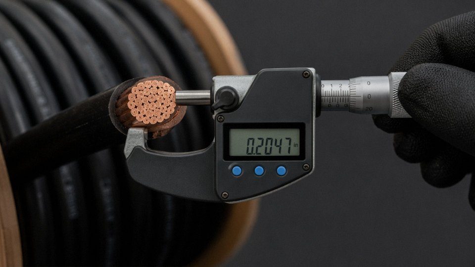
Start with a calibrated micrometer, not a tape measure and not visual inspection. For solid 4 AWG copper, ASTM B3 specifies a conductor diameter of 5.189 mm; stranded 4 AWG per ASTM B8 uses a 7-strand construction where each individual strand should measure roughly 1.96 mm. The overall stranded conductor diameter will be slightly larger than the solid equivalent once the strands are laid up together, typically landing in the 5.7–6.0 mm range depending on lay length and stranding geometry.
One thing to watch: a low-cost supplier will sometimes run the conductor slightly thin — say 4.9 to 5.0 mm — and compensate by thickening the insulation wall so the cable looks correct on a reel and measures out on overall OD. That extra insulation costs far less than the copper it’s hiding. Measure the conductor directly, either on a stripped end sample or by requesting a cross-section from the reel end before accepting the shipment.
DC Resistance Testing
This is the most reliable single test for conductor quality. IEC 60228 Class 2 sets the maximum DC resistance for 4 AWG stranded copper (25 mm² class) at 20°C as 0.727 mΩ/m. ASTM B8 for the North American 4 AWG size puts the limit at ≤ 0.841 Ω per 1,000 ft. If your incoming sample measures 15–20% above those thresholds, the conductor is either undersized, made from recycled copper with elevated impurity content, or both.
Resistance testing requires a four-wire (Kelvin) micro-ohmmeter on a known length — usually a 1-meter or 10-meter sample at ambient temperature, then corrected to 20°C using the standard copper temperature coefficient of 0.00393 per °C. Don’t skip the temperature correction; testing at 35°C on a warm warehouse floor and comparing directly to a 20°C spec will make a borderline conductor look worse than it is, or occasionally better.
IEC 60228 Class 2 specifies a maximum DC resistance of 0.727 mΩ/m for 25 mm² stranded copper conductor at 20°CTrue
This value is published in IEC 60228:2004 Table 2 for Class 2 (stranded) conductors in the 25 mm² nominal cross-section category, which is the metric equivalent class used for 4 AWG in international specifications.
Insulation Resistance
Before energizing any newly installed 4 AWG circuit, test insulation resistance with a 1,000 V DC megohmmeter. Per UL 83 and IEC 60502-1, minimum insulation resistance after water immersion must meet defined megohm-per-foot thresholds — values that depend on insulation material and wall thickness, so pull the exact figure from the applicable product standard. In practice, a healthy THHN or XLPE-insulated 4 AWG conductor tested in a damp conduit run should read well into the hundreds of megohms; anything under 50 MΩ on a short run warrants serious scrutiny before commissioning.
Certifications to Require
For North American projects, the cable must carry a UL Listed mark against UL 83 (for THHN/THWN constructions). EU projects require CE marking with a current Declaration of Performance under the Construction Products Regulation. For projects where the end customer demands independent laboratory validation — power generation, industrial facilities, export infrastructure — require test reports from KEMA, DEKRA, or SGS rather than accepting manufacturer self-certification alone.
Certificate of Conformance and Mill Test Reports
Every reel should come with a Certificate of Conformance carrying a lot number that traces back to a specific production batch, plus a Mill Test Report showing actual measured values: conductor diameter, DC resistance, insulation thickness, and conductor weight per unit length. “Actual measured” means numbers from the production run, not copied specification limits. If the CoC shows exactly the specification minimum and nothing else, that is a red flag — real MTRs have variation.
Jinda provides lot-traceable CoC documentation and third-party SGS or Bureau Veritas test reports as standard on export orders, which simplifies incoming quality control for procurement teams who can’t economically run full test programs in-house on every shipment.
Red Flags on Incoming Inspection
A short list of things that should stop a shipment:
- Conductor diameter below 5.0 mm on a stripped sample from any reel in the lot
- Insulation wall noticeably thicker than spec — suggests the supplier is padding OD to hide a thin conductor
- DC resistance 15% or more above the applicable standard limit
- Copper with reddish-brown discoloration trending toward dark red or black, which can indicate oxygen-free copper that wasn’t, or reclaimed copper with elevated impurities
- Reel footage that does not match label markings when you measure actual run length; short-reeling is common in the low-cost segment and tells you something about the supplier’s quality culture overall
None of these tests require a laboratory. A micrometer, a four-wire milliohmmeter, and a megohmmeter cover the critical checks. The cost of that equipment is trivial against one project delay caused by pulling wire that fails in service.
Sourcing 4 AWG Wire for International Projects: Specification, Logistics, and Supplier Selection
Getting 4 AWG cable onto a project site on time and on spec is straightforward when everything goes right. When it doesn’t — wrong conductor class, ambiguous cross-section, reels that won’t fit the container — the costs compound fast. Here’s how to keep procurement clean from specification through delivery.
Writing a Specification That Leaves No Room for Interpretation
A purchase order that says “4 AWG copper wire, THHN” is not a specification. A real spec for international sourcing should state:
- Conductor material: Electrolytic tough pitch (ETP) copper per ASTM B3 (for drawn wire) or IEC 60228 Class 1/Class 2, depending on whether you need solid or stranded. Don’t assume — Chinese manufacturers default to IEC 60228 Class 2 stranded unless told otherwise, which is correct for most applications but matters if your job spec calls for solid.
- Cross-section, stated twice: 4 AWG and 21.15 mm². This eliminates the substitution risk where a supplier ships 16 mm² or 25 mm² IEC conductor because someone rounded poorly.
- Conductor class: Solid (Class 1) or stranded (Class B per UL, Class 2 per IEC). For conduit pulls over 30–40 ft, stranded is almost always the right call anyway.
- Insulation type and minimum thickness: THHN/THWN-2 per UL 83, or XLPE per IEC 60502-1, with wall thickness explicitly stated in millimeters. Don’t let the supplier interpret “standard.”
- Rated voltage: 600 V (UL) or 0.6/1 kV (IEC) — not interchangeable on paper even if the physical construction overlaps.
- Temperature rating: 90°C dry/75°C wet for THHN/THWN-2, or confirm the IEC equivalent.
- Color code standard: NEC (black, red, blue phase conductors; white neutral; green ground) or IEC (brown/black/grey phase; blue neutral; green-yellow ground). This sounds minor until your electrician shows up on site in Saudi Arabia with a container of NEC-colored cable and a local inspector who expects IEC colors.
- Applicable standards: UL 83, UL 486A-486B, IEC 60502-1, or destination-country equivalents like SASO 2693 for Saudi Arabia or BS 6004 for UK projects.
Minimum Order Quantities and Lead Times
Standard 4 AWG THHN on 500 ft or 1,000 ft spools is a commodity. North American distributors stock it, lead times are days to a couple of weeks, and pricing is competitive. Once you move to custom constructions — armored (SWA or MC), LSZH jacket, dual-rated UL/IEC, non-standard colors — you’re typically looking at 4–8 weeks production lead time and minimum order quantities in the 5,000–10,000 m range from a manufacturer running the job as a production batch. Ordering 2,000 m of armored LSZH 4 AWG from a factory that’s set up for 500 ft THHN rolls is a recipe for delays and inflated unit pricing.
Packaging and Shipping — the Details That Bite You
4 AWG cable for bulk export typically ships on wooden reels for FCL (full container load) shipments, or coiled and boxed for smaller LCL (less than container load) orders. The reel issue trips people up more than it should: large-diameter armored cable reels — anything over roughly 1.2 m flange diameter — may not fit through a standard container door opening (nominally 2.34 m × 2.28 m, but check the actual door clearance on the specific container type). Confirm reel dimensions before the production run, not after.
For LCL coiled orders, agree on maximum coil weight per carton (typically 25–30 kg for practical handling) and confirm inner diameter of the coil won’t cause permanent set in the conductor. Under-radius coiling of 4 AWG stranded copper isn’t catastrophic, but it makes pulling through conduit noticeably harder and can stress the insulation at the bends over time.
Incoterms Selection
FOB Qingdao or FOB Shanghai is the standard term for large project orders sourced from Shandong-based manufacturers — it hands freight and marine insurance control to the buyer, which is usually the right call if you have a freight forwarder you trust. CIF gives you a cleaner all-in number on the invoice but buries freight costs and limits your ability to negotiate rates or choose carriers. For first-time orders with a new supplier, FOB also means you can nominate a surveyor for loading supervision without it feeling adversarial.
Supplier Qualification — What Actually Matters
An ISO 9001:2015 certificate is a baseline, not a qualification. What you actually need:
| Checkpoint | Why It Matters |
|---|---|
| Factory audit report (third-party or self-conducted) | Confirms capacity, equipment calibration, QC process |
| Product test reports from accredited labs (UL, SGS, BV, Intertek) | Verifies conductor resistance, insulation thickness, voltage withstand |
| References from comparable international projects | 4 AWG for a residential developer ≠ 4 AWG for an industrial EPC contractor |
| Confirmed production slot for your delivery window | Avoids the “we can do it” answer that means “we’ll fit you in somewhere” |
| Export documentation capability | SASO, SONCAP (Nigeria), CE Declaration of Conformity, or project-specific third-party inspection |
Jinda operates five production bases across China with over 470,000 m² of manufacturing space, enabling parallel production runs on large international 4 AWG orders without displacing domestic volume.True
This is based on verified company operational data from Shandong Jinda Special Cable Group Co., Ltd. and reflects genuine manufacturing scale relevant to international buyers assessing capacity risk.
A manufacturer with genuine export infrastructure — dedicated documentation staff, familiarity with destination-country certification requirements, in-house testing lab — compresses the back-and-forth that kills project schedules. In practice, getting SASO or SONCAP certification coordinated through a supplier who’s done it before is weeks faster than working with one doing it for the first time. That difference is worth money on a project with a fixed energization date.
Frequently Asked Questions About 4 Gauge Wire and 4 AWG Wire
Is 4 gauge wire the same as 4 AWG wire?
Yes — in North American electrical practice, the two terms mean exactly the same thing. “4 gauge” is just informal shorthand for 4 AWG, where AWG stands for American Wire Gauge. Both specify a conductor with a nominal diameter of 5.189 mm (0.2043 inches) and a cross-sectional area of roughly 21.15 mm². The confusion is understandable because “gauge” appears in several completely different wire standards — AWG, SWG, BWG — and none of them agree on dimensions. So the short answer is yes, but only if everyone in the conversation is working within the North American AWG system. The moment you cross into a UK, Indian, or IEC procurement environment, you need to confirm which gauge standard the supplier is referencing. Put it in writing on the purchase order.
In North American electrical usage, '4 gauge' and '4 AWG' refer to the same standard, specifying a conductor diameter of 5.189 mm and cross-sectional area of 21.15 mm².True
The American Wire Gauge system is the single recognized wire sizing standard in North American electrical codes including the NEC. '4 gauge' is common shorthand and always refers to 4 AWG in this context.
What is 4 AWG equivalent to in metric mm²?
The closest IEC standard size is 25 mm², which is slightly larger than 4 AWG’s 21.15 mm². In practice, most engineers doing international substitution round up to 25 mm², and that’s usually the conservative call — more copper means lower resistance and marginally better voltage drop performance. But “closest equivalent” does not mean “drop-in replacement.” You still need to run voltage drop and ampacity calculations for your specific installation, because conduit fill, ambient temperature, run length, and insulation class all shift the numbers. A 25 mm² cable terminated on a lug sized for 4 AWG can also cause fitment problems at the terminal. Check both the electrical and mechanical compatibility before you sign off.
How many amps can 4 AWG copper wire carry?
Per NEC Table 310.15(B)(16), 4 AWG copper is rated 85 A with 60°C-rated insulation and 95 A with 75°C or 90°C insulation. Those figures assume an ambient of 30°C and no more than three current-carrying conductors in a raceway. Exceed either condition and you derate — ambient correction factors are listed in NEC Table 310.15(B)(2)(a), and bundling correction starts at 80% for 4–6 conductors. In a hot equipment room or a conduit run exposed to summer sun in a southern climate, the usable ampacity can drop noticeably below the table value. Always calculate for worst-case conditions, not average ones.
Can I use 4 AWG aluminum wire instead of 4 AWG copper?
You can, but the numbers don’t line up the way you might hope. Aluminum at 4 AWG is typically rated 65–75 A depending on insulation class, compared to 85–95 A for copper at the same gauge. If you’re targeting a 90 A load, you’d normally upsize to 2 AWG aluminum to stay within code. Beyond ampacity, aluminum requires antioxidant compound at every termination and connectors rated for aluminum — using a copper-only lug on aluminum conductors is a documented failure mode that shows up years later as a high-resistance joint and, eventually, a heat event. Aluminum is a legitimate and cost-effective choice for larger feeders and service entrance runs, but it demands more care in installation than copper.
What is the difference between 4 AWG and 4 SWG?
Quite a lot, actually. British Standard Wire Gauge 4 SWG has a diameter of 5.893 mm and a cross-sectional area of around 27.27 mm² — roughly 29% more conductor material than 4 AWG. They share a gauge number and nothing else. This trips up procurement teams sourcing cable from UK or Indian suppliers when the drawing just says “4 gauge” with no standard called out. The result is usually an oversized cable that doesn’t fit the specified conduit or terminations. Specify the governing standard explicitly on every engineering drawing and purchase order, every time.
Stranded vs. solid 4 AWG — which should I use?
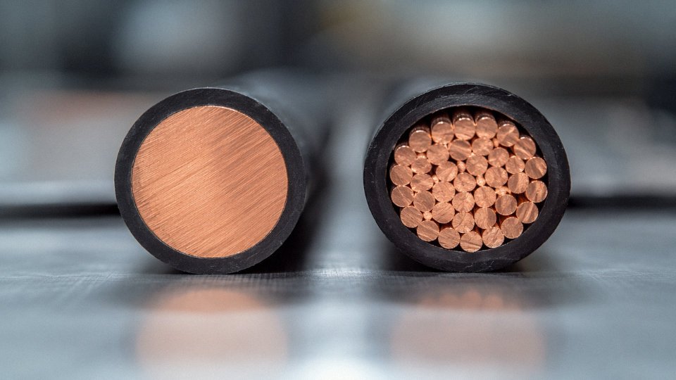
Solid 4 AWG is a single 5.189 mm conductor. It terminates cleanly and resists vibration loosening in fixed installations, which is why it shows up in residential and light commercial in-wall branch circuits. Stranded 4 AWG — typically seven strands in a Class B configuration per ASTM B8 — is meaningfully more flexible and is the standard choice for service entrance cables, panel feeders, motor leads, and any run that requires pulling through conduit or repeated flexing. For most industrial and commercial applications, stranded is the right default. Solid at 4 AWG is borderline stiff to work with in conduit anyway.
How do I order 4 AWG wire from a Chinese manufacturer without getting the wrong size?
Don’t rely on the gauge number alone. Specify in writing: “4 AWG per ASTM B8, nominal cross-section 21.15 mm², Class B 7-strand copper conductor” and then add the insulation type and applicable UL or IEC standard. Providing both the AWG designation and the mm² area is the practical safeguard — a factory working in metric sees 21.15 mm² and knows you don’t mean 16 mm² or 25 mm². Include a request for the conductor resistance value (maximum 0.842 Ω/km per IEC 60228 Class 2 for 25 mm², or the equivalent ASTM B8 value for 4 AWG) as an acceptance criterion on the test report. That single number catches undersized or poor-conductivity conductors before the cable ships.