Specifying the wrong cable for a PoE deployment is one of those mistakes that doesn’t announce itself immediately — it shows up three months later as intermittent switch port faults, overheating patch panels, or a surveillance camera that keeps dropping offline in August when the plant gets hot. By then, the re-pull labor and downtime cost far exceed whatever was saved on cable. Getting the voltage and power rating right before procurement closes the job correctly the first time.
Cat6 cable is rated for a dielectric withstand voltage of 1,000 V AC (rms) during production testing per TIA-568-C.2 and ISO/IEC 11801, though it is designed to operate at the much lower voltages used in structured cabling — primarily the 48–57 V DC range of IEEE 802.3af/at/bt Power over Ethernet systems, with a maximum of 600 mA per conductor pair under PoE++ (802.3bt) at up to 90 W.
What makes this more than a simple lookup exercise is the gap between what the insulation can withstand in a test environment and what the cable should carry on a real network — and, critically, where that gap creates trouble when procurement substitutes a cheaper, thinner-insulated cable that technically claims “Cat6” on the box.
Cat6 Cable Construction and How It Determines Voltage Tolerance
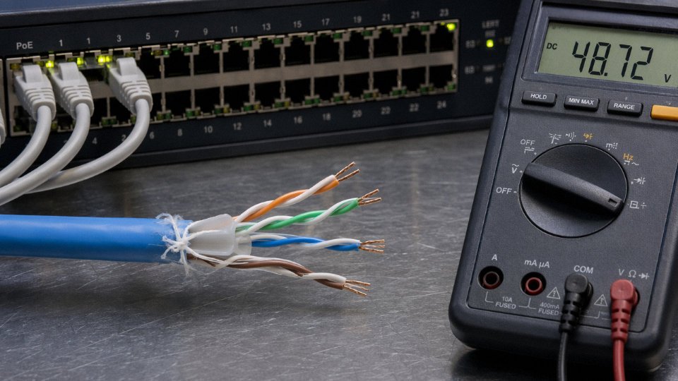
Cat6 performance under voltage isn’t a single material property — it’s the cumulative result of four or five distinct construction decisions, each of which sets a different ceiling. Understanding the stack matters when you’re evaluating a datasheet or writing a procurement specification, because a cable that passes the 1,000 V withstand test can still fail thermally under sustained PoE++ loads if the wrong jacket compound or AWG was selected.
Conductors: AWG, Resistance, and Thermal Load Under PoE
Most Cat6 cables ship with 23 AWG solid copper conductors, though 24 AWG is still common in the market — particularly in lower-cost Asian production runs. The difference matters under high-wattage PoE. A 23 AWG conductor carries roughly 8–9 mΩ/m of loop resistance per pair (depending on purity and drawing quality), while 24 AWG sits closer to 11–12 mΩ/m. Run 600 mA through a 24 AWG pair at full IEEE 802.3bt current over a 90–100 m run, and you’re dissipating meaningfully more heat than the standard assumed when the PoE budget was calculated. In a bundled conduit with 20 or 30 cables, that heat has nowhere to go. Conductor gauge is the first thing to verify, not the last.
Cat6 cables with 24 AWG conductors may require derating for IEEE 802.3bt (PoE++) applications in bundled installationsTrue
Higher resistance in 24 AWG conductors increases I²R heating under 600 mA loads; TIA TSB-184-A derating guidelines apply to bundled cable counts above roughly 24 cables in conduit, and thermal limits may be reached at shorter cable runs than with 23 AWG.
Pair Insulation: Where the 1,000 V Withstand Actually Lives
The individual pair insulation is almost always solid polyethylene, occasionally foam-skin PE in designs optimizing for high-frequency performance. PE is the right material here — it has excellent dielectric strength (typically 20–40 MV/m depending on density and void content), very low dissipation factor, and doesn’t absorb moisture the way PVC does. The wall thickness on a Cat6 conductor insulation layer is typically 0.15–0.20 mm, which is thin but sufficient for the 1,000 V AC, 60-second production withstand test required by TIA-568-C.2 and ISO/IEC 11801. That test is a manufacturing quality gate, not an operating spec — the cable is never expected to see 1,000 V in service.
What the insulation wall thickness really controls, in practice, is the margin against pinhole defects, eccentricity, and long-term dielectric degradation. A cable with consistently concentric insulation (measured by the eccentricity ratio on the production line) will hold its withstand voltage over a 15–20 year service life. A cheap cable with variable wall thickness might pass the factory test and still develop intermittent insulation breakdown at the bends after a few years of thermal cycling.
The Spline Separator and Jacket: Fault Containment, Not Just Geometry
Many Cat6 designs include a central cross-shaped spline — usually extruded HDPE — that physically separates the four pairs. Its primary job is maintaining pair geometry for crosstalk performance, but it has a secondary voltage-related benefit: it adds a physical barrier that slows arc propagation between pairs in a fault scenario. This isn’t a formal rated function in most specs, and you won’t see it listed in a voltage table. Still, in a fault condition — a conductor nicked during installation, a compression connector crimped too hard — that separator is the difference between one failed pair and a cable that propagates a fault across all four.
The outer jacket — PVC, LSZH, or plenum-rated FEP or low-smoke compounds — doesn’t influence normal operating voltage in any meaningful way. Its role is environmental protection and, critically, flame and arc propagation resistance in fault or fire scenarios. PVC jackets can track (form conductive carbonized paths) under sustained arc, which is why plenum-rated compounds use halogen-free or fluoropolymer materials with much higher comparative tracking index (CTI) values.
How Cat6 Compares to Cat5e and Cat6A
Cat5e typically uses 24 AWG conductors with thinner overall insulation walls and no spline separator. That combination is why Cat5e is generally considered marginal for IEEE 802.3bt installations — the thermal headroom under four-pair, 90 W PoE loads is tight, especially in any bundled or conduit run longer than 60–70 m. It’s not that Cat5e will fail immediately; it’s that you’re operating with little margin, and margin is what keeps you from scheduling emergency recabling in year three.
Cat6A steps up to 23 AWG (sometimes 22 AWG in shielded variants), thicker individual insulation walls, and a more robust jacket cross-section — all of which reduce I²R heating, improve thermal dissipation, and maintain safe operating temperature at full IEEE 802.3bt current without derating. The tradeoff is cable diameter (typically 7–8 mm vs. 5–6 mm for Cat6), which affects conduit fill calculations and bend radius management. For a new PoE++ deployment, Cat6A is the right choice. For an existing Cat6 infrastructure, the answer depends on conductor gauge, bundle count, and run length — all things a procurement spec should lock down explicitly.
TIA-568, ISO/IEC 11801, and IEC 60332: The Standards That Define Cat6 Voltage Limits
The single most common mistake I see in procurement specs is treating the 1,000 V AC dielectric withstand figure as if it were the cable’s continuous operating limit. It is not. Understanding what each standard actually tests — and what it deliberately leaves unspecified — is what separates a competent cable specification from one that creates liability downstream.
TIA-568-C.2: What It Tests and What It Intentionally Omits
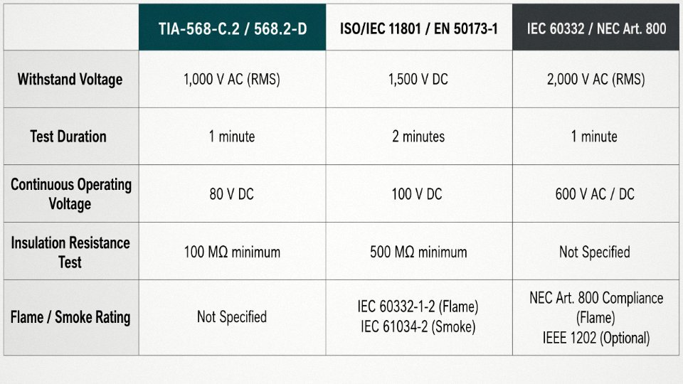
TIA-568-C.2 (and its successor revision, TIA-568.2-D) requires that each completed Cat6 cable pass a dielectric withstand test at 1,000 V AC rms, held for 60 seconds, applied between all conductors bundled together and, for shielded variants (F/UTP, S/FTP), between the conductor bundle and the overall shield. The cable must show no breakdown, no flashover, no sustained arc. That’s the pass/fail criteria. The test is a production screening tool, not a continuous-duty rating — it verifies that no pinhole, nick, or thin spot in the HDPE or FEP insulation will cause an immediate dielectric failure.
What TIA-568-C.2 does not specify is a continuous AC or DC operating voltage limit. None. The standard concerns itself with transmission performance — insertion loss, NEXT, return loss, propagation delay, mutual capacitance in the range of roughly 45–75 nF/km depending on geometry and dielectric — not with sustained electrical stress on the insulation wall. When you’re writing a procurement specification and you want to guarantee PoE+ or PoE++ compatibility, you cannot simply cite TIA-568-C.2 and call it done. You need to call out the IEEE 802.3at or 802.3bt compliance requirement separately, and verify the conductor gauge (AWG 23 or AWG 24 solid, which affects resistance and thus voltage drop at load) and the jacket heat rating.
TIA-568-C.2 specifies a continuous operating voltage limit for Cat6 cable.False
TIA-568-C.2 only specifies a 1,000 V AC dielectric withstand test for 60 seconds as a production quality screen. It does not define a continuous operating voltage. Engineers must reference IEEE 802.3 PoE standards separately for operating voltage requirements.
ISO/IEC 11801, EN 50173, and IEC 60512-2 Factory Testing
ISO/IEC 11801 (the international structured cabling framework) and the European harmonized version EN 50173-1 align closely with TIA on withstand voltage — the test voltage and duration requirements are essentially equivalent, which simplifies international project specifications. Where they diverge is in channel length assumptions and some link model definitions, not in the electrical safety parameters.
The factory insulation resistance test, governed by IEC 60512-2-1, is where you get a more operationally meaningful number. A conforming Cat6 cable should show insulation resistance typically above 500 MΩ per 100 m at 500 V DC test voltage. Cables that pass the 1,000 V AC withstand but show marginal insulation resistance — say, 80–120 MΩ — usually have a contamination or compound mixing issue, and in a high-humidity installation environment (outdoor conduit, coastal plant floors, food processing areas with washdown cycles) you will see that number degrade further in service. Always request the IEC 60512-2 test data by batch, not just by cable type, when sourcing from a new supplier.
IEC 60332, NEC Article 800, and the Fire/Voltage Intersection
IEC 60332-1 tests single-cable flame spread; IEC 60332-3 covers bunched cables in a vertical tray, which is the more demanding scenario and the one that actually matters in a data center or factory cable run. Jacket compound selection — low-smoke zero-halogen (LSZH) polyolefin versus standard PVC — is driven primarily by these flame tests, not by voltage rating directly. The voltage performance of LSZH versus PVC jackets at 48–57 V DC is essentially identical in practice.
North American NEC Article 800 CMP (plenum) and CMR (riser) ratings introduce a combustion performance requirement tied to UL 910 and UL 1666 test protocols respectively. CMP-rated cables use FEP or low-smoke PVC compounds that also happen to have excellent dielectric properties — the dielectric constant of FEP is roughly 2.1 versus 3.5–4.0 for standard PVC — which marginally improves high-frequency signal integrity, though at meaningful cost premium. For global procurement teams reconciling NEC requirements against IEC 60332-3, the practical guidance is straightforward: a cable certified to IEC 60332-3 Category C or B will usually satisfy riser (CMR) performance intent, but CMP plenum rating has no direct IEC equivalent and requires separate UL listing for North American installations. Do not assume one substitutes for the other on a permit-required job.
Power over Ethernet Voltages on Cat6: IEEE 802.3af, 802.3at, and 802.3bt Compared
PoE is where Cat6 voltage ratings stop being a purely academic concern and start affecting real hardware decisions. The insulation withstand figures from TIA-568 and ISO/IEC 11801 give you a ceiling, but PoE is what actually puts sustained DC voltage and current through the copper — and with 802.3bt now common in access-layer switches, that current is high enough to generate meaningful heat inside bundled cable runs.
What Each PoE Generation Actually Puts on the Wire
The three IEEE standards represent roughly a decade of escalating power budgets, and each one changes the thermal and electrical load on your Cat6 conductors in a different way.
| Standard | Max PSE Output | Voltage Range (PSE) | PD End Voltage (min) | Max Current per Pair | Pairs Used |
|---|---|---|---|---|---|
| IEEE 802.3af (PoE) | 15.4 W | 44–57 V DC | 37 V | ~350 mA | 2 pairs |
| IEEE 802.3at (PoE+) | 30 W | 50–57 V DC | 42.5 V | ~600 mA | 2 pairs |
| IEEE 802.3bt Type 3 (PoE++) | 60 W | 50–57 V DC | 42.5 V | ~600 mA per pair | 4 pairs |
| IEEE 802.3bt Type 4 (PoE++) | 90 W | 52–57 V DC | 41.1 V | ~960 mA per pair | 4 pairs |
The voltage range shown is at the power sourcing equipment (PSE) — the switch or injector. By the time you reach the powered device (PD), resistive losses along 100 m of 24 AWG conductor have already dropped several volts. That’s not a safety issue for the insulation, but it matters for devices with tight input voltage windows. A PTZ camera or thin-client terminal sitting at the far end of a marginal run can brown out even when the switch port is technically compliant.
Thermal Load: Where 802.3bt Gets Serious
For 802.3af and even 802.3at, conductor heating on Cat6 is modest — generally 3–6°C above ambient in free-air runs, give or take depending on ambient temperature and whether the cable is coiled in a ceiling plenum or lying flat. Most installers never think about it, and usually they’re right not to.
802.3bt Type 4 is different. At 90 W across all four pairs on a 100 m Cat6 24 AWG run, resistive heating can push conductor temperatures 10–15°C above ambient. That doesn’t approach the insulation limit, but it degrades insertion loss performance — because copper resistance increases with temperature, roughly 0.4% per degree Celsius — and it compounds when cables are bundled. TIA TSB-184-A addresses this directly: it introduces derating tables based on bundle size and conduit fill. A cable in a 12-cable bundle inside conduit may need to be derated to 50–60 W maximum per cable, depending on ambient. Ignore this and you’re not violating insulation voltage ratings, but you are degrading signal performance on the same conductors carrying the power. That’s how you end up with intermittent link drops that take weeks to diagnose.
TIA TSB-184-A provides specific derating guidance for PoE power limits based on cable bundle size and conduit fillTrue
TSB-184-A (A Guide for Powering over Balanced Twisted-Pair Cabling) was published by TIA specifically to address thermal management concerns in PoE installations, including bundle derating factors for various fill scenarios.
Cat6 vs. Cat6A for High-Power PoE: A Practical Verdict
The honest answer is that standard Cat6 at 24 AWG is technically within spec for 802.3bt, but it’s working closer to its thermal limits than most engineers are comfortable with — especially in warm machine rooms, dense bundles, or tropical climates where ambient is already 30–35°C before the cable adds anything.
Cat6A typically uses 23 AWG conductors. That sounds like a small step, but the cross-sectional area difference is roughly 26%, which reduces DC loop resistance meaningfully and cuts I²R heating proportionally. BICSI TDMM and TIA-568-C.2 both lean toward Cat6A for 802.3bt Type 3 and Type 4 deployments for exactly this reason. The larger overall diameter of Cat6A also makes derating in bundles somewhat more conservative, but the thermal performance of the conductor itself is better.
In practice, if you’re deploying 802.3bt to power access points, digital signage, or small switches in a new build, spec Cat6A from the start. Retrofitting Cat6 that’s already in conduit is painful, and the cost delta between Cat6 and Cat6A at project scale is usually 15–25% on cable material — far less than a single service call to troubleshoot thermal-induced packet loss six months after handover.
Voltage Drop, Impedance, and Signal Integrity Over 100-Meter Cat6 Runs
The 100-meter channel limit for Cat6 isn’t arbitrary — it’s the point where DC resistance, attenuation, and crosstalk all converge at their worst acceptable values simultaneously. Push beyond it, or run cable through a hot ceiling plenum while loading it with PoE++, and you may be technically within the channel length limit yet still watching devices brown-out or links drop to 100 Mbps.
DC Loop Resistance and PoE Voltage Drop
Start with the math nobody prints on the box. Solid 24 AWG copper carries a nominal resistance of roughly 9.38 Ω per 100 m per conductor — though in practice, conductor diameter tolerances and the purity of the copper alloy used can shift that figure by 3–5%, so always check the manufacturer’s datasheet rather than assuming the nominal. A 100 m run uses two conductors in series (the loop), giving you approximately 18.8 Ω of total loop resistance.
Now apply that to IEEE 802.3bt PoE++: worst-case PSE output can be as low as 50 V at the switch port, and the cable must carry up to 600 mA per conductor pair. Ohm’s law gives 18.8 Ω × 0.6 A = 11.3 V dropped in the cable. That leaves roughly 38.7 V arriving at the powered device — which is uncomfortably close to the minimum 37 V that many PD (powered device) controllers require to stay in regulation. At exactly 100 m, with a PSE that’s outputting at its lower spec limit, you can fail to power the device without any fault in the cable at all.
This is exactly the kind of situation that generates “intermittent PoE failures” tickets. The device powers up, draws startup current which causes a momentary deeper sag, the PD controller sees undervoltage, and the cycle repeats. Stranded conductor cable makes this worse — stranded 24 AWG typically runs 10–11% higher resistance than solid, which can add another 1.5–2 V of drop on a full run.
A 100 m Cat6 run with solid 24 AWG copper drops approximately 11 V at 600 mA PoE++ loading, which can push the PD below its minimum operating voltage if the PSE outputs near its lower compliance limit.True
DC loop resistance for 24 AWG solid copper is approximately 18.8 Ω over a 100 m two-conductor loop. At 600 mA, V = IR = 18.8 × 0.6 = 11.28 V. IEEE 802.3bt specifies a minimum PD input voltage of 37 V, and PSE output minimum is roughly 50 V, leaving ~38.7 V at the PD — a margin of less than 2 V.
Characteristic Impedance Is Not a Voltage Rating
Cat6 is specified at 100 Ω ± 15 Ω characteristic impedance, and this confuses a surprising number of procurement buyers who ask whether the “100 ohm rating” means it can only handle 100 V. It cannot — characteristic impedance is a frequency-domain property that describes how the cable looks to a traveling wave. It’s determined by the ratio of conductor diameter to insulation outer diameter and the dielectric constant of the insulation material. It has essentially nothing to do with how much DC or low-frequency AC voltage the cable can withstand.
Mismatches in characteristic impedance — connecting Cat6 to a patch panel designed for Cat5e, or using the wrong keystone jack that changes the geometry at the termination — cause signal reflections that raise return loss and reduce usable bandwidth. The 15 Ω tolerance exists precisely because real-world installations involve bends, punch-downs, and connectors that perturb the ideal geometry. Buying cable that measures 95 Ω or 112 Ω off the drum isn’t necessarily a problem if it’s within spec, but a vendor who can’t provide swept impedance test data on request is a vendor I’d be skeptical of.
Attenuation, Temperature, and Why They’re Linked
TIA-568-C.2 sets the maximum insertion loss for a 100 m Cat6 channel at 21.3 dB at 250 MHz, measured at 20°C. That temperature qualifier matters more than most installers realize.
PoE current heats the conductors. At 600 mA through 24 AWG, the resistive heating is modest in open air, but cable bundled in conduit or run inside a tight cable tray accumulates heat. Attenuation increases at approximately 0.4% per degree Celsius above the 20°C reference. A bundle of 20 Cat6 cables in a conduit in a roof space that reaches 45°C in summer represents a 25°C rise — adding roughly 10% to the attenuation of every cable in that bundle, pushing some marginal runs over the 21.3 dB limit. The result isn’t always a complete link failure; often it’s a link that negotiates at 1 Gbps in December and spontaneously drops to 100 Mbps in July, which is genuinely difficult to diagnose without a field tester that logs attenuation versus time.
The thermal and voltage-drop effects compound each other. Higher resistance due to temperature means more voltage drop for PoE devices. More current from PoE devices means more resistive heating. In dense IP camera or access-point deployments where nearly every port runs PoE+, the thermal design of the cable pathway is as important as the cable specification itself. Derating cable fill in conduit, using Cat6A (which runs larger conductors and handles heat better) for runs above 70 m with PoE++, and verifying PSE output voltage at the switch under full load — these are the practical steps that prevent a correctly specified installation from failing in service.
Shielded vs. Unshielded Cat6: Voltage Isolation, Ground Loops, and EMI in Industrial Environments
Walk through any active manufacturing floor — a facility with variable frequency drives cycling on 50 Hz motors, fluorescent or LED high-bay fixtures with switching ballasts, and bus ducts running 400 V three-phase within a meter of your network tray — and the question of whether to use UTP Cat6 becomes a lot less academic. The shield construction you specify determines how much of that ambient electrical noise couples into your signal pairs, and it affects fault voltage isolation in ways that matter when something goes wrong upstream.
The Four Constructions and What Each One Actually Does
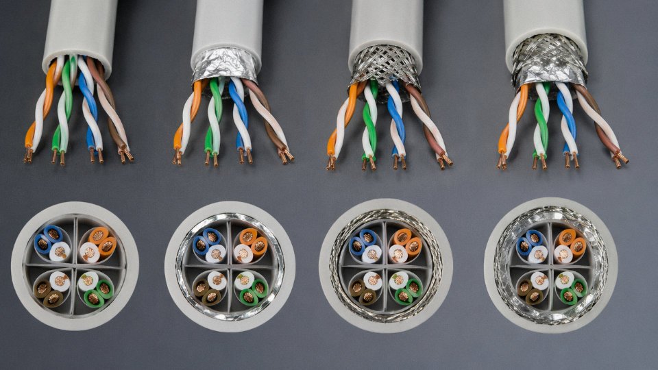
UTP (unshielded twisted pair) relies entirely on the twist geometry of each pair to cancel common-mode noise. That works well in office environments. In a plant with VFDs, it frequently doesn’t — induced voltages from steep PWM switching edges can reach several hundred millivolts on unshielded pairs even at modest cable-to-power separations, well above the noise margin your switch or IP camera can tolerate reliably.
F/UTP adds a single aluminum-polyester foil wrap around all four pairs. This is the most common “shielded” Cat6 you’ll see quoted by distributors, and it handles moderate EMI environments reasonably well. The foil is bonded to a drain wire running the length of the cable, which is your grounding point. Coverage is effectively 100% for the foil layer itself, though the drain wire becomes the weakest link if it’s nicked during termination.
S/UTP substitutes a braided copper screen for the foil. Braid is more mechanically robust — it survives repeated flexing in cable-track applications — but typical braid coverage runs 85–92%, leaving some gaps at high frequency. The tradeoff is real: braid handles sub-100 MHz noise better than foil in many cases because of lower transfer impedance, but foil wins at the high-frequency end where VFD switching harmonics live.
SF/UTP (sometimes labeled S/FTP on datasheets, which describes individually foil-shielded pairs plus an overall braid) is the configuration you want for genuinely harsh environments. The per-pair foil screens each signal pair independently, reducing crosstalk-induced voltage between pairs under high-current PoE, while the outer braid absorbs the bulk EMI from external sources. This is not cheap, and it’s heavier and stiffer than F/UTP, which matters when you’re pulling through conduit with tight bends. But in a cabinet directly adjacent to a 75 kW VFD, it’s usually the right call.
Ground Loops: The Failure Mode Nobody Talks About Until Equipment Burns
Here’s the trap that catches even experienced installers: you spec shielded Cat6, you terminate it with shielded keystone jacks and shielded patch panels, and then somebody bonds the shield at both ends — the switch cabinet at one end, the IP camera enclosure at the other — without verifying those two ground references are at the same potential. In a large plant, the potential difference between a substation ground and a remote panel ground can easily run 2–8 V at 50 or 60 Hz under normal load, and worse during a fault event.
That voltage rides the shield, couples capacitively into the signal pairs, and either causes persistent bit errors or, in edge cases, stresses the PHY inputs on your equipment. IEC 60603-7 and TIA-568-C.2 Annex H are explicit: the shield drain wire should be bonded at one end only in installations where ground potential differences cannot be controlled, or both ends should connect to a common equipotential bonding network that meets IEC 60364-5-54 requirements. Single-end bonding at the distribution frame is the common field compromise. It’s not perfect — it leaves the far end floating and sacrifices some low-frequency shielding effectiveness — but it eliminates the ground loop. In practice, most industrial network installers default to single-end grounding and accept the tradeoff.
Shielding a Cat6 cable at both ends always improves noise immunityFalse
Double-end grounding of a shielded Cat6 cable only improves noise immunity if both ground reference points are bonded to a true equipotential network. In typical plant installations with separate ground paths, double-end bonding creates a ground loop that introduces 50/60 Hz noise voltages onto the signal reference, often making performance worse than a properly single-end grounded or even unshielded installation.
Jinda’s Production Controls for Shielded Cat6
On the manufacturing side, the voltage safety of a shielded cable depends on controls that happen before the cable leaves the factory. At Jinda’s production facilities, every meter of insulated conductor passes through a spark tester — applied voltage typically in the 2–6 kV AC range depending on insulation wall thickness and the applicable standard — which catches pinholes or thin spots in the dielectric before the conductor is twisted into pairs. A pinhole that passes spark testing at 1 kV might survive lab conditions and fail under sustained PoE current in a warm cable bundle. The spark test voltage is intentionally set above the IEC 60189 production test threshold to catch marginal insulation.
Shield coverage on Jinda’s F/UTP and S/FTP Cat6 products is measured per production lot, with a minimum specified coverage of 85% for braid layers and verified 100% coverage for foil-plus-drain constructions. Before shipment, every reel undergoes 100% continuity testing of the drain wire and shield, plus insulation resistance testing per IEC 61156 to confirm the dielectric hasn’t been compromised during stranding or jacketing. These aren’t just datasheet claims — they’re part of the outgoing QC record that ships with the reel documentation, which matters when you’re qualifying a supplier for a long-term procurement program and need traceability.
For procurement teams specifying Cat6 for industrial or outdoor enclosure applications: ask your supplier for the spark-test voltage used in production, the measured shield coverage figure (not the nominal), and whether the insulation resistance test is 100% or sampled. The answers tell you a lot about how seriously the manufacturer takes the voltage side of what most people treat as a pure data cable.
Common Installation Mistakes That Compromise Cat6 Voltage Safety and Performance
Most Cat6 voltage failures in the field don’t trace back to bad cable. They trace back to installation decisions that looked harmless at the time — conduit fill that seemed fine, a patch cord grabbed from the spares bin, cable ties pulled just a little too tight. The damage shows up weeks or months later as intermittent PoE dropouts, overheated jacket sections, or bit-error rates that creep up in summer and disappear in winter. Here are the five mistakes that cause the most damage, and what to do differently.
Bundling High-Density PoE Cable in Overfilled Conduit
Heat is the silent killer in dense PoE deployments. Each conductor carrying 600 mA under IEEE 802.3bt is dissipating real power as resistive loss — roughly 1–2 W per 100 m pair depending on conductor gauge and ambient temperature — and when you bundle 30 or 40 of those cables into a conduit that’s already at 40% fill, the mutual heating effect can push jacket temperatures well above the 60°C threshold that standard Cat6 PVC insulation is rated for. TIA-568.2-D acknowledges this and requires derating: in bundles of 24 or more cables carrying continuous PoE loads, you should derate to 50% or less of the individual cable’s rated ampacity. In practice, that often means upsizing conduit by one trade size, splitting runs, or switching to a low-smoke halogen-free jacket compound with a higher thermal rating. Seasonal effects matter here too — a conduit routed through a roof space that hits 55°C in August is already starting from a bad position.
Using Cat5e Patch Cords on Cat6 Horizontal Runs
This one happens constantly in retrofit projects. Someone terminates a full Cat6 channel and then connects it with a Cat5e patch cord from the patch panel to the switch. Cat5e conductors are typically 24 AWG with higher DC resistance per unit length than a well-made Cat6 patch cord, and at 100 m with PoE++ current flowing, that extra resistance in the patch cord adds meaningful voltage drop at the powered device end. The channel resistance budget for 802.3bt compliance is tight; adding even 0.5–1 Ω of unexpected resistance can push the PD supply voltage below the 37 V minimum the standard requires. Always match patch cord category to the horizontal cable.
Exceeding 100 m Without Mid-Span Injectors
The 100 m channel limit for structured cabling isn’t arbitrary — at 90 m of horizontal cable plus a 10 m combined patch allowance, the conductor resistance is at the edge of the PoE++ power budget. Push to 120 m and the PD may receive less than 37 V, which either causes the device to reset or forces it to operate in a degraded power class. The fix is a mid-span injector or a powered switch closer to the load, not thicker cable.
Stapling Cable and Over-Cinching Tie Wraps
A staple gun used on data cable is always wrong. Even a tie wrap pulled too aggressively — enough to slightly deform the cable’s round cross-section — compresses the twisted pairs unevenly, disrupts their twist geometry, and introduces impedance discontinuities that show up as elevated return loss in TDR testing. The IEEE 802.3bt receiver can compensate for some of this, but you’re burning margin you’ll need later. Use hook-and-loop straps, not zip ties cranked tight, and keep bend radius above 4× the cable’s outer diameter minimum.
Running Cat6 Alongside 240 V AC Conductors
NEC Article 800 and TIA-569-D require a minimum 50 mm separation between Cat6 and power conductors below 480 V, and 100 mm above 480 V, unless a metallic conduit barrier is used.True
This is correctly stated per NEC Article 800.133 and TIA-569-D Section 9, which specify minimum separation distances for communications cables routed near power conductors to prevent inductive coupling and insulation stress.
Shared conduit with line-voltage conductors is a code violation in most jurisdictions, but the more insidious problem is inductive coupling from unbalanced 240 V loads degrading signal-to-noise ratio across the Cat6 pairs. In industrial plants — near VFD panels, welding drops, or lighting ballast circuits — even physically adjacent but separate conduits can cause problems if there’s no metallic barrier. The 50 mm / 100 mm separation rules give you a minimum; in high-EMI environments with high-current motor feeders nearby, 200–300 mm is a more defensible design choice.
Where Engineering Support Matters More Than the Cable Spec Sheet
Routing plans, conduit fill calculations, and PoE derating tables are things a cable spec sheet won’t do for you. For international project buyers managing large-scale structured cabling deployments — data centers, industrial facilities, smart buildings across multiple buildings or campuses — Jinda’s technical support team works directly with OEM and bulk-purchase clients on exactly this kind of pre-installation engineering. That includes reviewing single-line routing diagrams, running derating calculations for specific bundle sizes and ambient conditions, and flagging separation violations before conduit is poured or trays are installed. In my experience, that level of pre-project coordination is where procurement errors get caught — not during commissioning, when fixing them costs five times as much.
Cat6 Voltage Ratings in Specific Applications: Data Centers, Industrial Ethernet, and Outdoor Runs
Generic Cat6 articles stop at “48 V PoE, 1,000 V dielectric withstand, done.” That’s fine for a simple office drop. It’s inadequate once you’re specifying cable for a hyperscale data hall, a PROFINET ring on a stamping press floor, or a direct-burial run between buildings in a coastal climate. Each of those environments introduces stresses — thermal, mechanical, chemical, moisture — that interact directly with how the cable handles voltage.
Data Centers: Thermal Derating Is Not Optional
Hot-aisle/cold-aisle containment works well for servers. It’s harder on cable bundles running along the hot-aisle ceiling, where ambient temperatures in some deployments reach 35–45°C without anyone flagging it as unusual. At those temperatures, the insulation isn’t failing — but the conductor’s current-carrying capacity is reduced, and with IEEE 802.3bt Type 4 pushing up to 600 mA per pair, that matters.
TIA TSB-184-A defines bundle derating for PoE. The logic: more conductors packed together, less heat dissipation per conductor, so you either reduce the number of active PoE pairs per bundle or you accept temperature rise that degrades insulation life and, eventually, signal margin.
Sample derating — IEEE 802.3bt Type 4, Cat6, based on TIA TSB-184-A guidance:
| Bundle Size | Max Active PoE Pairs @ 25°C | Max Active PoE Pairs @ 35°C | Max Active PoE Pairs @ 45°C |
|---|---|---|---|
| 1 cable | 4 | 4 | 4 |
| 4 cables | 4 | 3–4 | 3 |
| 12 cables | 3–4 | 3 | 2–3 |
| 24 cables | 2–3 | 2 | 1–2 |
Exact figures depend on jacket material, conduit versus tray installation, and airflow. These are indicative ranges, not a substitute for your project’s thermal calculation. The takeaway: a 24-cable bundle in a 45°C hot aisle running full 802.3bt may need to limit active pairs to roughly half of what you’d allow at room temperature. Specify Cat6 with a LSZH or plenum-rated jacket where your data center standard requires it, and confirm the jacket’s rated temperature ceiling before assuming standard PVC is acceptable.
Industrial Ethernet: Same Dielectric Floor, Very Different Jacket
PROFINET and EtherNet/IP installations in manufacturing environments need Cat6 cable built to IEC 61156-5, which addresses industrial structured cabling and includes requirements for flexing life, oil resistance, and the wider operating temperature range — typically -40°C to +75°C versus the -20°C to +60°C you’d expect from a commercial Cat6 product.
The insulation dielectric withstand floor stays the same: 1,000 V AC for 60 seconds per conductor-to-conductor and conductor-to-shield test. What changes is the jacket. Polyurethane and TPE compounds resist the hydraulic fluid, coolant mist, and cleaning solvents that destroy standard PVC jackets in months. On a press line or a robotic welding cell, the cable also flexes continuously, so the insulation compound needs to maintain its dielectric properties through millions of flex cycles, not just in a static pull test.
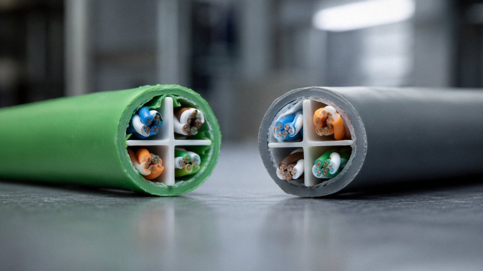
In practice, don’t assume a commercial Cat6 reel from a network closet project is suitable just because it physically fits in an M12 connector. The voltage rating may be identical on paper; the service life under oil and flex loading will not be.
Outdoor and Direct-Burial: Moisture Is the Hidden Voltage Risk
UV exposure degrades PVC jackets over roughly 3–5 years depending on climate and UV index — faster in equatorial or high-altitude sites. Direct-burial Cat6 needs a UV-stabilized polyethylene jacket as a baseline, and for runs in waterlogged or clay-heavy soil, a PE-filled or gel-filled construction that blocks moisture wicking along the core. Moisture ingress doesn’t immediately cause insulation failure, but water treeing in degraded PE insulation over years can reduce the dielectric withstand voltage well below the 1,000 V production test floor.
Direct-burial Cat6 carries the same 1,000 V AC insulation withstand voltage as indoor grades when properly specifiedTrue
IEC 60794-1 outdoor cable testing protocols include dielectric withstand requirements consistent with TIA-568 and ISO/IEC 11801 indoor standards — the outdoor jacket and flooding compound address moisture and UV, not a different voltage class.
IEC 60794-1 covers outdoor cable test methods, including water penetration, UV aging, and crush resistance. Confirming your direct-burial Cat6 is tested to those protocols — not just described as “outdoor rated” on the box — is worth a datasheet review before the cable goes in the ground. Armored Cat6, with a corrugated steel or aluminum tape over the PE jacket, adds crush and rodent protection for direct-burial in high-traffic or agricultural sites. Jinda supplies both PE-jacketed outdoor Cat6 and armored Cat6 variants for direct-burial projects, with documentation to support IEC 60794-1 compliance for international project specifications.
Frequently Asked Questions About Cat6 Voltage Ratings
These questions come up repeatedly from installers, procurement managers, and project engineers — so here are direct, technically grounded answers rather than hedged generalities.
Can I run 240 V AC through Cat6 cable?
No. Full stop. Cat6 conductors are 23 or 24 AWG copper, with a continuous ampacity somewhere in the range of 0.5–1.0 A in bundled cable runs (the exact figure depends on bundle size, ambient temperature, and whether the cable is in conduit or free air). A 240 V AC circuit requires overcurrent protection typically rated at 15–20 A minimum — that’s an order of magnitude beyond what these conductors can carry safely. Running mains voltage through Cat6 violates NEC Article 800, IEC 60364 wiring rules, and the cable’s UL or ETL listing outright. The jacket and insulation are not listed for AC power duty. In practice, you get resistive heating in the conductors, jacket softening or charring, and a genuine fire risk — not just a code citation.
Running 240 V AC through Cat6 cable violates NEC Article 800 and IEC 60364 and creates a documented fire and shock hazard.True
Cat6 conductors are 23–24 AWG with ampacity of roughly 0.5–1.0 A in bundled runs. Mains circuits require 15 A or more of overcurrent protection. Cat6 insulation and jackets carry telecommunications listings (CMP, CMR, CM), not power cable listings. Using the cable outside its listing voids safety compliance and creates thermal and arc-fault hazards.
What is the maximum safe PoE voltage for Cat6?
IEEE 802.3bt (PoE++) pushes up to 57 V DC at the PSE output. Cat6 insulation handles that comfortably — the 1,000 V AC dielectric withstand test rating leaves enormous headroom above 57 V DC. The real constraint isn’t voltage breakdown; it’s heat. At 802.3bt’s maximum of roughly 600 mA per pair, bundled cable runs in conduit can accumulate meaningful thermal load, especially in ambient temperatures above 40 °C. That’s where conductor DC resistance and bundle density matter more than insulation grade.
Does Cat6A have a higher voltage rating than Cat6?
The dielectric withstand rating is identical — 1,000 V AC per TIA-568-C.2 for both. Cat6A does not offer superior voltage insulation. What it offers for high-wattage PoE deployments is lower DC resistance (due to its typically larger conductor cross-section) and, in some designs, better thermal management from the augmented construction. Less resistance per meter means less heat generated per watt delivered. For 802.3bt installations with dense cable bundles, that thermal difference is real and worth considering.
Why does my Cat6 datasheet list 300 V or 150 V?
This trips up a lot of buyers. That figure is the rated working voltage from the jacket compound’s UL or CE listing — a conservative, continuous operating voltage for safety classification purposes. It is entirely separate from the 1,000 V AC dielectric withstand test, which is a short-duration production proof test. Neither number describes transmission performance. Neither one means “you can run 300 V through this cable.” Think of the working voltage as the listing body’s answer to a different question: what sustained voltage can this jacket material tolerate without degrading over its service life?
Can Cat6 be used for 48 V DC building automation or access control power?
Yes, with caveats. 48 V DC sits well within Cat6 insulation ratings. The discipline required is current management — stay within conductor ampacity, account for voltage drop over the run length, and if you’re simultaneously passing data on the same cable, follow IEEE PoE pairing rules. Mixing unregulated 48 V DC power with data on an ad-hoc basis outside PoE standards creates ground loop and noise problems that tend to show up intermittently and are genuinely difficult to diagnose.
What happens if Cat6 insulation fails at high voltage?
The typical failure mode is a pair-to-pair short, which kills data transmission immediately and obviously. The more dangerous scenario — arcing under sustained fault energy — can ignite the cable jacket. That’s exactly why jacket flame ratings like IEC 60332-3, UL CMP (plenum), and CMR (riser) exist. In a ceiling plenum or vertical riser, unrated jacket burning propagates fire through the building. Specifying the correct flame rating for the installation environment is not optional paperwork.
Does shielded Cat6 offer better voltage isolation than UTP?
Shielding improves rejection of externally induced voltages from EMI and RFI sources — that’s real and useful in factory environments near variable-frequency drives or bus bars. It does not change the dielectric withstand voltage between conductors. If you need protection against high-voltage fault coupling from adjacent power cables, physical separation distance and conduit barriers are your primary tools. Shielding alone won’t save you from a direct fault.
How do I source bulk Cat6 that meets both TIA and IEC voltage standards simultaneously?
Specify cables certified to both TIA-568-C.2 and ISO/IEC 11801, and require factory test documentation showing 1,000 V dielectric withstand results alongside insulation resistance measurements above 500 MΩ per 100 m. For international procurement, third-party inspection reports from SGS or Bureau Veritas carry more weight than manufacturer self-declarations — they’re what customs compliance and end-client audits actually ask for. Jinda provides full third-party test documentation for all export batches, with SGS and Bureau Veritas reports available on request.
How to Specify and Source Cat6 Cable With Verified Voltage Ratings for International Projects
Getting the technical spec right on paper means nothing if the cable that shows up on site doesn’t match it. For international procurement — where you’re often buying 50,000 m or more, across multiple reel sizes, with customs documentation due before the shipment clears — a weak specification creates problems that are expensive to fix after the fact. What follows is a practical checklist built from real project experience, not a manufacturer’s marketing sheet.
Seven-Point Specification Checklist
1. Dielectric withstand voltage. Require ≥ 1,000 V AC (rms) for 60 seconds on conductor-to-conductor insulation, per TIA-568-C.2 or ISO/IEC 11801. Don’t accept a datasheet that only lists “working voltage.” Ask for the production test voltage — that’s where the standard actually lives.
2. Jacket type and flame rating. Match the jacket to the installation environment before you issue the RFQ. CMP (plenum) for air-handling spaces, CMR (riser) for vertical runs, LSZH where local fire codes require low-smoke halogen-free materials (common in European tunnels and transit infrastructure), and UV-stabilized PE or HDPE for direct-burial or outdoor conduit runs. Getting this wrong doesn’t just create compliance headaches — running CMX-rated cable through a plenum ceiling is a code violation in most jurisdictions.
3. Conductor gauge. Specify 23 AWG solid bare copper. For any PoE++ (IEEE 802.3bt) deployment or bundled runs with more than 24 cables, 23 AWG is not optional — the thermal derating math simply doesn’t work cleanly at 24 AWG under full 90 W load. The resistance difference per 100 m run is meaningful when you’re pushing 600 mA per pair.
4. PoE class and bundle fill density. State your maximum PoE class (Class 4, 6, or 8) and your worst-case bundle count in the spec. This gives the manufacturer the information needed to confirm the cable design supports thermal derating at your installation density. A reputable supplier will flag if your bundle configuration pushes conductor temperature beyond safe limits. One that doesn’t ask is a concern.
5. Factory test reports. Require lot-specific test documentation covering insulation resistance (typically ≥ 500 MΩ per 100 m at 500 V DC), dielectric withstand, wire map continuity, and swept attenuation from 1 MHz to 250 MHz. Batch numbers should be traceable to production date and shift.
6. Third-party certification. UL Listed (E-number verifiable on UL’s public database), CE Declaration of Conformity with the relevant LVD and RoHS directives, and IEC 60332 fire test results where the application demands it. For North American distribution projects, UL listing is non-negotiable with most general contractors.
7. Country-of-origin documentation and copper purity. Specify a minimum 99.9% electrolytic copper (Cu-ETP, per IEC 60228 Class 1). Copper purity affects conductor resistance directly, and CCA (copper-clad aluminum) cable has appeared in the Cat6 market labeled in ways that aren’t always obvious. Require a mill certificate or material declaration. For tariff purposes, a formal country-of-origin certificate is worth requesting at order placement, not two days before the container ships.
Jinda’s Five-Stage Production Quality Process
At Jinda’s facilities, Cat6 production starts at the copper rod drawing stage, where wire is drawn and annealed to target AWG with a dimensional tolerance of ±0.01 mm. That consistency matters more than people realize — conductor diameter variation translates directly into impedance variation along the run.
Every insulated conductor passes through inline spark testing at 2,000 V DC before it enters the cabling line. In practice this catches pinholes and thin spots in the insulation that a finished-cable test would miss entirely — because by then the pair is twisted and jacketed. Pair twist lay length is controlled to ±0.5 mm, which keeps near-end crosstalk and impedance uniformity within tight bounds across the full 250 MHz bandwidth.
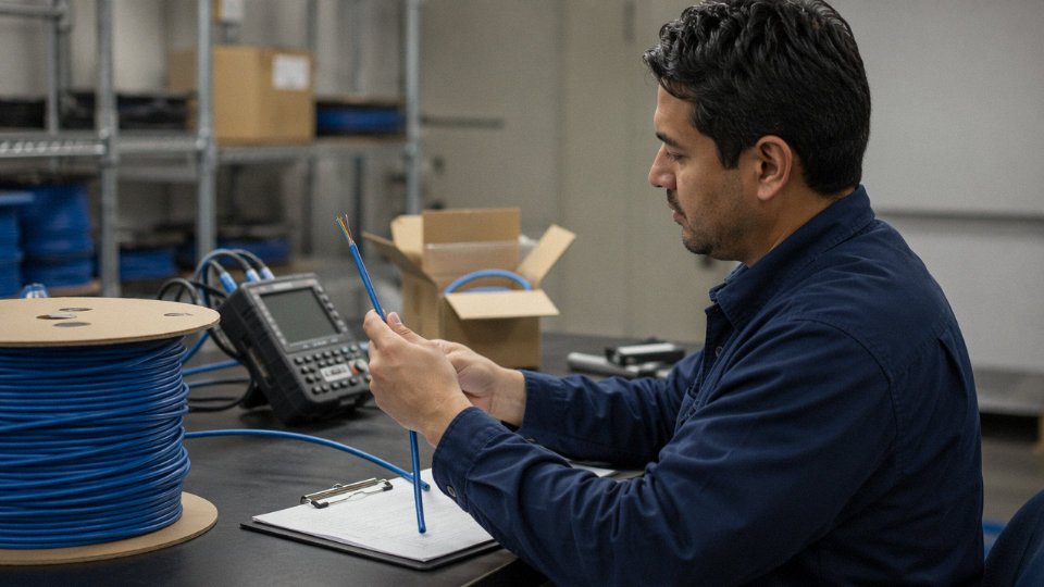
Finished reels go through a complete electrical test sequence: dielectric withstand, insulation resistance, wire map, and swept attenuation. Test records are tied to batch and shift via RFID tags on each reel — useful when a contractor calls six months after installation asking about a marginal link.
Jinda conducts inline spark testing at 2,000 V DC on every insulated Cat6 conductor before cablingTrue
Inline spark testing during conductor insulation is standard practice in IEC-compliant cable manufacturing and is the correct point to detect insulation faults before the cable is assembled and jacketed.
Supply and Logistics for International Orders
Standard Cat6 variants are available from 500 m reels for sample or small project orders. OEM jacket printing — custom labeling, sequential footage marking, private-label branding — is available from 10 km order quantities. Lead times run roughly 15–25 days for ex-stock configurations and 30–45 days for custom jacket compounds or non-standard color sequences. Both Qingdao and Shanghai ports handle FCL shipments to major global hubs; the export team can provide FOB, CIF, or DAP pricing depending on the destination and incoterms preference.
Documentation support for CE, UL, and country-specific import compliance is handled by a dedicated export technical team, which is worth mentioning because customs documentation errors on cable shipments — wrong HS code, missing RoHS declaration, absent test certificate — are one of the more common causes of port delays on large infrastructure projects. Getting that paperwork right the first time is part of the service.