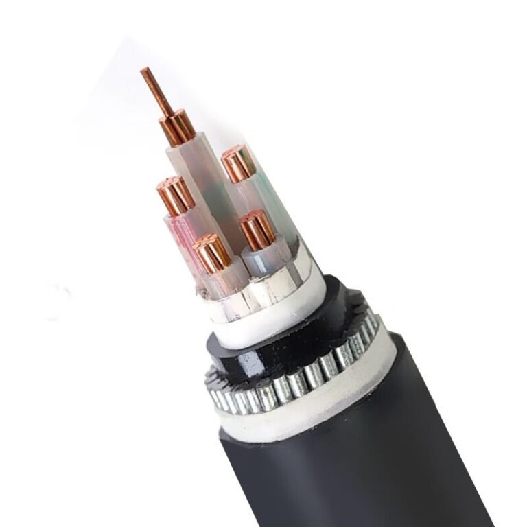
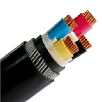
Specify the wrong cable type on a purchase order — or let a site electrician substitute “something similar” from the storeroom — and the consequences land fast: insulation breakdown under load cycling, ground faults that trip an entire production line, or a transformer that runs hot because the feeder conductor was undersized for its actual operating temperature. Warranty claims won’t cover installation errors, and in a heavy industrial facility the unplanned downtime from a single cable failure can easily outrun the original material cost within hours. The fix isn’t complicated, but it starts with understanding that “cable” is not one thing.
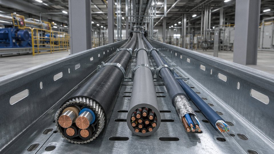
The four main types of cables are power cables, control cables, instrumentation cables, and communication (data/signal) cables. Each category is defined by its voltage rating, conductor configuration, shielding requirements, and the environment it’s designed to operate in — and substituting one type for another, even temporarily, routinely causes insulation failure, signal interference, or code violations.
What makes this more nuanced in practice is that the boundaries between categories shift depending on who you ask — a utility engineer and an automation integrator will draw the lines differently, and procurement teams often find that manufacturer datasheets use overlapping terminology that obscures real functional differences. The global cable market sat at roughly USD 225 billion in 2023 and is tracking toward USD 300 billion by 2030, which means an enormous volume of cable is being specified, bought, and installed every year — a lot of it incorrectly. The four-category framework that follows is the most operationally useful way to cut through that confusion.
Power Cables: Construction, Voltage Classes, and Load-Carrying Specifications
Power cables exist to move electrical energy — reliably, safely, and without burning down the building or tripping a substation. They carry the highest stakes of any cable category: a misspecified control cable causes a nuisance fault; a misspecified power cable causes a fire, a fatality, or months of unplanned downtime. That asymmetry is why the selection process deserves more rigor than most projects actually give it.
Voltage Classes and the Standards That Define Them
The IEC framework divides power cables into three broad voltage classes. Low voltage covers everything up to 1 kV — the workhorse of industrial plants and commercial buildings, governed primarily by IEC 60502-1. Medium voltage spans 1 kV to 36 kV, covering distribution feeders inside industrial campuses, wind farms, and utility substations, under IEC 60502-2. High and extra-high voltage starts above 36 kV, running up to 500 kV and beyond for transmission-class cables, where IEC 60840 and IEC 62067 apply. The jump from MV to HV is not incremental — the engineering complexity, testing requirements, factory qualification, and installation tolerances all change category, not just degree.
IEC 60502 governs both LV and MV power cables in most international markets outside North AmericaTrue
IEC 60502-1 applies to cables rated up to and including 1 kV; IEC 60502-2 covers cables from 1 kV to 30 kV, with some national annexes extending application to 36 kV. The NEC (NFPA 70) serves as the parallel framework in the United States and parts of Latin America.
Conductor Design: More Than Just a Wire
Conductor choice drives cost, weight, and installation flexibility more than any other single variable. Copper dominates in LV and MV industrial applications — roughly 60–65% of global cable shipments by value use copper conductors — because of its higher conductivity, easier termination, and better mechanical resilience at small cross-sections. Aluminum takes over in high-voltage overhead transmission, accounting for 70–80% of installed line length globally, largely because the weight and cost penalty of copper becomes prohibitive at large conductor sizes.
Cross-section geometry matters too. Circular stranded conductors are standard for flexible installations and smaller sizes. Sector-shaped conductors appear in multicore MV cables — three sectors pack more tightly than three circles, reducing overall cable diameter and sheath material cost. For a practical benchmark: a 240 mm² XLPE copper cable at 400 V can typically carry around 430 A in free air, though that figure shifts depending on ambient temperature, grouping, and installation method. Derate it to 45°C ambient with three cables touching and you might be looking at 320–350 A — a real difference that trips up engineers who copy ratings from a datasheet without reading the footnotes.
Insulation Systems: Thermal Rating Is the Key Variable
PVC insulation is cheap, widely available, and adequate for most LV general-purpose applications, but its continuous operating limit of 70°C becomes a constraint the moment you’re running high-load circuits in warm cable trays. XLPE (cross-linked polyethylene) handles 90°C continuous service and offers better dielectric strength at MV and HV, which is why it’s become the default for anything above a few kilovolts. EPR (ethylene propylene rubber) fills a specific niche — flexible cables, marine and offshore environments, and applications requiring ozone resistance — where XLPE’s relative stiffness creates a handling problem.
Don’t mix insulation types carelessly in a derating calculation. A PVC-insulated cable bundled with XLPE cables gets derated to PVC limits, not XLPE.
Armoring Options and When Each Actually Applies
| Armor Type | Typical Application | Key Advantage | Watch Out For |
|---|---|---|---|
| Steel Wire Armor (SWA) | Direct burial, industrial trenches | High tensile and crush resistance | Adds weight; magnetic losses on single-core AC cables |
| Steel Tape Armor (STA) | Fixed installations, moderate mechanical risk | Lower cost than SWA | Less crush resistance; not for pulling through conduit |
| Aluminum Wire Armor (AWA) | Single-core MV/HV cables | Non-magnetic — eliminates eddy current losses | Lower tensile strength than SWA; softer in rocky soil |
Single-core cables are a specific trap: SWA on a single-core AC cable creates a shorted magnetic loop. The induced eddy currents generate measurable heat and efficiency loss. AWA or non-magnetic armor is the correct specification here — it’s a well-known issue, yet wrong specs still show up on purchase orders.
Sheathing and Fire Performance
The outer sheath is the cable’s last line of defense, and increasingly it has to prove itself under fire conditions. Standard PVC sheathing satisfies basic mechanical and moisture protection requirements, but burns and releases HCl gas — a serious problem in enclosed spaces. LSZH (low smoke zero halogen) sheathing, sometimes labeled LSOH or LS0H depending on the standard, is now mandated in tunnels, public buildings, offshore platforms, and rail infrastructure in most European and Gulf region projects. IEC 60332 series covers flame retardancy; IEC 61034 tests smoke density. Both are increasingly written into project specifications as hard requirements, not options.
Polyethylene outer sheaths appear mainly in HV cables where UV resistance, water resistance, and low dielectric constant matter more than flame performance — typically in submarine or direct-burial transmission applications.
Practical Sizing: A Decision Sequence
Selecting the right cross-section is not a single lookup. The process runs in sequence:
- Calculate design load current from actual connected load and power factor — not connected load alone.
- Apply ambient temperature correction factor (tables in IEC 60364-5-52 or manufacturer datasheets) based on installation environment.
- Apply grouping derating if multiple cables run together; even two touching cables reduce rating by roughly 15–20%.
- Check voltage drop at full load over the actual circuit length. IEC and most national standards allow 3–5% maximum voltage drop from source to final load, though sensitive equipment often needs tighter limits.
- Verify the selected size against short-circuit withstand — the conductor must survive prospective fault current for the clearing time of the upstream protection.
Miss step five and you may pass every steady-state check, only to have the conductor melt during a fault before the breaker opens. It happens more often than it should, particularly on MV feeders sized by LV habits.
Control Cables: Signal Integrity, Multi-Core Design, and Automation System Integration
Control cables get misspecified more often than any other cable type on industrial projects. The usual mistake: an engineer pulls the power cable spec sheet, copies the conductor sizing logic, and ends up with overbuilt, expensive wiring that still fails to meet the signal integrity requirements that actually matter in a PLC cabinet. Power cables move energy. Control cables move intent — commands, interlocks, feedback pulses, alarm states — and the engineering priorities are almost inverted.
What Control Cables Actually Do and Where They Live
Operationally, control cables carry low-current signals, typically well under 5 A, at working voltages between 300 V and 600 V AC/DC. They connect motor control centers to field devices, PLCs to actuators, transmitters to DCS marshalling panels, and safety relays to trip circuits. In a refinery or a cement plant, hundreds of these runs share cable trays with 415 V and 6.6 kV power feeders — which is precisely where the interference problems start.
The distinction from power cables isn’t just current level. It’s function. A 1.5 mm² control core carrying a 24 V DC interlock signal to a solenoid valve is not a small power cable. It’s a logic pathway, and its reliability requirement is closer to an instrument cable than to a load feeder.
Core Count: Why Bundling Matters at Scale
Control cables are manufactured in multi-core configurations from as few as 2 cores up to 37-, 52-, or even 61-core assemblies. The economic and logistical argument for higher core counts is straightforward once you’ve done a large installation.
Consider a realistic scenario: a mid-size automated packaging line requiring roughly 240 discrete control signals between a remote I/O panel and a centralized MCC — start/stop commands, valve feedback, motor status, e-stop loops, and the like. Running those signals as individual 2-core cables means somewhere between 120 and 130 separate cable pulls, conduit fill problems, 240+ individual gland entries on the panel, and a commissioning team spending days just on cable identification. Switch to a combination of 24-core and 37-core control cables, and you might reduce that to 7 or 8 cable runs. Conduit fill drops dramatically, installation labor shrinks, and the marshalling panel interior actually remains legible after commissioning.
The trade-off is flexibility during modifications — adding a signal to an existing 37-core cable that’s already at capacity means a new run anyway. On stable, well-defined systems, higher core count wins. On plants with frequent process changes, building in spare cores (typically 10–15% extra) matters more than absolute core count.
Shielding Configurations and EMI: Not All Screens Are Equal
In shared cable trays carrying both control and power cables — which is the reality in most factories, regardless of what the design drawings intended — electromagnetic interference pickup is a real failure mode, not a theoretical one. Unshielded control cables in close proximity to variable frequency drives are a particular problem; VFDs generate significant high-frequency conducted noise, and the switching transients can corrupt 4–20 mA loops or produce phantom digital signals.
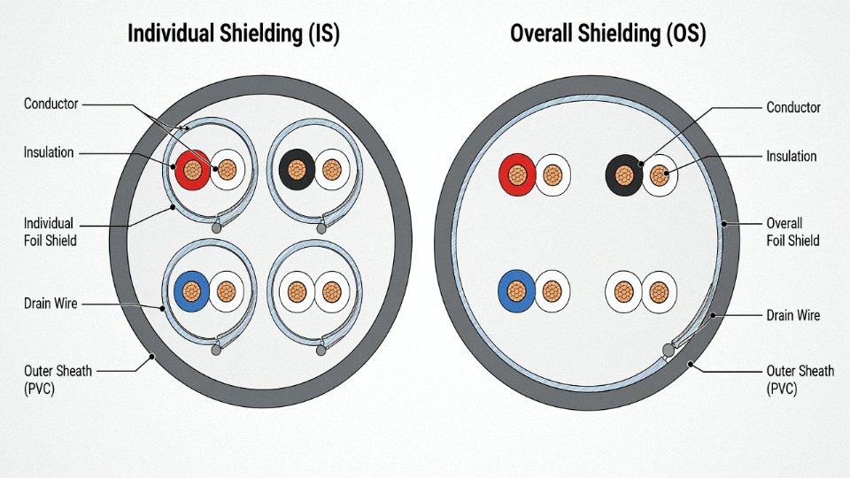
Three shielding configurations address this in different ways:
| Configuration | What it does | Best for |
|---|---|---|
| Overall screen (OS) | Single foil or braid over all cores | General EMI reduction in moderate-noise environments |
| Individually screened pairs (IS) | Each pair shielded separately | Crosstalk-sensitive analog signals, long runs |
| IS + OS combined | Both layers | High-interference environments, VFD-heavy plants, marine applications |
The IS+OS configuration is standard in offshore and marine installations governed by IEC 60092 and EN 50288, where cable trays are tightly packed and noise sources are unavoidable. For process plant analog loops running 200 m or more, individually screened pairs are worth the added cost — crosstalk between unshielded pairs over long runs can easily produce errors that exceed the loop’s accuracy specification.
Conductor Cross-Section Selection: Smaller Is Usually Right
Control cable conductors are most commonly specified at 0.5 mm², 0.75 mm², 1.0 mm², 1.5 mm², or 2.5 mm². In most control circuits, the limiting factor is not current-carrying capacity — a 24 V DC signal line draws milliamps — but voltage drop over distance and terminal compatibility. A 1.0 mm² conductor is adequate for the overwhelming majority of PLC I/O wiring up to 100 m or so; 1.5 mm² covers most longer runs comfortably.
Specifying 2.5 mm² throughout a control system because “it’s safer” doesn’t improve performance. It adds weight, increases conduit fill, makes termination harder in standard 2.5 mm² cage clamp terminals, and adds material cost that compounds across hundreds of cores. In practice, I’ve seen projects where blanket over-specification of control cable conductor size added 12–18% to cable procurement cost with zero functional benefit.
Color Coding and International Commissioning Reality
Multi-core control cables with more than a handful of cores depend entirely on reliable color coding or numbered identification for accurate termination. IEC 60227 and VDE 0293 define standard color sequences for multi-core cables, and following them matters on multinational projects where the installation team, the commissioning engineer, and the panel builder may all be working from documentation in different languages. A consistent, standard color sequence means a technician can terminate core 18 of a 24-core cable correctly by color-and-number matching alone, without needing to read the cable schedule.
Jinda's multi-core control cables conform to ICEA, BS 5308, and IEC 60502-1 standards, with manufacturing controls that maintain consistent capacitance per unit length across production runs.True
Consistent capacitance per unit length is a critical parameter in long control cable runs used in process control, as variation affects signal transmission characteristics and loop stability. This is a verifiable manufacturing quality parameter, not a marketing claim.
Capacitance consistency is one of those parameters that rarely shows up in basic procurement specs but matters considerably on long cable runs — typically anything beyond 300–400 m — in process control applications. If capacitance per meter varies between drum lengths on the same project, analog signal behavior changes between segments, and what should be a clean 4–20 mA loop develops offsets that are frustrating to diagnose. Getting this right requires tight process control in the extrusion and stranding stages, not just end-of-line testing.
Instrument and Signal Cables: Measurement Accuracy, Low-Level Signal Transmission, and Noise Rejection
Instrument cables are where the physics gets unforgiving. A control cable carrying a 24 V DC discrete signal can tolerate a few ohms of extra resistance and still trip a relay cleanly. An instrument cable carrying a 4–20 mA analog signal from a pressure transmitter — or worse, a Type K thermocouple output measured in microvolts — has no such margin. Signal corruption at this level doesn’t announce itself with a blown fuse or a tripped breaker. It shows up as a temperature reading that’s consistently 3°C high, a flow totalizer that drifts, a batch that fails QC. By the time someone traces it to the cable, the process has already been running on bad data.
How Instrument Cables Differ from Control Cables
The distinction is not primarily about voltage rating or physical size — it’s about signal level and noise susceptibility. Control cables, as covered earlier in this article, typically carry 24 V DC digital signals or 120/240 V AC command circuits where a millivolt of noise is irrelevant. Instrument cables operate in ranges where noise is the signal if you’re not careful: 4–20 mA current loops, 0–10 V DC analog outputs, RTD circuits where even 0.1 Ω of unexpected conductor resistance introduces a real, calculable temperature error (for a Pt100, that’s roughly 0.25–0.26°C per 0.1 Ω — not trivial in pharmaceutical or custody-transfer applications), and thermocouple circuits where the full-scale EMF for a Type K pair across 0–1000°C is only about 41 mV total.
Thermocouple Extension vs. Compensating Cable — A Common and Costly Mistake
Using a compensating cable instead of an extension cable for a Type K thermocouple introduces measurement error that increases significantly above roughly 60°C ambient at the cable junction.True
Compensating cables use copper-based alloys engineered to approximate the thermocouple EMF output only within a limited temperature range, typically 0–60°C or 0–100°C depending on grade. Extension cables use the same alloys as the thermocouple itself (Chromel-Alumel for Type K), maintaining accurate EMF compensation across the full thermocouple operating range. Misapplication is a documented source of systematic measurement offset in industrial installations.
Extension cables use the identical alloy pair as the thermocouple — Chromel-Alumel for Type K, Iron-Constantan for Type J. Compensating cables use copper-based approximations that hold accuracy only within a restricted ambient temperature window, often 0–60°C. In a cable tray running through a hot utility corridor or near furnace walls where ambient cable temperatures can reach 70–90°C, a compensating cable substituted for an extension cable will produce a systematic offset error. The instrument reads confidently wrong. This mistake is surprisingly common during maintenance replacements when the original cable type isn’t documented.
Physical Construction That Makes Instrument Cable Work
The construction features aren’t arbitrary. Each one addresses a specific noise mechanism:
Twisted pairs with a defined lay length (pitch typically 25–50 mm, shorter for higher-frequency rejection) cancel magnetically induced noise by ensuring that adjacent conductors intercept equal and opposite flux from external fields like motor drives and power cables running in parallel trays.
Individual foil shields (aluminized polyester) with a continuous drain wire provide electrostatic shielding — they block capacitively coupled noise from high-voltage conductors nearby. Braid shields offer slightly lower transfer impedance at higher frequencies and are preferred in environments with strong RF sources, though foil is the more common choice for standard 4–20 mA and thermocouple runs given its lighter weight and easier termination.
Low conductor capacitance — typically held below 100 pF/m conductor-to-screen, and ideally below 60–80 pF/m for intrinsically safe circuits — matters because capacitance limits the maximum cable length permissible within IS barrier constraints.
Conductor gauge in the 18–24 AWG range (roughly 0.5–1.5 mm²) reflects a balance: heavy enough for acceptable loop resistance over long field runs, light enough to keep capacitance low.
Grounding: One End Only, and It Matters Which End
Instrument cable shields must be grounded at one end only — almost universally the control room or marshalling panel end. Ground both ends and you create a loop antenna. Any difference in ground potential between field and control room (which exists in virtually every real plant, usually in the range of 0.5–5 V at 50/60 Hz depending on how well the earthing system is maintained) drives a circulating current through the shield. That current induces a voltage in the signal conductors through mutual inductance. The result is 50 or 60 Hz noise directly on the measurement signal. In practice, a DCS analog input with a ±10 mV noise floor becomes unusable for signals requiring ±0.5% accuracy.
Hazardous Area Installations: ATEX, IECEx, and Capacitance Limits
In Zone 0, Zone 1, and Zone 2 classified areas — petrochemical plants, offshore platforms, pharmaceutical solvent handling — instrument cables connected to intrinsically safe circuits must comply with capacitance and inductance maximums set by the IS barrier manufacturer. These aren’t guidelines; exceeding them means the barrier can no longer guarantee the circuit is incapable of igniting an explosive atmosphere. Typical Zener barrier specifications limit total cable capacitance to 83–150 nF and inductance to 1–4 mH depending on voltage and current rating. This directly caps maximum cable run length for a given cable construction. A cable with 100 pF/m capacitance hits a 150 nF barrier limit at 1,500 m — but a poorly specified cable at 200 pF/m caps out at 750 m, which may fall short of field instrument locations in a large processing unit.
Signal Type Comparison: Cable Requirements at a Glance
| Signal Type | Typical Level | Max Recommended Capacitance | Shield Type | Key Specification Risk |
|---|---|---|---|---|
| 4–20 mA current loop | 4–20 mA / 1–5 V | ≤100 pF/m (IS: ≤60 pF/m) | Foil + drain | Ground loop, IS capacitance limit |
| Thermocouple Type K | 0–41 mV (0–1000°C) | ≤100 pF/m | Foil + drain | Wrong cable alloy, cold junction error |
| Thermocouple Type J/T | 0–57 mV / 0–20 mV | ≤100 pF/m | Foil + drain | Same alloy substitution risk |
| RTD Pt100 (3-wire) | ~100–380 Ω | ≤100 pF/m | Foil + drain | Lead resistance imbalance, moisture ingress |
| 0–10 V DC | 0–10 V | ≤150 pF/m | Foil or braid | Source impedance mismatch, common-mode noise |
| Pulse/frequency | 0–24 V, up to ~100 kHz | ≤80 pF/m | Braid preferred | Signal edge distortion, cross-talk from adjacent pairs |
The table simplifies somewhat — actual limits depend on run length, source impedance, and whether IS certification applies. But the directional logic holds: lower signal levels and longer runs demand tighter capacitance control and more disciplined shielding practice.
Communication and Data Cables: Structured Cabling, Industrial Ethernet, and Fiber Optics
Communication and data cables are the fourth type — and probably the most diverse. A Cat6 patch cable in a server room and a PROFINET cable running through a robotic welding cell are both “data cables,” but they share almost nothing in terms of construction requirements or what happens when you spec the wrong one.
Copper Structured Cabling: Categories, Bandwidth, and What the Numbers Actually Mean
The TIA/EIA-568 and ISO/IEC 11801 standards define copper data cable performance in categories most engineers recognize: Cat5e through Cat8. Cat5e supports 100 MHz bandwidth and handles 1 Gb/s reliably at runs up to 100 m — still perfectly adequate for a lot of building LAN work. Cat6 and Cat6A push to 250–500 MHz and support 10 Gb/s. Cat8 reaches 2000 MHz and can carry 25–40 Gb/s, though only over short runs, typically 30 m or less, which limits it to data center spine applications rather than general horizontal cabling.
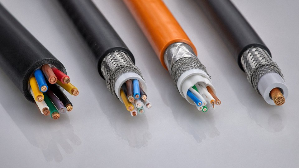
The shielding nomenclature trips people up. UTP is unshielded twisted pair; F/UTP has an overall foil wrap around all pairs; S/FTP has both an overall braid shield and individual foil-wrapped pairs. For office environments, UTP Cat6A usually suffices. Drop that same cable into a panel room next to a row of variable frequency drives and you’ll see bit errors almost immediately. The physics is straightforward — VFDs generate significant common-mode noise in the 10–100 kHz range, and unshielded data cables make decent antennas at those frequencies.
Industrial Fieldbus and Ethernet Cables: Where IT Specs Break Down Fast
PROFIBUS, PROFINET, EtherCAT, DeviceNet, CANopen — these protocols each have published cable specifications, and the physical cable requirements go well beyond anything TIA-568 demands. A cable running in a drag chain on a CNC gantry might flex 5–10 million cycles over its service life. Standard office patch cable fails in months under that kind of mechanical stress, because the conductors work-harden and crack. Proper industrial Ethernet cable uses stranded conductors with a high strand count, a polyurethane or TPE outer sheath rated for oils and cutting fluids, and a tested flex life certified to IEC 61076-2 or equivalent. Operating temperature range matters too — a cable installed near a furnace exhaust or in an outdoor Nordic installation needs to stay functional from roughly -40°C up to +90°C.
Shielding on industrial fieldbus cables isn’t optional. The shield needs to be terminated correctly at the panel end — floating it at one end to avoid ground loops is standard practice, though which end depends on your specific system architecture. A poorly terminated shield is sometimes worse than no shield at all because it can act as a ground loop antenna.
Fiber Optic Cables: EMI Immunity and the Distance Problem Solved
When copper genuinely can’t do the job, fiber is the answer. Single-mode fiber (OS1/OS2, 9/125 µm core/cladding geometry) supports transmission distances up to roughly 80 km without amplification — used in utility substation interconnects and campus backbone runs. Multimode fiber (OM3 through OM5, 50/125 µm) is cheaper to terminate and works well for data center or inter-building links up to around 300–400 m at 100 Gb/s. OM5 extends that to support 400 Gb/s applications over short distances using wavelength-division multiplexing.
The decisive advantage in industrial settings is complete EMI immunity. Fiber carries light, not current, so a high-voltage switchyard, an MRI suite, or a petrochemical plant with extensive VFD infrastructure can run fiber right alongside power conductors without any signal degradation. That’s not a theoretical benefit — it’s the reason high-voltage substations almost universally specify fiber for protection relay communications.
Governing standards here are IEC 60793 (optical fiber specifications) and IEC 60794 (cable construction), with IEEE 802.3 covering the Ethernet physical layer requirements. Buyers should demand test reports referencing these standards on purchase orders, not just catalog claims — counterfeit or substandard fiber cable that meets visual inspection but fails insertion loss requirements is a real procurement risk, particularly on large infrastructure projects sourced through multiple tiers.
Fiber optic cables are immune to electromagnetic interference because they transmit data as light pulses rather than electrical signalsTrue
Optical fiber carries photons, not electrons, so there is no conductive path for electromagnetic fields to induce noise. This is a well-established physical principle confirmed by IEC 60793/60794 standards and is the primary reason fiber is specified in EMI-intensive environments such as high-voltage substations and MRI facilities.
Hybrid Cables and Industry 4.0 Demands
One increasingly common requirement is the hybrid cable — a single jacket combining power conductors and shielded data pairs. Collaborative robots, smart servo systems, and IIoT sensors increasingly need both power and communication in one cable for routing simplicity and reduced conduit fill. The engineering challenge is crosstalk isolation: the power conductors need individual shielding, and the data pairs need their own, with careful attention to the dielectric separation between them. Done right, a well-designed hybrid cable meets both the mechanical flex requirements of a drag chain and the signal integrity requirements of, say, EtherCAT at 100 Mb/s. Done poorly, you get intermittent communication faults that are genuinely difficult to diagnose because they only appear under load.
Jinda’s communication cable range covers industrial Ethernet cables, PROFIBUS-compliant fieldbus cables, and armored fiber optic assemblies designed for outdoor and substation deployment. Products carry CE, UL, and RoHS certifications — which matters on international project bids where a single non-compliant cable type can hold up customs clearance or fail a site inspection, either of which costs more in delay than the cable itself.
How to Select the Correct Cable Type: A Step-by-Step Engineering Decision Process
Getting the cable type wrong on a project isn’t just an inconvenience — it usually means a change order, a delay waiting on replacement stock, or in worse cases, a safety non-conformance that holds up commissioning. The four-type taxonomy only has value if you can translate it into a purchase specification. Here’s how to do that systematically.
Step 1 — Define the Circuit Function First
Before anything else: what is this cable actually doing? Carrying kilowatts to a motor? Transmitting a 4–20 mA signal from a pressure transmitter back to a DCS? Sending open/close commands to a motorized valve? Running Profinet between a PLC and a remote I/O rack?
That single question eliminates three of the four cable types immediately. In practice, a surprising number of specification errors happen because someone on site grabs “a cable” without answering this question — usually because the original BOM was ambiguous. Instrument cables specified as control cables is the most common example I’ve seen, and it shows up as measurement drift and noise complaints within the first few months of operation.
Step 2 — Nail Down Voltage, Current, and Signal Parameters
For power cables, you need the rated system voltage expressed as Uo/U (e.g., 0.6/1 kV), maximum continuous load current, and the prospective short-circuit current at the cable origin — this last figure drives the minimum conductor cross-section from a thermal withstand perspective, which often overrides the ampacity calculation entirely on short feeder runs close to large transformers.
For instrument cables, the relevant parameters are signal voltage (typically millivolt range for thermocouples, 1–5 V or 4–20 mA for transmitters), maximum allowable loop resistance, and whether the signal is single-ended or differential. For communication cables, you need operating frequency, characteristic impedance (100 Ω for Cat6 Ethernet, 120 Ω for RS-485 fieldbus, typically), and maximum segment length.
Step 3 — Map the Installation Environment
Outdoor direct burial calls for a different construction than cable tray inside a clean control room. The environment determines insulation material (XLPE vs. PVC vs. EPR), jacket compound (PVC, PE, CPE, polyurethane for continuous flex), armor type (SWA for static runs, fine-wire braided armor for moving applications), and shielding requirements. UV exposure eliminates standard black PVC jacket compounds in some climates — sunlight degrades plasticizers faster at high altitudes or in tropical conditions, sometimes within three to five years rather than the expected fifteen to twenty.
If the cable enters a Zone 1 or Zone 2 hazardous area, you are no longer just selecting a cable — you are selecting a cable that must be compatible with a certified gland, conduit seal, or cable transit that forms part of a certified assembly. Specifying the cable in isolation without considering the termination system is a classic gap that shows up during ATEX audits.
Step 4 — Confirm the Applicable Standards and Fire Class
This varies significantly by geography and end-user. IEC 60502 covers power cables up to 30 kV; IEC 60227 and 60245 cover flexible and rubber cables; IEC 60332 series and EN 50575 (CPR) govern fire performance. For a project shipping to Australia, AS/NZS 5000 applies. For North America, NEC Article 310 and UL listings drive conductor sizing and jacket requirements. Know which standard governs before you write the cable schedule — otherwise you end up specifying an IEC product into a UL-only jurisdiction and finding out at factory acceptance test.
Fire performance class (Eca through Aca under CPR, or LSZH/LSHF compound requirement) is increasingly specified by end-users even when not strictly mandatory. Get this confirmed early; it affects jacket compound selection and typically adds 8–20% to cable unit cost depending on the product family.
Step 5 — Calculate Cross-Section and Verify Voltage Drop
Here’s a worked example. A 75 kW, 400 V three-phase motor, power factor 0.85, efficiency 0.93, in a 35 °C ambient environment, cables grouped in a tray with five other loaded circuits, 120 m run.
Full-load current: 75,000 ÷ (√3 × 400 × 0.85 × 0.93) ≈ 137 A. Starting from IEC 60364-5-52 Table B.52.4 (trefoil, single-layer tray, XLPE insulation), a 50 mm² copper conductor carries roughly 170 A at 30 °C reference. Apply ambient correction for 35 °C (factor ≈ 0.96) and grouping correction for six circuits (factor roughly 0.72 for a full tray) — derated capacity ≈ 170 × 0.96 × 0.72 ≈ 118 A. That’s undersized. Step up to 70 mm²: base 210 A, derated ≈ 145 A. That clears 137 A with a reasonable margin.
Voltage drop check: for 70 mm² copper at 137 A over 120 m (one-way), using IEC 60364 resistance/reactance figures (approximately 0.32 mΩ/m per conductor at operating temperature), voltage drop ≈ 1.73 × 137 × 0.32 × 10⁻³ × 120 ≈ 9.1 V, or about 2.3% of 400 V. Within the typical 4% limit for motor feeders. If the run were 200 m, you’d be over that limit and would need 95 mm² — which is the kind of thing that gets missed when engineers copy cross-sections from a similar project without re-running the drop calculation for the actual run length.
Decision Matrix: Circuit Function to Cable Specification
| Circuit Function | Environment | Regulatory Context | Cable Type | Insulation / Jacket | Armor | Key IEC Standard |
|---|---|---|---|---|---|---|
| Power, LV (≤1 kV) | Indoor cable tray | IEC, CPR Cca | Power cable | XLPE / PVC | None or DSTA | IEC 60502-1 |
| Power, LV (≤1 kV) | Direct burial, outdoor | IEC | Power cable | XLPE / HDPE | SWA or double steel tape | IEC 60502-1 |
| Power, MV (1–36 kV) | Underground, outdoor | IEC | Power cable | XLPE / PE | AWA or lead sheath | IEC 60502-2 |
| Control (24 VDC–110 VAC) | Indoor, cable tray | IEC, LSZH required | Control cable | PVC or LSZH / LSZH | None or SWA | IEC 60227 / 60228 |
| Analog instrument (4–20 mA) | Industrial, mixed routes | IEC | Instrument cable | PTFE or PE / PVC | OS (overall screen) | IEC 60544 (env.) |
| Digital data, industrial | Outdoor, EMI-heavy | IEC 61784 | Fieldbus cable | PE / PUR | Foil + drain wire | IEC 61156 |
| Data, structured cabling | Indoor IT / OT | TIA-568, EN 50173 | Cat6A U/FTP | LSZH | None | IEC 61156-5 |
| Fiber optic, long haul | Outdoor burial | ITU-T G.652 | OS2 single-mode | PE outer sheath | Steel wire armor | IEC 60794-1 |
The matrix above isn’t exhaustive — every real project will have at least one line item that doesn’t map cleanly to a standard row. But working through these five steps in sequence, rather than jumping straight to a cross-section lookup table, is what separates a cable schedule that sails through engineering review from one that generates forty RFIs before procurement closes.
Key International Standards, Testing Requirements, and Quality Certifications Buyers Must Verify
Sourcing cables across borders without verifying the right standards documentation is one of the faster ways to create a compliance disaster on a major project. It happens more than most procurement teams want to admit — a shipment clears customs, gets pulled out during site inspection, and suddenly you’re negotiating emergency replacements on a construction schedule that has no slack. Understanding exactly which standards apply to which cable type, and what those standards actually require, is the practical defense against that scenario.
IEC Product Standards: What They Actually Specify
IEC 60502 governs extruded solid dielectric insulated power cables from 1 kV up to 30 kV — and what it specifies is worth understanding in concrete terms, not just as a number you quote on a datasheet. It defines minimum insulation thickness by voltage class and conductor cross-section, dimensional tolerances on the overall diameter, and critically, the high-voltage test levels (typically a 4 kV to 10.5 kV AC withstand test depending on rated voltage, applied for 5 minutes on finished cable lengths). Conductor DC resistance limits are cross-referenced to IEC 60228, which means a cable marked “IEC 60502” that ships with conductors failing the Class 2 resistance limits is technically non-conforming even if the insulation looks fine.
IEC 60227 and IEC 60245 cover PVC and rubber insulated cables respectively — the bread-and-butter wiring used in building services, control panels, and light industrial equipment. IEC 60092 applies specifically to marine cables, with more demanding requirements for flame retardancy, oil resistance, and mechanical robustness suited to shipboard environments. For data cables, IEC 60189 sets transmission performance parameters for low-frequency analog types, while IEC 60793 and IEC 60794 govern optical fiber and fiber optic cable construction — covering attenuation coefficients, bandwidth, and tensile and crush load limits that vary significantly between tight-buffered and loose-tube designs.
Fire Performance Testing: The Bundle Test Is What Matters
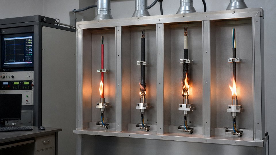
Single-cable flame tests (IEC 60332-1) are not particularly demanding. A cable can pass 60332-1 and still be a liability in a cable tray running through an equipment room. The bundle flame test under IEC 60332-3 — specifically Category A, B, or C depending on total combustible material per meter of cable tray — is the relevant specification for any installation where multiple cables run together. The difference in burning behavior between those two test configurations is dramatic, and some suppliers will quote 60332-1 compliance without volunteering that they haven’t tested to 60332-3.
Halogen-free requirements are increasingly standard on infrastructure projects, especially in tunnels, rail, and offshore platforms. IEC 60754-1 and -2 measure acid gas emission during combustion; IEC 61034 measures smoke density. EN 50575 (the EU Construction Products Regulation framework for cables) introduces a reaction-to-fire classification from Aca down to Fca — and for EU project work, the CPR Declaration of Performance is a legal market access document, not optional paperwork.
Factory Quality Controls Buyers Should Require
Every drum shipped should come with a test report showing conductor resistance measurement, insulation resistance, and spark test results from an inline HV detector (typically 6–12 kV depending on insulation class). Requesting these as a standard part of your purchase order terms costs nothing and creates a paper trail that matters if a defect surfaces during the defect liability period. Third-party witness testing through SGS, Bureau Veritas, or Intertek on the first production batch of a new supplier relationship is worth the cost — usually a few hundred dollars per inspection visit against a contract value that might run to hundreds of thousands.
Retain cable samples from each drum. A short section, properly labeled with the drum number, held for the duration of the defect liability period, is the physical evidence that resolves disputes. Without it, arguments about conductor cross-section or compound quality become difficult to settle.
The Counterfeiting Problem Is Real and Documented
Undersized conductors are a documented and widespread quality problem in the global cable industry, where cables marked as 16 mm² have been measured at actual cross-sections below 14 mm².True
Independent testing by certification bodies and utility incoming inspection programs in multiple countries has confirmed that conductor cross-section shortfalls are among the most common non-conformances found in low-cost cable imports. A 16 mm² conductor running at 13–14 mm² actual area has meaningfully higher resistance, higher operating temperature, and lower current-carrying capacity than specified.
Beyond undersized conductors, the other failure modes seen in incoming inspection include aluminum conductor cores wrapped in a thin copper cladding to pass visual inspection, and recycled PVC insulation compounds that fail cold-bend tests at -15°C — which matters the moment those cables go into an outdoor installation in a northern climate. Detection requires cross-sectional measurement (weigh a one-meter sample and calculate from density), X-ray fluorescence on conductor material, and cold-bend testing on samples from actual delivered drums, not just the manufacturer’s test certificates.
Market Access Certifications
CE marking under EU directives, UL listing for North American projects, RoHS compliance (restricting lead, cadmium, hexavalent chromium, and certain brominated flame retardants), and REACH declarations covering substances of very high concern — these are progressively becoming mandatory across EU, Gulf Cooperation Council, and ASEAN project specifications. For GCC projects in particular, SASO and ESMA approvals are increasingly enforced at the border rather than left as a contractual formality.
Jinda’s manufacturing operations are certified to ISO 9001, with in-house high-voltage test laboratory capacity covering routine and type tests across the product range. Conductor resistance is verified on every drum before shipment, and the traceability system links each cable drum to raw material batch records — the copper rod heat number, the insulation compound lot, the armoring wire batch. For multinational EPC contractors running ITP (Inspection and Test Plan) requirements, that batch-level traceability is what allows a non-conformance to be isolated to specific drums rather than triggering a full-shipment rejection.
Frequently Asked Questions About the 4 Types of Cables
Can a control cable be used as a power cable?
No — and this substitution causes real failures in the field, not just paperwork violations. Control cables are built for low-current switching signals, typically with conductor cross-sections of 0.5–2.5 mm² and insulation walls sized for 300/500 V or 450/750 V service at negligible sustained current. Put a 20 A motor feed through that conductor and the insulation runs hot, the conductor reaches thermal limits well below the circuit’s fault-current demand, and you’ve already voided the equipment warranty and your site’s insurance coverage before anything visibly fails.
IEC 60502 sets minimum insulation thickness and conductor sizing requirements for power circuits precisely because fault currents — which can be 10–20× rated current for the first few cycles — demand both thermal mass and dielectric strength that control cable construction simply doesn’t have. I’ve seen panels where an installer grabbed multi-core control cable because it was the right color or happened to be on the reel. The result was a smoldering terminal block three months later. Don’t do it.
What is the difference between an instrument cable and a control cable?
The distinction is about signal level, not just cable construction. Control cables typically carry 24 V DC switching logic or 240 V AC motor commands — currents in the 0.5–5 A range where a few millivolts of induced noise on the line makes no practical difference to a relay or PLC digital input.
Instrument cables carry thermocouple signals in the 10–50 mV range, 4–20 mA analog loops from pressure or flow transmitters, or RTD resistance signals at sub-ohm resolution. At those levels, even 2–3 mV of induced noise from a nearby VFD or power bus represents a 1–2% measurement error — which in a custody-transfer flow application or a SIL-rated safety loop is completely unacceptable. Instrument cables address this with individually shielded pairs, drain wires, and often an overall braid or foil shield. Running instrument wiring in the same tray as 480 V motor cables without separation defeats that shielding entirely, regardless of cable quality.
What is XLPE cable and why is it preferred over PVC for medium-voltage power cables?
XLPE (cross-linked polyethylene) runs continuously at 90°C conductor temperature versus 70°C for PVC, which means a given conductor cross-section carries more current — or you can specify one size smaller and save copper cost on long runs. Above roughly 3.3 kV, dielectric losses in PVC become meaningful and moisture absorption gradually degrades the insulation; XLPE resists both. Expected service life for XLPE MV cable in a properly installed underground system is 40 years or more, compared to 25–30 years for PVC in the same duty.
XLPE insulation is universally preferred over PVC for cables rated above 3.3 kV in modern industrial and utility installations.True
IEC 60502-2 and most major utility specifications default to XLPE for MV cables due to its superior thermal rating, lower dielectric loss factor, and moisture resistance. PVC is rarely specified above 1 kV in new installations.
How far can a data cable transmit a signal before requiring a repeater or switch?
It depends heavily on cable category, fiber type, and data rate — there is no single answer. Rough working figures:
| Medium | Data Rate | Max Segment Length |
|---|---|---|
| Cat6A copper | 10 Gb/s | 100 m (TIA-568) |
| Multimode OM4 fiber | 10 Gb/s | ~400 m |
| Multimode OM4 fiber | 100 Gb/s | ~150 m |
| Single-mode OS2 fiber | 10 Gb/s | up to 10 km unamplified |
| Single-mode OS2 fiber | 10 Gb/s | up to 80 km with matched transceivers |
| PROFIBUS DP copper | 12 Mb/s | 100 m |
| PROFIBUS DP copper | 9.6 kb/s | 1,200 m |
For industrial plants with long cable runs between buildings or substations, single-mode fiber is usually the practical answer — cost per meter has dropped enough that the distance advantage outweighs copper’s lower termination cost on anything over 200–300 m.
What does LSZH mean and when is it required?
LSZH stands for Low Smoke Zero Halogen. Standard PVC insulation, when it burns, generates dense black smoke and releases hydrogen chloride gas — both of which kill people in enclosed spaces and destroy nearby electronics. LSZH compounds are formulated to limit smoke density and eliminate halogenated combustion products.
It’s mandated, not optional, by BS 7671, IEC 60092-376 (marine), EN 50575, and most offshore platform specifications for any cable installed in tunnels, rail carriages, data centers, offshore topsides, or public buildings where evacuation is constrained. Specifying standard PVC in those environments to save a small cost premium is a decision that tends to look very bad after an incident.
How do I specify the right cable for a direct burial application?
Four things need to be right simultaneously: moisture-resistant insulation (XLPE or medium-density PE, not standard PVC), mechanical armor suited to the burial environment (steel wire armor for rocky soil, corrugated steel tape armor where rodent attack or light mechanical load is the main concern), an outer PE sheath that resists soil chemicals and groundwater, and compliance with IEC 60502-1 (LV) or IEC 60502-2 (MV) for the burial rating.
The step most engineers skip is measuring soil thermal resistivity before sizing the conductor. Wet clay and dry sand differ by a factor of 3–4 in thermal resistivity, which translates directly into derating the cable’s current-carrying capacity. Oversized cable in a poorly documented burial is expensive. Undersized cable in unexpectedly dry sandy soil runs hotter than rated and ages out early.
What is the minimum order quantity for Jinda cables on international export orders?
Jinda’s export model is flexible enough to handle both large infrastructure projects and more targeted procurement needs. For specialty cables — armored instrument cables, fire-resistant LV power cables, or custom multi-core control cables — standard export orders typically begin from one full drum per line item. For standard LV power and control cable ranges, container-load quantities are the normal entry point for most export pricing tiers, though exact MOQs shift depending on conductor cross-section, insulation type, and whether the order calls for factory witness testing or third-party inspection (SGS, Bureau Veritas, and similar).
Project-specific quotations, lead time estimates, and technical pre-qualification documentation are available through Jinda’s global sales team, which handles orders across more than 50 countries from five production bases in China.
Jinda’s Global Manufacturing Capability and How to Source All 4 Cable Types From a Single Supplier
Sourcing four distinct cable types from four different suppliers sounds manageable on paper. In practice, it multiplies your qualification workload, creates finger-pointing when an interface problem emerges on site, and almost guarantees some inconsistency in documentation formats when your QA team tries to compile a single handover package. There’s a real operational case for consolidating cable supply — provided the single supplier actually has the manufacturing depth to cover all four types without compromising on any of them.
Manufacturing Scale That Supports Multi-Type Projects
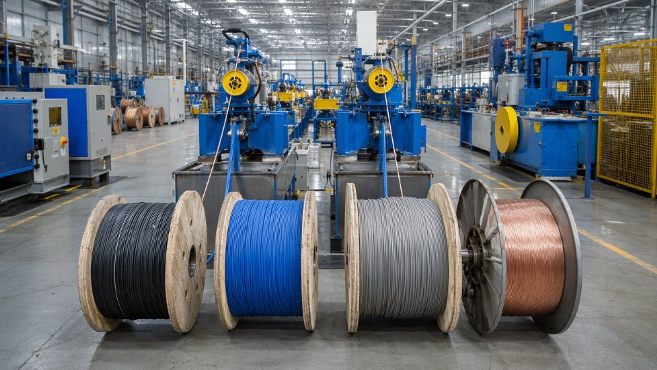
Jinda has been producing cables since 1987, which means the company has run through multiple industrial cycles — the move from paper insulation to XLPE, the expansion of industrial automation, the current wave of renewable energy projects — and adjusted its production infrastructure accordingly. Five production bases across China, totaling roughly 470,000 m² of manufacturing floor space and staffed by over 1,000 employees, gives a reasonable buffer against the capacity crunches that trip up smaller cable mills when a large EPC order arrives mid-cycle.
Scale matters for quality consistency, not just volume. When power cables, control cables, instrument cables, and industrial Ethernet cables all move through a unified quality management system, the test documentation, drum labeling, and certification formats are consistent across every cable type in the shipment. That sounds minor until you’re on site trying to reconcile four sets of drum test reports from four different mills, each formatted differently, each referencing a slightly different revision of the same IEC standard.
Product Range Across All Four Cable Types
The product portfolio runs from LV power cables in standard XLPE/SWA/PVC construction all the way to MV cables up to 35 kV. Control cable offerings extend to 61-core configurations — which covers most motor control center and marshalling cabinet applications without needing to special-order. Screened and individually screened instrument cables for process industries are available in both TC and RTD-type constructions. Industrial Ethernet, PROFIBUS, and fieldbus cables round out the communication and data side.
Beyond the four core types, there are armored direct burial cables, LSZH fire-resistant cables for tunnel and public building applications, and specialized constructions for mining (flexible trailing cables), marine environments, and wind and solar installations. For an EPC contractor who would otherwise qualify five or six suppliers to cover a full project cable schedule, that breadth meaningfully reduces procurement overhead.
Technical Support Before and After the Purchase Order
In-house engineers can review customer specifications, cross-reference between IEC, ASTM, BS, and AS/NZS standards, run derating checks, and flag constructability issues in a bill of materials before anything is ordered. That kind of pre-order review catches specification errors — wrong voltage grade, missing screen continuity requirement, undersized conductor cross-section for the actual route length — that would otherwise surface as a return or a site problem.
Jinda serves customers in more than 50 countries and holds internationally recognized certifications including CE for European markets.True
Consistent with the company's stated export history and the certification requirements of their documented target markets including EU, North America, Middle East, and West Africa.
On the export logistics side, Jinda works with LC, CAD, and TT payment structures and has direct experience with market-specific certification requirements: CE documentation for EU projects, UL certification for North American work, SASO for Saudi Arabia, and SONCAP for West African markets. Third-party pre-shipment inspection through SGS, Intertek, or Bureau Veritas can be arranged on request — something worth building into the purchase order for any project above a threshold where replacement cable lead times would cause schedule damage.
Every shipment comes with drum test reports. Defect liability period support is available, and for larger installation projects, on-site technical assistance from Jinda engineers can be arranged.
How to Request a Quotation
If you’ve worked through the cable type selection process covered earlier in this article and have a bill of materials taking shape, the fastest path to a formal quotation is submitting the following for each cable type: cable type and intended application, applicable standard and revision, voltage rating, conductor material and cross-section, core count, armor and sheath specification, required certifications, quantity per drum and total drum count, and your target delivery window. The more of that information arrives with the initial inquiry, the less back-and-forth before a usable price lands in your inbox.