Electricians and facility engineers argue about outlet placement more than you’d think, and the arguments usually start after the drywall is already up. Miss the spacing requirement on a residential or light-commercial job and you’re looking at rework costs that can run well past the original rough-in labor — plus a failed inspection that stalls the whole project. On the procurement side, undersized branch-circuit wire paired with incorrect outlet layouts quietly inflates energy bills and creates nuisance tripping that maintenance teams spend months chasing before anyone thinks to measure actual voltage at the receptacle.
The 6-12 rule in electrical wiring is a NEC Article 210.52 requirement stating that no point along any wall in a residential space should be more than 6 feet from a receptacle outlet, and that outlets must be placed no more than 12 feet apart along the same wall. This ensures any standard appliance cord — typically 6 feet long — can reach a nearby outlet without an extension cord.
What catches many engineers off-guard is how tightly this spacing rule connects to conductor sizing and voltage drop limits once you start scaling it to commercial or light-industrial applications. The geometry of outlet placement isn’t just a code-compliance checkbox — it shapes circuit load distribution, the gauge of wire your procurement team orders in bulk, and ultimately how much heat you’re putting into your wiring system over a 20-year building life.
NEC Article 210.52 Requirements Behind the 6 12 Outlet Spacing Rule
The 6-12 rule doesn’t exist in isolation — it flows directly from NEC Article 210.52, which is the section most residential electricians have dog-eared in their codebooks. Understanding exactly what the code says, rather than the simplified version that gets passed around on job sites, matters the moment an inspector flags a rough-in.
What 210.52(A)(1) and (A)(2) Actually Measure
The code measures wall space along the floor line, not diagonally or through obstructions. Under 210.52(A)(1), any wall space 2 feet wide or wider counts as usable wall space and must be served by a receptacle. The 6-foot rule means no point along that wall should be more than 6 feet from an outlet — which, in practice, produces the 12-foot maximum spacing between outlets along an uninterrupted run.
Doorways interrupt the measurement. A fixed panel, a built-in cabinet, or a fireplace surround wider than 2 feet all break the count and reset it. Windows that extend to within 6 inches of the floor are treated the same way under 210.52(A)(2) — the wall space on each side of the window starts a fresh measurement segment. Where you see problems most often is in older homes with pocket doors or wide cased openings; contractors sometimes assume the opening kills the requirement on both sides and skip an outlet they actually owe.
Room-by-Room Requirements
Living rooms and bedrooms follow the baseline 6/12 spacing. Hallways are different: 210.52(H) requires a receptacle in any hallway 10 feet or longer, but it doesn’t apply the 6-foot wall spacing rule — just one outlet somewhere in the hall. Garages, per 210.52(G), need at least one outlet per car space, and that outlet must be GFCI-protected. Unfinished basements require at least one receptacle, and it must also be GFCI-protected per 210.8(A).
Bathrooms get their own subsection, 210.52(D): at least one outlet within 3 feet of each basin. No outlet inside a tub or shower enclosure. The bathroom circuit — 20 A minimum — can serve multiple bathrooms but cannot feed anything outside them.
Kitchen Countertops and the Two-Circuit Requirement
Kitchens are where the code gets genuinely demanding. Under 210.52(B), every countertop section 12 inches wide or wider needs to be served, and no point along the countertop can be more than 24 inches from a receptacle. That means a standard 8-foot countertop run typically needs three outlets, not two.
The code also mandates a minimum of two 20 A small appliance circuits for kitchen counter receptacles — both on 12 AWG conductors, both AFCI- and GFCI-protected in current editions. Peninsulas and islands each get their own rule: a countertop peninsula or island with a long dimension of 24 inches or more and a short dimension of 12 inches or more must have at least one outlet.
Kitchen counter receptacles in the US require a minimum of two dedicated 20 A small appliance branch circuits.True
NEC 210.52(B)(1) explicitly mandates at least two 20 A small appliance branch circuits serving countertop receptacles in kitchens; single-circuit installations fail inspection.
AFCI and GFCI Layered On Top
Spacing compliance and protection compliance are separate requirements, and failing one doesn’t excuse the other. Under NEC 210.12 (2020 and 2023 editions), AFCI protection is required for virtually all 120 V, 15 A and 20 A circuits in dwelling units — including bedrooms, living rooms, hallways, and kitchens. GFCI requirements under 210.8 cover bathrooms, garages, outdoors, crawl spaces, unfinished basements, and kitchen countertop receptacles within 6 feet of a sink. An outlet can be perfectly spaced per the 6-12 rule and still fail inspection because the protection is wrong.
NEC 2020 vs NEC 2023: What Changed
| Requirement | NEC 2020 | NEC 2023 |
|---|---|---|
| AFCI coverage in dwellings | All 120 V, 15/20 A circuits in most rooms | Expanded; reinforced requirements for existing wiring modifications |
| Kitchen island/peninsula outlet | Required per 210.52(C) | Added flexibility for flush/low-profile outlet assemblies |
| GFCI in garages | Required for all 125 V, 15/20 A outlets | Unchanged |
| Bathroom circuit | 20 A dedicated, bathrooms only | Unchanged |
| Outdoor receptacles | GFCI required | AFCI added in some jurisdictions adopting 2023 amendments |
Adoption varies by state and municipality — a 2023 NEC update means nothing in a jurisdiction still enforcing the 2017 edition, which is still the case in parts of the US South and Midwest as of recent years.
How IEC and UK Standards Handle Outlet Spacing
The 6-12 rule is emphatically North American. IEC 60364 and its UK implementation, BS 7671 (the 18th Edition Wiring Regulations), take a fundamentally different approach: they don’t prescribe outlet spacing at all. Instead, the design obligation falls on the designer or electrical contractor to ensure the installation is adequate for the intended use, with outlet count driven by room function, floor area, and anticipated load — not a fixed wall-measurement formula.
In practice, a UK domestic installation might have ring final circuits serving a floor area up to roughly 100 m², with spur outlets added as needed, whereas a North American installation uses individual branch circuits with a code-mandated physical placement grid. Neither approach is inherently superior; they reflect different philosophies about prescriptive versus performance-based regulation. What matters operationally is that an engineer or procurement manager sourcing cable internationally needs to confirm which standard governs — specifying conductors and circuit counts for a North American project using IEC assumptions (or vice versa) will produce an installation that fails inspection on either continent.
How to Measure and Apply the 6 12 Rule on a Real Floor Plan
Start at the door, not the corner. That’s the single habit that separates a clean inspection pass from a callback.
Step-by-Step Measurement on the Floor Plan
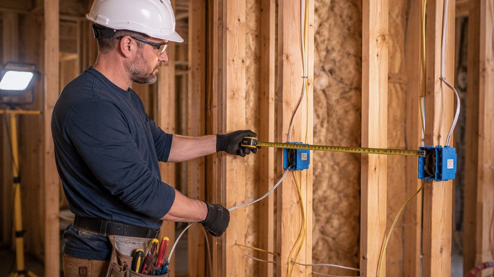
Tape your starting point at the edge of the doorway opening — the door stop side, not the hinge side. From there, measure along the wall surface, following every jog, corner, and recess. The code measures linear wall space, not straight-line diagonal distance, so running a tape across open floor means nothing to an inspector.
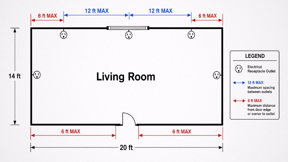
Mark your first outlet location within 6 feet of that doorway edge. Then step out in 12-foot intervals along the wall face, marking each outlet position as you go. Every point along the wall must sit within 6 feet of the nearest outlet — not 6 feet from the doorway, not 6 feet from a corner, from the nearest outlet. The two numbers work together: 6-foot maximum from any doorway, 12-foot maximum spacing between any two outlets. Sketch these marks directly onto the floor plan in pencil before committing box locations to the framing layout. Moving a box three studs over during rough-in is a 10-minute fix; moving it after drywall is an afternoon.
Irregular Rooms: L-Shapes, Alcoves, and Built-Ins
L-shaped rooms trip up newer electricians because the inside corner resets the measurement logic. Treat each leg of the L as its own wall run. Measure around the corner along the wall surface; don’t cut across the open floor. Alcoves wider than 2 feet count as usable wall space and need their own outlet coverage — if the alcove has more than 2 feet of unbroken wall, you can’t skip it.
Fixed cabinetry, built-in shelving, or any permanent obstruction projecting more than 2 inches from the wall breaks the usable wall space for measurement purposes. A kitchen island with a built-in bookcase end panel, for example: measure to the face of the cabinet, stop, restart on the other side. Bay windows are measured at the sill line along the floor plane — the angled glass sections count as wall space for outlet placement.
Worked Example: 20-Foot × 14-Foot Living Room
Take a rectangular living room, 20 feet wide along the long wall and 14 feet on the short walls. One door centered on a short wall, one window on the opposite short wall, no obstructions.
Long wall (20 feet): first outlet within 6 feet of the door edge, roughly at the 5-foot mark. Next outlet at 17 feet. That leaves a gap of 12 feet exactly, which passes. The far end is 3 feet from the second outlet — fine.
Short wall with window (14 feet): outlet within 6 feet of the door, then one more at the 13-foot mark. The window itself doesn’t eliminate the outlet requirement at the sill; you still need coverage within 6 feet below or beside it.
Total outlets: roughly 6 to 8 for a room this size, depending on furniture wall layout and doorway count. For a 15 A circuit using 14 AWG copper, keep the load below 1,440 W continuous. A 20 A circuit with 12 AWG copper gives you roughly 1,920 W continuous headroom — worth the upgrade if the homeowner plans any powered media equipment on that wall.
A 12 AWG copper conductor is required for 20 A branch circuits under NEC 310.12.True
NEC Table 310.12 specifies 12 AWG copper as the minimum conductor size for 20 A circuits. Using 14 AWG on a 20 A breaker is a code violation and a fire risk.
Measurement Mistakes That Fail Inspection
Measuring through the doorway opening — diagonally from one outlet to another across the door — is the most common error. Inspectors measure along the wall, and so should you.
Behind doors is another chronic miss. The wall space behind a swinging door counts if it’s more than 2 feet wide. Don’t assume “nobody puts furniture there” is a valid excuse. The inspector doesn’t care about furniture placement.
Fireplace hearths that project out from the wall face are treated as obstructions. Measure to the face of the hearth projection, not through it.
Digital Tools and BIM Workflows
Most current Revit MEP environments have plugin options — ElumTools, ETAP’s layout modules, or custom Dynamo scripts — that can flag 6-12 compliance gaps automatically during schematic design. The value is catching violations before the electrical drawings go to permit. In practice, BIM doesn’t replace a human doing a final wall-by-wall check on the printed plan, especially in renovations where existing walls are field-verified differently than modeled.
Rough-In Documentation Checklist
Inspectors during rough-in typically verify: outlet box height (typically 12 to 18 inches to center, though this varies by jurisdiction and ADA requirements), device box plumb and flush to stud face within roughly 1/4 inch of anticipated drywall surface, wire secured within 12 inches of each box, and circuit identification marked at the panel. Deviations from standard outlet spacing — say, a location blocked by structural framing — need a written variance request filed before rough-in inspection, not after. Document the obstruction with a photo, note the closest compliant alternative position, and attach it to the inspection card. Inspectors generally accept honest paperwork; they don’t accept surprises.
Cable and Conductor Selection for 6 12 Rule Compliant Branch Circuits
Conductor Gauge: 14 AWG vs. 12 AWG and Why Most Professionals Default to 12
NEC 310.12 permits 14 AWG copper on 15 A branch circuits, and it’s technically legal. But in practice, most experienced electricians and electrical engineers specify 12 AWG throughout the dwelling and be done with it. The reason is straightforward: 12 AWG on a 20 A circuit gives you a meaningful headroom buffer — roughly 25% more current capacity — and it handles voltage drop better on runs that creep past 40 or 50 feet. The incremental material cost is real but modest, usually somewhere in the range of $0.08–$0.15 per linear foot more for the cable, depending on copper spot price at the time of procurement. Against a callback, a breaker nuisance trip from a vacuum cleaner or a window AC unit, or a failed inspection because someone mixed 14 AWG on a 20 A circuit, that cost difference disappears fast.
The professional preference for 12 AWG also reduces job-site error. When you have two gauges running through the same walls, somebody will eventually land 14 AWG on a 20 A breaker. It happens. Standardizing on 12 AWG eliminates that failure mode entirely.
NM-B Cable Construction: What’s Inside the Jacket Matters
Residential branch circuits in the US are almost universally wired with NM-B (Type Non-Metallic Sheathed Cable, colloquially “Romex,” though that’s a brand name from Southwire). The construction is fairly simple: two or three current-carrying conductors, a bare copper grounding conductor, a paper or thin film separator between the conductors, and a PVC outer jacket. The critical rating detail that gets misread on specs: NM-B conductors are rated 90°C in free air but the terminal rating at the device or panel is limited to 60°C. That distinction drives derating decisions, and ignoring it is how you end up with nuisance trips or prematurely degraded insulation at the termination point.
Voltage Drop on Long Branch Circuit Runs
The 6 12 outlet spacing rule can push branch circuit runs to 50 feet or longer in larger rooms or open floor plans, especially when the panel sits on one end of the structure. At those lengths, voltage drop becomes a real calculation, not a formality.
The standard formula: Vd = (2 × K × I × L) / CM
Where K is the resistivity constant for copper (approximately 12.9 for copper in most practical references), I is the load current in amperes, L is the one-way run length in feet, and CM is the cross-sectional area of the conductor in circular mils.
Worked example: 20 A circuit, 50-foot run, 12 AWG copper (6,530 CM).
Vd = (2 × 12.9 × 20 × 50) / 6,530 = 25,800 / 6,530 ≈ 3.95 volts
On a 120 V circuit that’s roughly 3.3% — just over the NEC-recommended 3% branch circuit guideline. Not a code violation in most jurisdictions, but enough that a quality-minded installer or a fussy AHJ will flag it. Upsizing to 10 AWG (10,380 CM) drops that to about 2.5%, comfortably inside the limit.
The NEC 3% voltage drop guideline for branch circuits is a mandatory code requirementFalse
NEC 210.19(A) informational note recommends limiting branch circuit voltage drop to 3%, but it is an informational note, not an enforceable code requirement. Enforcement varies by jurisdiction and AHJ interpretation.
When NM-B Is Not Enough: AC and MC Cable Applications
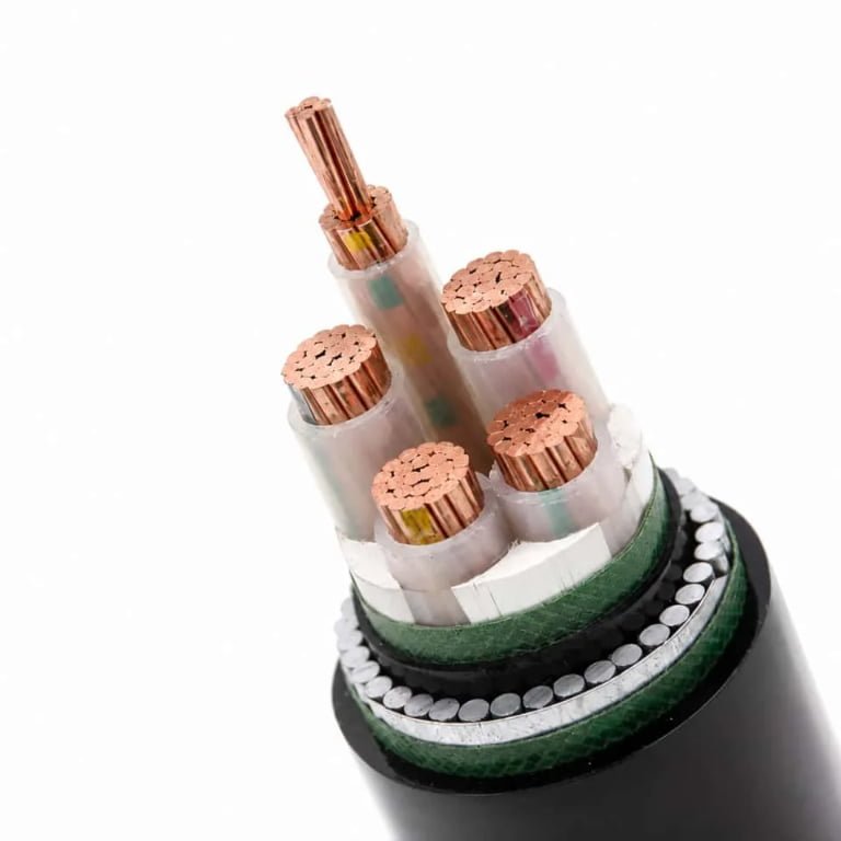
NM-B has limits. NEC 334.10 restricts its use to specific occupancy types — primarily one- and two-family dwellings and certain multifamily applications. In commercial occupancies, exposed locations, above suspended ceilings in some jurisdictions, and anywhere classified as a plenum space, you’re looking at armored cable (AC) or metal-clad cable (MC) as the minimum wiring method, and sometimes conduit. MC cable with a full aluminum or steel interlocked armor jacket handles mechanical abuse and provides an equipment grounding path through the armor itself (though a green insulated ground conductor inside is still required in most configurations). The labor cost for MC is noticeably higher than NM-B — figure 30–60% more per outlet rough-in depending on the crew and layout — but that’s the cost of the occupancy type, not an optional upgrade.
International Projects: IEC-Compliant Building Wire Where NM-B Doesn’t Apply
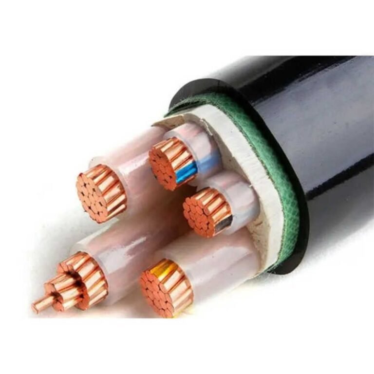
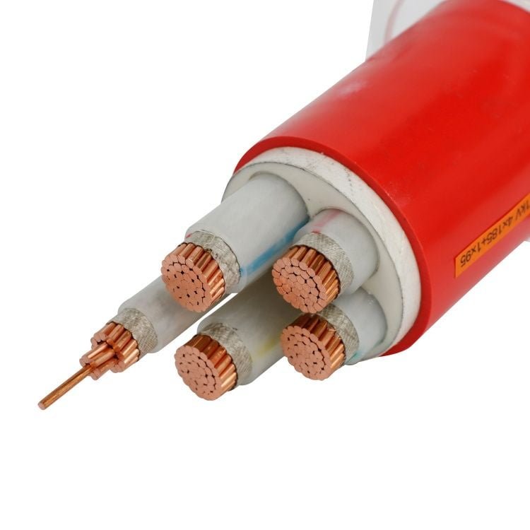
Outside North America, NM-B simply isn’t the specified product. IEC 60227 covers PVC-insulated cables for fixed wiring, and IEC 60502 governs extruded solid dielectric power cables at higher voltage levels. For international building projects requiring compliant branch circuit wiring, Jinda Special Cable Group’s PVC-insulated and XLPE-insulated building wire product lines are engineered to these IEC standards. XLPE insulation in particular offers a higher continuous temperature rating — typically 90°C conductor temperature versus 70°C for standard PVC — which matters when circuits are bundled tightly in conduit or cable tray, or when the installation is in a climate with consistently high ambient temperatures.
Bundling, Ambient Temperature, and NEC Derating
This part gets skipped more often than it should. When you run multiple NM-B cables through a single bored hole, a conduit sleeve, or a bundle tied together above a ceiling, the cables can’t shed heat independently. NEC Table 310.15(B)(1) — the ambient temperature correction table — and the adjustment factors for more than three current-carrying conductors in a raceway both apply. A bundle of four or more cables can require derating the ampacity by 20–50% depending on count and ambient conditions. In an attic above a kitchen in a hot climate, ambient temperatures can run 50°C or higher in summer; that alone triggers meaningful derating. The practical consequence: what was a code-legal 12 AWG / 20 A circuit at rough-in may be thermally marginal by the time insulation is blown in and the attic hits August. Sizing up conductors or keeping bundled runs short isn’t overcaution — it’s recognizing that real buildings are messier than the code diagram.
Alternative Interpretations: Is There a 6 12 Rule for Industrial and Commercial Electrical Systems?
The short answer: in most professional conversations, “6 12 rule in electrical” means NEC Article 210.52 residential receptacle spacing, full stop. But engineers and maintenance electricians encounter the “6” and “12” combination in several other completely unrelated electrical contexts, and mixing them up causes real problems — wrong cable spec, failed inspection, or worse, a technician standing inside an arc flash boundary thinking he’s safely outside it.
Transformer Secondary Voltage Configurations
Some controls engineers use “6-12” informally to describe a control transformer with a 6 V or 12 V secondary winding — common in machine tool panels, HVAC control circuits, and low-voltage lighting systems. This isn’t a codified rule; it’s shop-floor shorthand. A 120 V primary stepped down to 12 V secondary through a Class 2 transformer is standard in hundreds of industrial applications, from indicator lamp circuits to solenoid valve coils. The confusion usually happens when someone reads “6-12 rule” in a forum or spec sheet and assumes it refers to outlet spacing, then undersizes the conductors on a low-voltage branch. Verify context before pulling wire.
Industrial and Commercial Outlet Spacing — Not the Same as Residential
OSHA 29 CFR 1910 Subpart S and NEC Article 511 (commercial garages) impose entirely different logic on receptacle placement. In a commercial garage, the concern isn’t cord length — it’s classified locations, where flammable vapors can accumulate. Receptacles in a Class I, Division 2 environment require explosion-proof fittings and have height restrictions measured from the floor, not lateral spacing measured along walls. NEC Article 513 for aircraft hangars goes further, with floor-level restrictions that have nothing to do with the 6-foot / 12-foot residential formula. Anyone applying residential 6-12 spacing logic to a hangar fit-out is starting from the wrong document entirely.
NFPA 70E Arc Flash and the 6-Foot / 12-Foot Language
This one genuinely trips people up. NFPA 70E uses approach boundary distances — restricted approach, limited approach, arc flash boundary — that can land near 6 or 12 feet depending on system voltage and available fault current. Electricians who’ve recently attended an arc flash training sometimes half-remember “6 feet” or “12 feet” as a safe working distance and conflate it with the outlet spacing rule they learned in apprenticeship. They’re completely separate frameworks. Arc flash boundaries are calculated per incident energy analysis (or estimated from NFPA 70E tables based on system parameters), not prescribed as fixed distances. Treating a calculated arc flash boundary as a loose “rule of thumb” is how people get burned — literally.
NFPA 70E specifies fixed 6-foot and 12-foot arc flash clearance distances for all voltage levelsFalse
NFPA 70E approach boundaries vary with system voltage, available fault current, and equipment type. They are either calculated from incident energy analysis or estimated from standard tables — no single fixed distance applies universally.
Data Centers and Raised-Floor Environments
TIA-942 and BICSI 002 power distribution guidelines for data centers are driven by rack density, PDU reach, and redundant feed paths — not wall-to-wall cord-length logic. Under a raised floor, receptacle placement follows cable management lanes and cooling airflow zones. A typical under-floor PDU might serve a defined row of racks within roughly 1.5 m to 3 m, depending on cable management strategy and redundancy tier. The 6-foot / 12-foot NEC residential formula is irrelevant here.
Marine and Offshore Wiring
IEC 60092 (shipboard electrical installations) and ABYC E-11 (recreational vessels) both use metric spacing and load-zone logic tied to bilge classification, ignition protection, and shore power grounding. A vessel electrician working in meters would find NEC 6-12 foot spacing language meaningless without conversion, and even then the underlying rationale differs.
Confirm context before applying any interpretation. The NEC 210.52 residential rule and these industrial or specialized frameworks share overlapping numbers by coincidence, not by design.
Voltage Drop, Load Calculation, and How They Interact With 6 12 Compliant Circuits
Getting receptacle spacing right per NEC 210.52 is the baseline. What actually determines whether a circuit performs reliably under load — or trips nuisance AFCIs at 2 a.m. — is the voltage drop math and load calculation that most residential electricians treat as an afterthought.
NEC 210.19(A) and the 3%/5% Voltage Drop Guidance
The NEC does not mandate a specific voltage drop limit the way it mandates wire fill or ampacity. The 3% branch circuit / 5% combined feeder-plus-branch figures in the informational note to 210.19(A) are exactly that — informational. But “informational” does not mean ignorable. AHJs in California, New York, and several Canadian provinces have begun citing those figures as enforceable benchmarks, and every major green building program (LEED, ENERGY STAR, Living Building Challenge) treats 3% as a hard ceiling for certification. If you’re doing commercial tenant improvement work and the owner wants LEED Silver, that informational note suddenly has teeth.
NEC 210.19(A) voltage drop figures are recommendations, not mandatory code requirements, but enforcement varies by jurisdiction and programTrue
The NEC Informational Note to 210.19(A) states the recommendation; it is not a mandatory rule under the NEC itself, but local amendments and green building certifications frequently elevate it to a requirement.
In practical terms, a 20 A branch circuit feeding eight or nine receptacles at the far end of a 6-12 rule layout — say, a 50-foot circuit home run in a sprawling single-story — can easily hit 2.8–3.4% voltage drop at full load depending on conductor size and actual load profile. That’s close enough to the 3% figure that you should be running the numbers rather than assuming 12 AWG copper is always sufficient just because it’s rated for 20 A.
Load Calculation: NEC Article 220 and What 180 VA Per Outlet Actually Means
NEC 220.14(I) assigns 180 VA per general-purpose receptacle outlet as the unit load for load calculation purposes. That is not the same as saying each outlet will draw 180 VA — it’s a planning value, and demand factors apply once you tally more than a handful of outlets.
For a 2,000 sq ft dwelling, a realistic receptacle count following 6-12 rule spacing runs 35–45 outlets depending on room layout, peninsula placement, and whether you count dedicated circuits separately. Call it 40. Forty outlets at 180 VA each gives 7,200 VA before demand factors. NEC Table 220.42 lets you apply 100% to the first 3,000 VA and 35% to anything above 3,000 VA for general lighting and receptacle loads in a dwelling. That calculation looks like this: 3,000 VA at 100% plus 4,200 VA at 35% equals roughly 4,470 VA of demand load from receptacles alone. Add your kitchen small appliance circuits (two 20 A circuits, 1,500 VA each) and laundry circuit (1,500 VA), and you’re looking at 8,970–9,500 VA just for those load groups before you add HVAC, water heater, dryer, and lighting load. For a 200 A, 240 V service, that’s easily 40–45% of service capacity allocated before the heavy loads hit.
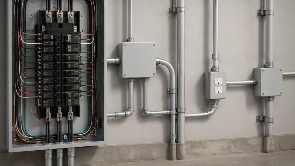
This is why service entrance sizing and branch circuit allocation matter at the design stage, not during inspection.
Conductor Length, Harmonics, and AFCI Nuisance Tripping
Longer branch circuits — which the 6-12 rule permits by default when rooms are large or home runs are long — amplify the interaction between conductor resistance and modern load harmonic content. Switching power supplies, LED drivers, and variable-speed motors all generate third-order and fifth-order harmonics. These harmonic currents don’t register accurately on older clamp meters, which is one reason electricians sometimes can’t reproduce a nuisance trip in the field.
On a 12 AWG circuit running 55–65 feet total (hot plus neutral), resistance climbs to roughly 0.08–0.10 ohms. At moderate harmonic loading, peak currents can exceed the RMS value by a factor of 1.4–1.8. AFCI breakers — especially combination-type units now required throughout most of a dwelling under NEC 2020 — are sensitive to those waveform distortions. The result is intermittent tripping that looks like a defective breaker but is actually the circuit operating outside its design window. Upsizing to 10 AWG on circuits longer than 50 feet in rooms with high concentrations of electronics is not overcautious; it’s just good engineering.
Energy Code Interaction: IECC 2021 and ASHRAE 90.1 Receptacle Control
Commercial occupancies under ASHRAE 90.1-2019 and IECC 2021 require controlled receptacles — typically 50% of non-dedicated outlets in private offices and open workspaces must be switched off during unoccupied periods. That requirement changes how you lay out 6-12 rule branch circuits in commercial applications. Splitting a circuit between controlled and uncontrolled outlets becomes a panel schedule and circuit identification problem during rough-in. If you wire the room by the path of least resistance (literally, the shortest homerun), you’ll likely mix controlled and uncontrolled loads on the same circuit and create a headache during commissioning.
Phantom load from always-on receptacles in office environments runs roughly 0.5–1.2 W per outlet at idle, which sounds trivial until you have 300 outlets in a medium-sized office suite.
Copper vs. Aluminum for Branch Circuit Conductors
Aluminum is rarely used for 15 A or 20 A branch circuits in new residential or light commercial work — not because it’s prohibited, but because termination compatibility at devices and panels remains a persistent installation risk. NEC 110.14 requires that terminals be rated for the conductor material, and most standard receptacles and breakers are rated for copper only or CO/ALR for aluminum.
| Property | Copper (12 AWG) | Aluminum (12 AWG equivalent, ~10 AWG) |
|---|---|---|
| Resistivity | ~1.72 µΩ·cm | ~2.82 µΩ·cm |
| Ampacity (NEC 310.12) | 20 A | ~30 A (10 AWG AL) |
| Termination requirement | Standard Cu-rated | CO/ALR or AL-rated only |
| Material cost (wire only) | Roughly $0.40–0.75/ft depending on copper commodity price | Roughly $0.20–0.40/ft, but larger conduit fill | |
| Practical use in branch circuits | Standard | Rarely used below #6 AWG |
Copper remains the practical default for 6-12 rule branch circuits. At current copper commodity prices — which swing considerably, often $3.50–$4.80/lb at the rod level over a 12-month window — the installed cost difference between 12 AWG and 10 AWG copper on a long circuit is usually $60–$120 per homerun. On a large project, that adds up. But compared to the labor cost of a callback, a re-pull, or an AFCI replacement, it’s cheap insurance.
Installation Best Practices and Common Code Violations Related to the 6 12 Rule
Knowing the rule is one thing. Getting it through inspection without a correction notice is another. Most 6-12 failures on a punch list aren’t from electricians who don’t know the code — they’re from job-site conditions that make the obvious easy to overlook.
Top Five Inspection Failures in the Field
The outlet hidden behind a swinging door panel is probably the single most common citation. NEC 210.52 requires that no point along a wall be more than 6 feet from a receptacle, measured along the wall surface. A door that swings open and parks flat against a wall creates a usable wall section behind it. Inspectors count that section. The outlet on the opposite side of the doorway doesn’t satisfy the requirement for the wall space behind the door. Fix it during rough-in — pulling additional wire after drywall is expensive.
Stairway walls over 10 feet catch people off guard because stairs feel like a transition space rather than a living area. A straight stairwell wall measuring more than 10 feet horizontally still falls under the general wall-space rule in most AHJ interpretations. No outlet, no pass.
Kitchen counter gaps exceeding 2 feet from the edge are a persistent remodel problem. The rule requires a receptacle within 2 feet of the end of every counter section, and another every 4 feet along the counter run. When contractors break a counter layout into segments to work around a corner or a cooktop, they sometimes lose track of each segment as its own measurement zone.
Non-GFCI outlets in garages remain surprisingly common in occupied homes built before the 1978 NEC cycle. Any outlet at or below 6.5 ft in an attached or detached garage needs GFCI protection under current code, full stop. When an older home is partially rewired or an addition is permitted, the AHJ typically requires the entire affected circuit to be brought to current standard.
Bathroom outlets inside the shower zone — meaning within 3 feet of the tub or shower threshold without proper GFCI protection and without being inside the wet zone itself — still appear on inspection reports. The distinction between the GFCI-required zone and the outright prohibited zone trips up both installers and remodelers.
Box Fill: The Violation That Rides Along
NEC 314.16 box fill violations frequently travel with spacing errors. When an electrician adds a receptacle to meet the 6-12 spacing rule in an existing box that already has two conductors, a ground, a clamp, and a device in it, the math often doesn’t work out. Each 12 AWG conductor counts as 2.25 cubic inches. A standard single-gang device box at 18 cubic inches fills up fast. In practice, move to a deeper box or a dual-gang configuration — don’t try to squeeze a code-compliant location into an undersized enclosure.
Retrofit and Remodel Realities
Homes built before roughly 1965 predate broad 6-12 enforcement. Fishing wire through finished walls is genuinely difficult depending on construction type — balloon-frame houses have continuous stud cavities that make top-to-bottom runs easier; platform-frame construction has fire-blocking at each floor level that has to be drilled through and then restored with fire-stop material. Most AHJs require a permit for any new outlet in a finished renovation, and that permit triggers an inspection. Skipping the permit to avoid the hassle almost always costs more when discovered during a future sale inspection.
Tamper-Resistant Receptacles: Still Getting Missed
All 15 A and 20 A 125 V receptacles in new and renovated dwelling units have been required to be tamper-resistant under NEC 406.12 since the 2008 code cycle.True
NEC 406.12 mandates tamper-resistant receptacles in all areas of dwelling units for 15 A and 20 A 125 V receptacles, a requirement that has been in effect since the 2008 edition of the NEC.
The TR mandate is now well into its second decade, yet inspectors still cite non-TR devices regularly — usually because a contractor bought a bulk pack of standard receptacles before job start and didn’t verify the rating. TR-rated devices are identifiable by the letters “TR” molded into the face. Cost difference between TR and standard is minimal at the unit level; failing inspection and returning to site is not.
Documentation and As-Built Requirements
A compliant as-built drawing should show every outlet location with its circuit number, the wire gauge serving that circuit, the breaker rating, and the GFCI or AFCI protection type where applicable. The AHJ wants to trace any outlet back to its overcurrent device without guessing. Building owners — especially commercial tenants or future buyers — need to know what’s behind the walls. An as-built that shows only a rough floor plan with unlabeled outlet symbols satisfies almost no one. Depending on the jurisdiction, panel schedules tied to the drawing are also required at final inspection.
Cable Quality and Factory-Level Testing
Field failures related to voltage drop or thermal behavior on branch circuits aren’t always a design error — sometimes they trace back to conductor resistance outside tolerance. Jinda Special Cable Group’s ISO 9001-certified production process includes 100% conductor resistance testing on finished wire, which means a spool that leaves the factory has a verified conductor cross-section, not one that drifted during extrusion. For contractors running 12 AWG on 20 A circuits across the 6-12 rule outlet layout, that consistency matters: a conductor that runs slightly undersized across a 40-foot branch circuit run will show elevated resistance, and you won’t find out until the circuit is loaded and the voltage drop calculation becomes a field problem rather than a design one.
Frequently Asked Questions About the 6 12 Rule in Electrical
Does the 6-12 rule apply to every room in a house?
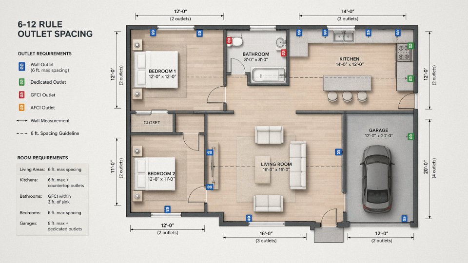
No — and this is probably the most common misconception that trips up electricians on residential inspections. The 6-12 rule as defined in NEC Article 210.52(A) applies specifically to habitable rooms and certain other spaces, but each room type has its own sub-rule. Hallways 10 feet or longer require at least one receptacle, but no continuous wall-spacing math applies the way it does in a living room. Bathrooms fall under 210.52(D): you need at least one outlet within 3 feet of the outside edge of the basin, full stop — the 12-foot wall-spacing logic doesn’t govern the rest of the room. Kitchens are a world of their own under 210.52(C), where countertop surface spacing (no point more than 24 inches from an outlet measured along the wall) replaces the standard rule. Closets, laundry rooms, and unfinished basements each have their own treatment. Applying the 6-12 rule universally across an entire house plan is a fast path to a failed rough-in inspection.
Can a single 15 A circuit supply all the receptacles in a living room under the 6-12 rule?
Technically, NEC doesn’t prohibit it if your load calculation comes in under the circuit’s ampacity. In practice, though, almost no competent residential designer does this anymore. A 15 A circuit on 14 AWG gives you roughly 1,440 W of usable continuous load — which disappears fast once someone plugs in a space heater, a gaming setup, or a window AC unit. Most residential designs now run 20 A circuits with 12 AWG copper on living spaces precisely because future load growth is unpredictable and the cost delta between 14 AWG and 12 AWG on a typical room circuit is small. Voltage drop also gets worse on 15 A/14 AWG runs in larger rooms, especially if the panel is on the opposite side of the house. The 6-12 rule doesn’t say anything about circuit ampacity — that’s a separate calculation — but the two interact directly on long walls.
NEC 210.52 requires outlets no more than 12 feet apart along any wall in general living areas of a dwelling unitTrue
NEC Article 210.52(A) specifies that receptacles must be placed so no point along the floor line is more than 6 feet from an outlet, which geometrically produces the 12-foot maximum spacing between outlets along a continuous wall.
What happens if existing outlets don’t meet the 6-12 rule?
Older homes — anything built before the relevant NEC cycle was adopted locally — often have outlet spacing that would fail today’s code. NEC 80.19 covers existing installations: non-compliant outlets that haven’t been disturbed are generally grandfathered. The trigger for full compliance is opening the wall. Any remodel that exposes the framing cavity in an altered area requires bringing that section up to current code. Inspectors interpret “altered area” differently by jurisdiction, so if you’re managing a partial renovation, clarify the scope with your AHJ (Authority Having Jurisdiction) before rough-in. Some inspectors will require compliance on the entire affected wall; others stop at the work zone. Don’t assume.
Is the 6-12 rule identical in Canada and Mexico?
Close but not identical. Canada’s CEC Part I Rule 26-700 uses a similar spacing philosophy — no point on a wall more than 1.5 m from a receptacle, which works out to just under 5 feet, tighter than the NEC’s 6-foot figure. The 12-foot maximum between outlets is conceptually preserved, but the measurement methodology and room exemptions differ in detail. Mexico follows NOM-001-SEDE, which has its own outlet spacing provisions shaped partly by IEC practice; the specific distances and room classifications don’t map cleanly onto NEC language. If you’re managing a cross-border development project or specifying cable for installations in all three countries, verify the local standard before locking in your design — assume nothing transfers automatically.
Does the 6-12 rule govern outdoor receptacles?
No, exterior walls are handled separately under NEC 210.52(E). For dwelling units, you need at least one accessible receptacle at the front and one at the rear at grade level, plus one in any attached garage. The 6-12 wall-spacing logic that applies inside habitable rooms doesn’t extend to the exterior perimeter. GFCI protection is mandatory on all outdoor receptacles regardless of location, per 210.8(A). Weatherproof cover requirements under 406.9 add another layer that has nothing to do with spacing.
What cable type works best for long receptacle runs?
For branch circuit runs exceeding roughly 50 feet on a 20 A circuit, staying with 12 AWG copper can push you past the 3% voltage drop threshold NEC recommends — not a code violation in most jurisdictions, but a performance problem that shows up as dimming lights, tripping GFCI devices, and warm conductors under load. Upsizing to 10 AWG copper on those longer homerun segments keeps drop in acceptable range and gives you headroom if the load grows. For large residential or light commercial projects requiring verified conductor cross-sections and IEC-compliant construction, Jinda’s copper conductor building wire is available in bulk quantities — useful when a project involves dozens of long runs and consistent conductor quality matters for both compliance and lifecycle cost.