Specifying cable for a mixed electrical and data infrastructure project is messier than it looks on paper. Facilities teams, contractors, and procurement managers regularly wrestle with whether Cat6 falls under electrical low-voltage regulations, communications codes, or both — and getting that classification wrong has real consequences: wrong conduit fill calculations, failed inspections, re-pulls that cost thousands of dollars and weeks of schedule, or worse, an insurance dispute after a fire in a cable tray where data and power cables were bundled without following the correct separation rules.
Cat6 is considered low voltage. Signal voltages during normal data transmission run well under 5V DC, and even Power over Ethernet under IEEE 802.3bt tops out at 57V DC — far below the 1000V AC / 1500V DC threshold that IEC 60364-4-41 uses to define low voltage. In the United States, NEC Article 800 classifies Cat6 as a communications cable, which carries its own installation requirements distinct from general electrical wiring but still within the low-voltage domain.
What makes this question stickier in practice is that “low voltage” means different things depending on who’s asking. An electrical inspector reading NEC thinks in terms of wiring methods and separation requirements. A network engineer thinks about signal integrity and PoE power budgets. A procurement manager sourcing cable for a hospital or industrial facility needs to satisfy both camps simultaneously — and the standards don’t always use the same vocabulary. Understanding where Cat6 actually sits across those frameworks changes how you specify conduit, plan cable trays, and write purchase orders.
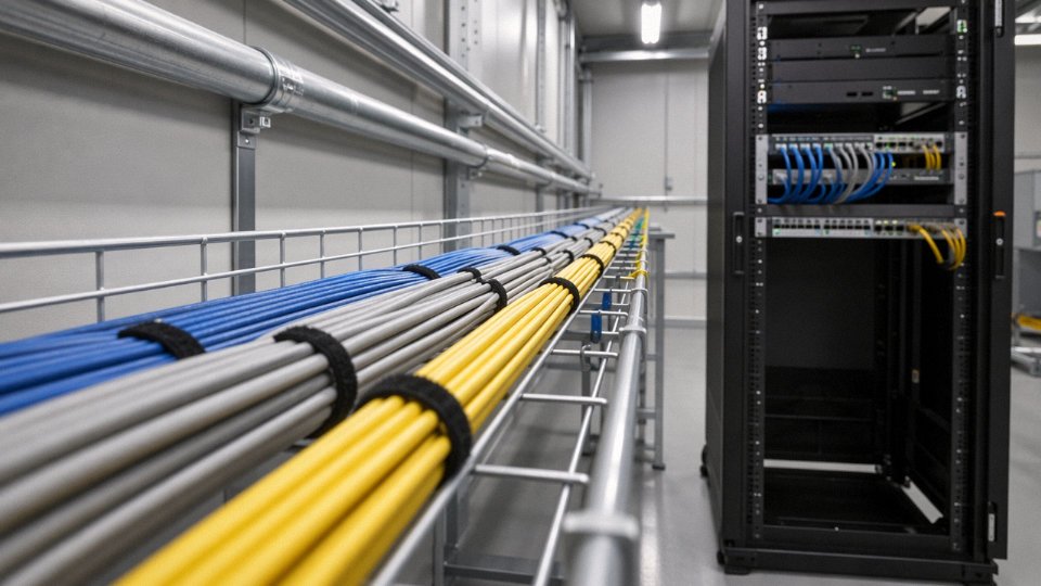
Voltage Levels Inside a Cat6 Cable: Data Signals, PoE, and the IEEE 802.3 Framework
Most engineers who ask whether Cat6 is “low voltage” are really asking two different questions at once — and conflating them leads to real installation and procurement mistakes. The first question is about the signal voltage during pure data transmission. The second is about what happens when you add Power over Ethernet. They have different answers, but both land well within the low-voltage band.
Baseline Ethernet Signaling: Genuinely Tiny Voltages
During standard 1000BASE-T operation, the differential signal on a Cat6 pair sits at roughly 1V peak-to-peak. That’s not a rounding simplification — it’s genuinely that low. The actual power dissipated in the cable at this level is in the milliwatt range, essentially negligible from any electrical safety or thermal standpoint. 10GBASE-T runs at comparable levels, though the signal encoding is more complex.
In practice, this means a Cat6 cable carrying only data is closer electrically to a sensor wire than to anything you’d find in a panel. No special PPE, no arc-flash concern, no derating for thermal load from the signal itself.
Where Voltages Actually Rise: The PoE Generations
Power over Ethernet changes the picture — not dramatically, but enough that engineers need accurate numbers for cable selection and budget calculations.
The three active IEEE 802.3 PoE standards carry these parameters:
| Standard | Max Power (PSE output) | Nominal Voltage | Pairs Used |
|---|---|---|---|
| 802.3af (PoE) | 15.4 W | Up to 48V DC | 2 pairs |
| 802.3at (PoE+) | 30 W | Up to 57V DC | 2 pairs |
| 802.3bt (PoE++) | 90 W | Up to 57V DC | 4 pairs |
Those are the open-circuit or source-side voltages — what the Power Sourcing Equipment (PSE) puts on the cable before any resistive drop. By the time you measure at the Powered Device (PD) end of a 100-meter Cat6 run, you’ll see a meaningful voltage drop. A 24 AWG Cat6 conductor has a DC resistance of roughly 9.4 Ω per 100 meters; with four pairs carrying current under 802.3bt, the total drop across a full-length run can eat 5–12V depending on load, conductor gauge, and temperature. This matters for PoE budget calculations — if your PD needs a minimum input voltage of 42V to operate reliably, running maximum cable length at maximum load is a real engineering constraint, not a theoretical one.
Under IEEE 802.3bt, Cat6 can carry up to 90W of power at voltages up to 57V DC.True
IEEE 802.3bt (Type 3/Type 4 PoE) specifies a maximum PSE output of 90W using all four pairs, with a maximum open-circuit voltage of 57V DC. This is documented in the IEEE 802.3bt-2018 standard.
Why 57V DC Does Not Make Cat6 a Medium-Voltage Cable
This is the misconception worth addressing directly. Some installers — and occasionally a building inspector who hasn’t seen a PoE deployment before — assume that adding power to a data cable bumps it into a different regulatory category. It doesn’t.
IEC 60950-1 and its successor IEC 62368-1 both classify circuits operating below 60V DC as Safety Extra-Low Voltage (SELV). At 57V DC, PoE sits just under that threshold. The shock hazard at this voltage level, while not zero, is categorically different from mains voltage — the human body resistance and let-go current thresholds make 57V DC a manageable risk under normal conditions, which is exactly why the SELV classification exists.
To put the numbers in context:
| Circuit Type | Typical Voltage | Classification |
|---|---|---|
| Cat6 data signal | ~1V DC (differential) | Signal only |
| Cat6 with PoE (802.3af) | Up to 48V DC | SELV |
| Cat6 with PoE++ (802.3bt) | Up to 57V DC | SELV |
| NEC Class 2 wiring | ≤30V | Limited energy |
| Residential mains (North America) | 120V AC | Low voltage (utility) |
| Residential mains (Europe/China) | 230V AC | Low voltage (utility) |
The “low voltage” label in building codes covers an enormous range. Mains power at 230V AC is still technically “low voltage” under IEC 60364. Cat6, even fully loaded with 802.3bt PoE, operates at a fraction of that — roughly one-quarter of European mains voltage. The cable’s insulation, listed to UL 444 or equivalent, is rated well above what it will ever see in service.
One operational note worth keeping in mind: while the voltage classification doesn’t change, the thermal load under 802.3bt does. Bundled Cat6 cables carrying 4-pair PoE in a tightly packed conduit or cable tray can experience temperature rise that degrades signal performance — not a safety issue, but a real performance issue that affects cable selection and routing decisions.
Regulatory Classification: How NEC, IEC, and EN Standards Formally Categorize Cat6
Understanding what the codes actually say — not just the informal label — matters the moment you’re pulling permits, writing a specification, or disputing an installation method with a contractor. The short answer is that Cat6 sits comfortably within the low-voltage tier under every major regulatory framework, but the specific code articles involved have real installation consequences that are easy to get wrong.
NEC Article 800: Communications Circuits and the Separation Mandate
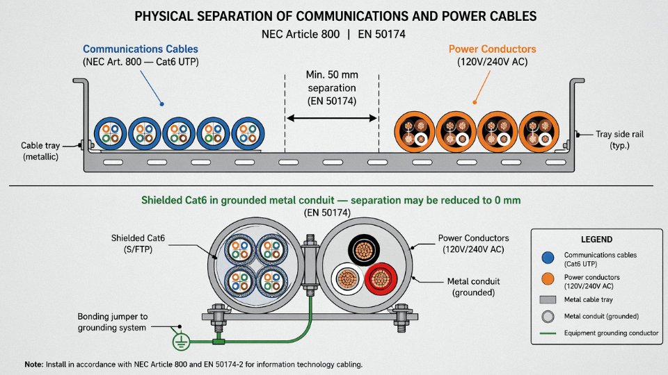
In the United States, Cat6 falls under NEC Article 800, which governs communications wiring including telephone, data, and network cable. Article 800 is not the same jurisdiction as Chapter 3 wiring methods for power circuits, and that distinction matters in practice. Under Articles 800.133 and the cross-referenced requirements in Article 300, Cat6 conductors must be physically separated from power conductors — not just in separate conduits where convenient, but as a code requirement tied to insulation voltage ratings and induced-noise risk.
The co-bundling restriction is where installers get into trouble. Routing Cat6 alongside 120V or 240V AC mains in the same conduit or cable tray section is a violation unless specific exceptions apply (a listed combined-use cable, or an approved barrier). In open plenum runs, the separation requirement persists; you cannot simply tie a data bundle to a power bundle with cable ties and call it done. Article 725, which covers Class 1, Class 2, and Class 3 remote-control and signaling circuits, overlaps with PoE-enabled Cat6 runs. A PoE circuit operating at voltages not exceeding 150V and power not exceeding 100 VA generally qualifies as a Class 2 circuit — and that classification affects conduit fill calculations, permitted wiring methods, and whether the circuit needs overcurrent protection at the source. It does not change the physical cable design at all; the same Cat6 cable is used regardless. That distinction trips up procurement specs fairly often.
IEC 60364-4-41: SELV, PELV, and the ELV Threshold
IEC 60364-4-41 defines Safety Extra-Low Voltage (SELV) and Protective Extra-Low Voltage (PELV) systems, with the ELV boundary set at 50V AC or 120V DC ripple-free. Cat6 data circuits, which carry signal voltages well below 5V in normal operation, fall unambiguously into SELV territory. PoE circuits under IEEE 802.3bt — even at the upper end around 57V DC — sit just above the ELV threshold in strict IEC terms, which means a 802.3bt Type 4 PoE installation technically requires attention to IEC’s touch-voltage provisions. This is rarely a problem in practice because the PSE (power sourcing equipment) controls voltage application until a valid PD signature is detected, but it is worth documenting in your project’s electrical risk assessment.
All PoE voltages on Cat6 cable fall within IEC 60364's ELV classification of below 50V AC / 120V DC.False
IEEE 802.3bt (Type 3 and Type 4) PoE can reach up to 57V DC, which technically exceeds IEC 60364-4-41's ELV threshold of 50V AC / 120V DC ripple-free. Most 802.3af and 802.3at deployments do fall within ELV, but the highest-power PoE tier does not.
EN 50174: Physical Segregation Distances in Practice
EN 50174 (Information Technology — Cabling Installation) is the European standard that gets most specific about physical separation between Cat6 and power cables. The headline figure is a 50 mm minimum separation from unshielded mains wiring — but that number depends on several variables: the power cable’s voltage band, whether the data cable is shielded (STP/SFTP), and whether either cable runs inside metallic conduit. Shielded Cat6 in a grounded metallic conduit can reduce the required separation substantially, sometimes to zero separation with conduit walls providing the barrier. Unshielded UTP Cat6 parallel to 230V mains for a long run with no conduit? That 50 mm minimum is non-negotiable, and in noisy industrial environments many experienced installers push it to 100–150 mm as a working habit.
TIA-568.2-D and ISO/IEC 11801: Structured Cabling Prerequisites
ANSI/TIA-568.2-D, the dominant North American structured cabling standard, does not itself assign a voltage classification to Cat6. It defers entirely to NEC and applicable local electrical codes for that determination. What TIA-568.2-D does establish is the performance requirements — channel and permanent link test parameters — that Cat6 must meet. Compliance with TIA-568.2-D is typically a prerequisite for manufacturer structured cabling warranties, so specifying “Cat6 to TIA-568.2-D” in a procurement document means you’re defining electrical performance, not voltage class.
ISO/IEC 11801 Edition 3 handles the international equivalent, covering Cat6 under Class E and Cat6A under Class EA. It aligns directly with IEC 60364’s voltage classification scheme, so a project documented to ISO/IEC 11801 and IEC 60364 has a coherent regulatory stack without contradiction. That alignment matters when you’re supplying cable into a project spanning multiple jurisdictions — a plant in Germany that also follows local NEC-equivalent codes will reference both frameworks, and knowing they are consistent saves time during design approval.
Physical Construction of Cat6 Cable and How It Relates to Voltage Rating
Cat6 cable looks deceptively simple from the outside. Pull back the jacket and you find a tightly engineered assembly where every material choice — conductor gauge, insulation compound, jacket formulation — has a direct bearing on how the cable handles voltage, heat, and high-frequency signal propagation simultaneously.
Conductor: 23 AWG or 24 AWG Solid or Stranded Bare Copper
Most Cat6 horizontal runs use 23 AWG solid bare copper, though 24 AWG appears in patch cords and some flexible installation scenarios. The difference matters more than people expect. Solid 23 AWG copper typically measures around 9.38 Ω per 100 m (give or take, depending on drawing tolerances and copper purity grade — OFC versus standard ETP copper will shift this slightly). Move to 24 AWG solid and that resistance climbs to roughly 9.38 × 1.26, putting you closer to 11.8–12 Ω per 100 m.
Why does this matter for a “low voltage” cable? PoE. Under IEEE 802.3bt Type 4, a powered device can draw up to 71 W, and the PSE transmits at up to 57 V DC across the pairs. At 90 meters of 24 AWG, resistive voltage drop across both conductors in a pair can eat 5–8 V depending on load current — enough to push a marginal PoE device into reset cycles or intermittent brownouts. 23 AWG solid reduces that drop by roughly 15–20%, which in a real building with long runs to ceiling-mounted access points is the difference between a stable deployment and a facilities team chasing ghost faults for two weeks.
Insulation: HDPE and FEP Dielectrics Rated Well Above Operating Voltage
Each of the eight conductors is individually insulated, typically in HDPE (high-density polyethylene) or FEP (fluorinated ethylene propylene) depending on the cable’s temperature and flame performance requirements. Both materials have dielectric breakdown voltages in the range of 20–30 kV/mm — orders of magnitude above anything Cat6 will ever see in service. The voltage handling capacity is, frankly, not the engineering challenge here. The challenge is maintaining stable dielectric constant (around 2.1–2.3 for HDPE, slightly higher for FEP) and consistent insulation geometry at 250 MHz, because signal integrity at Category 6 frequencies is far more sensitive to impedance variation than to voltage stress.
This is worth stating clearly for procurement teams: you are not buying thick insulation for voltage protection. You are buying tightly controlled insulation thickness and concentricity to hit the 100 Ω ±15 Ω characteristic impedance window required by TIA-568-C.2 and ISO/IEC 11801.
Cat6 cable insulation has dielectric breakdown ratings well above 1000VTrue
HDPE and FEP insulation materials used on individual Cat6 conductors typically withstand 20–30 kV/mm, placing their practical breakdown voltage far above the IEC low voltage threshold of 1000V AC or 1500V DC.
Jacket Compounds and Fire Performance Classifications
The overall jacket is where fire performance classifications come into play, and this is where procurement decisions get consequential in a hurry. NEC Article 800 recognizes three primary ratings for Cat6:
| Jacket Rating | Application | NEC Classification | Key Property |
|---|---|---|---|
| CMP | Air-handling plenum spaces | Plenum | Low flame spread, low smoke |
| CMR | Vertical riser between floors | Riser | Flame containment in vertical runs |
| CMX | Residential / general purpose | General | Basic flame resistance only |
In European projects, the Construction Products Regulation (CPR) classification applies instead. Eca is the minimum acceptable for most commercial installations; Dca and Cca ratings indicate progressively better flame spread and smoke emission performance, with Cca typically required in public buildings and transport infrastructure in many EU member states.
Outdoor-rated Cat6 uses a PE (polyethylene) jacket — UV-stabilized, moisture-resistant, and generally black for UV protection. Direct-burial variants add a flooding compound or additional PE sheath. LSZH (low-smoke zero-halogen) jackets are worth specifying in confined public spaces not because the voltage ratings change, but because halogen combustion products from PVC are corrosive to electronics and genuinely dangerous to occupants in a fire scenario.
Shielded Variants: F/UTP, U/FTP, and S/FTP
Shielding adds complexity that unshielded Cat6 avoids. In F/UTP construction, an overall aluminum foil wraps all four pairs; U/FTP shields each pair individually; S/FTP combines a braided overall screen with individually foiled pairs. The shielding itself carries no voltage in normal operation, but it must be bonded to ground at least at one end — and in practice, proper bonding at both ends per EN 50174-2 and IEC 60364-5-54 is required to avoid ground loops in sensitive environments.
The operational payoff is real: shielded Cat6 can often be routed with reduced separation distances from power cables — sometimes as low as 50 mm versus the 200 mm typically required for unshielded cable near unshielded power wiring — which matters enormously in congested cable trays. That said, a poorly terminated shield is worse than no shield. If the drain wire is left floating at one end by an installer who didn’t understand the grounding requirement, you’ll inject more noise than an unshielded cable would have.
Spline and Cross-Filler: Signal Integrity, Not Voltage Isolation
Most Cat6 cables include a plastic cross-filler or spline running longitudinally through the cable core, separating the four pairs into quadrants. This piece does nothing for voltage rating. It exists purely to maintain pair geometry, control pair-to-pair spacing, and reduce alien crosstalk (AXT) — the failure mode that causes Cat6 to underperform relative to specification in dense bundle installations. Remove the spline and the cable may still pass basic continuity testing while failing NEXT and PSANEXT limits. For long horizontal runs where multiple cables occupy the same conduit, the spline is what keeps the Category 6 performance certification valid.
Manufacturing Controls That Connect Construction to Performance
At Jinda, Cat6 production runs through conductor drawing and annealing lines that target OFC-grade copper with controlled oxygen content to minimize resistivity variation batch to batch. Insulation extrusion is monitored for wall thickness tolerance — typically ±0.01–0.02 mm depending on conductor gauge — because concentricity directly affects characteristic impedance consistency along the full cable length. Every reel passes a 100% spark test, applying a test voltage (typically 1.5–2 kV AC, per IEC 60502 principles adapted for data cable) across the insulation to catch pinhole voids before the cable ships. Routine electrical verification covers DC resistance, insulation resistance, and attenuation per IEC 60332 (flame propagation) and IEC 60754 (halogen content for LSZH grades). These aren’t impressive-sounding quality steps — they’re the baseline that separates cable you can trust on a 10-year infrastructure deployment from material that passes the box label and fails the certification audit.
Installation Rules That Apply Because Cat6 Is Low Voltage: Separation, Conduit, and Grounding
Low-voltage classification does not mean low-consequence installation. Get the routing wrong and you end up chasing intermittent link errors, failing a fire inspection, or — in a PoE deployment — dealing with unexpected voltage drops that kill IP cameras mid-winter when the cable run is longer than the design assumed.
Separation from Mains Power Cabling
NEC 800.133 requires Cat6 to maintain separation from electrical conductors of light, power, and Class 1 circuits unless specific conditions are met. EN 50174-2 Table B.1 puts a practical floor on this: a minimum 50 mm (roughly 2 inches) between unshielded Cat6 and unshielded AC power cables running in parallel. That 50 mm figure assumes standard 230/120V mains; for higher-current feeders or variable-frequency drives, some plant-floor standards push that gap to 200 mm or more, and honestly that’s worth specifying explicitly in your design documents rather than leaving it to the installer’s judgment.
The exception — and it’s a useful one — is shared metallic conduit with a grounded metallic divider. In that configuration, the separation requirement drops to zero because the divider provides the shielding. This is common in commercial fit-outs where conduit space is tight. Just confirm the divider is actually bonded; a floating divider helps almost nothing.
Conduit Fill and Trade Size Selection
NEC Chapter 9, Table 1 limits conduit fill to 40% of the interior cross-sectional area for three or more conductors. Cat6 cables are roughly 7–8.5 mm OD depending on the construction (shielded cables sit at the higher end), which puts their cross-section at approximately 38–57 mm² per cable. A 1-inch EMT conduit has a usable fill area around 460 mm² at 40%, so you can fit roughly 8 standard UTP Cat6 cables — though in practice I’d spec for 6 and leave the rest as capacity for adds and moves. Procurement documents should call out not just the conduit trade size but the fill percentage assumption; otherwise you’ll get conduit that’s technically compliant on paper and physically impossible to pull through on site.
Grounding and Bonding for Shielded Cat6
Shielded Cat6 (F/UTP or S/FTP) must have its metallic sheath bonded to ground per NEC 800.100.True
NEC 800.100 requires bonding of metallic cable sheaths, raceways, and protectors for communications cables. Failure to bond creates a floating shield that can actually worsen noise pickup rather than reduce it.
Single-point grounding — bonding the shield at only one end, typically the patch panel — is the standard approach for horizontal runs and eliminates ground loops. Multi-point grounding is used in some industrial and data center trunk applications but introduces the risk of circulating currents if the ground reference differs across the building, which shows up as noise on the pair. In plants with multiple electrical distribution panels feeding different floors, ground potential differences of 1–3V are not unusual. That’s enough to cause problems on shielded cable bonded at both ends.
Plenum, Riser, and Fire Rating
The low-voltage classification does not exempt Cat6 from fire-rating requirements. This trips people up regularly. CMP-rated (plenum) cable is mandatory in air-handling spaces because the combustion byproducts from the jacket — not the voltage — are the hazard. PVC jackets in a plenum will produce toxic smoke that spreads through the entire air system. Use CMP where required, CMR in vertical risers, and don’t substitute based on voltage logic alone.
Outdoor and Direct-Burial Routing
Direct-burial Cat6 requires a PE outer jacket rated for UV exposure and ground contact. Burial depth is typically 150–300 mm depending on jurisdiction and whether the cable runs under a trafficked surface. Gel-filled variants resist moisture ingress in conduit runs with pooling risk; dry-core cables in a well-drained conduit are easier to terminate and re-pull. Specify which you need in the procurement document — “outdoor Cat6” is not a precise enough description.
Data Center Bend Radius and Bundle Management
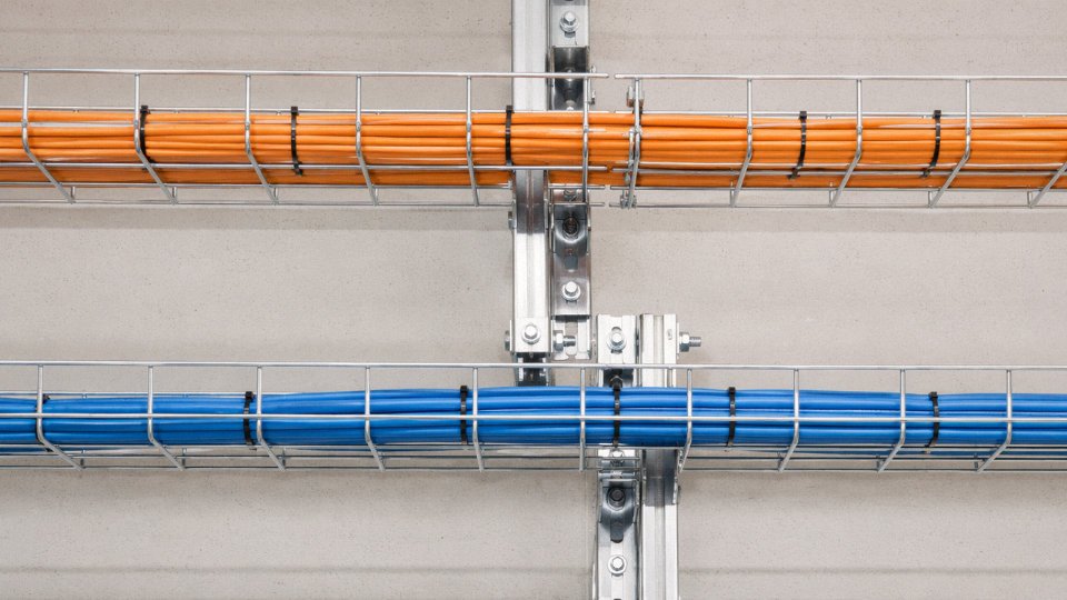
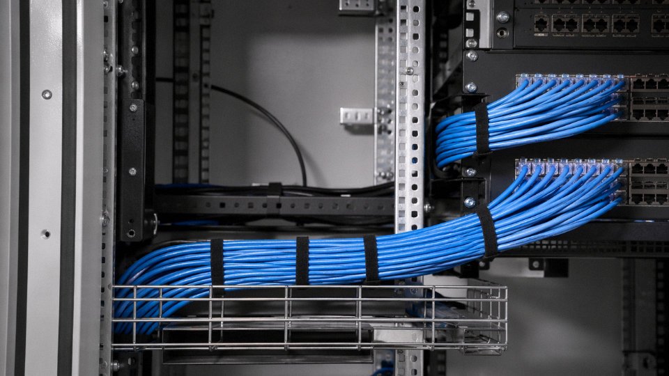
Minimum bend radius is 4× cable OD for UTP Cat6, 8× for shielded variants. Violating this on a patch cable jammed into a dense 1U switch area compresses the twisted pairs and raises insertion loss measurably at 250 MHz — even though the voltage involved is millivolts. Cable management trays should not be loaded beyond roughly 50–60% of their stated capacity; an overloaded tray deforms the cables at the bottom of the bundle over time. Velcro ties rather than cable ties, and leave enough slack at the patch panel for a re-termination without pulling the whole run.
Cat6 Versus Other Cabling Types: Comparing Voltage Ratings, Performance, and Application Fit
Choosing the right cable category isn’t purely a technical exercise — it affects installation labor, conduit fill calculations, future upgrade paths, and whether your PoE budget actually works in the field. Here’s how Cat6 stacks up against the cables it most often gets compared to or confused with.
Ethernet Category Cable Comparison
All copper twisted-pair Ethernet categories — Cat5e through Cat7 — sit in the same low-voltage communications classification under NEC Article 800 and IEC 60364. The differences are in signal performance and, practically speaking, how much heat they shed under high-wattage PoE.
| Cable Type | Bandwidth | Max PoE Support | Conductor AWG | NEC/IEC Class |
|---|---|---|---|---|
| Cat5e | 100 MHz | IEEE 802.3at (30 W) — marginal at 4-pair | 24 AWG typical | Article 800 / Low Voltage Comms |
| Cat6 | 250 MHz | IEEE 802.3bt (up to 90 W, 4-pair) | 23–24 AWG | Article 800 / Low Voltage Comms |
| Cat6A | 500 MHz | IEEE 802.3bt (up to 90 W, full spec) | 23 AWG typical | Article 800 / Low Voltage Comms |
| Cat7 | 600 MHz | IEEE 802.3bt capable | 22–23 AWG | Article 800 / Low Voltage Comms (GG45/TERA connectors complicate this) |
Cat6A is the right call for PoE-heavy deployments — its heavier conductor and tighter thermal spec mean bundle temperature rise stays manageable. Cat5e under 60 W+ PoE in a 24-cable bundle gets warm enough to degrade signal margins, especially in a sealed conduit on a summer roof run. Cat6 hits the practical middle ground for most commercial work.
Cat6 Versus Class 2 Control Cable
Both are low voltage. They are not interchangeable, and this trips up procurement teams more often than you’d expect. Cat6 is engineered for balanced differential signaling — tight pair twist rates, controlled impedance around 100 ohms, and crosstalk suppression up to 250 MHz. Class 2 wiring (thermostat wire, security sensor cable, access control runs) carries slow-changing DC or low-frequency AC control signals where none of that matters. Substituting Cat6 for 18/4 thermostat wire works electrically but wastes money. Running HVAC sensor signals over Cat6 pairs is fine if you have spare conductors, but don’t do it the other way — putting BACnet/IP over Class 2 stranded thermostat wire will give you intermittent link drops and an afternoon you won’t enjoy.
Cat6 Versus Fiber Optic Cable
Fiber carries no electrical voltage at all, which places it entirely outside low-voltage electrical classification frameworks. That’s not a loophole — it’s a genuine design advantage in EMI-dense environments like generator rooms, variable-frequency drive enclosures, or cable trays running parallel to medium-voltage feeders.
Fiber optic cable is immune to electromagnetic interference because it transmits data as light pulses rather than electrical signals.True
Fiber optic cables use glass or plastic cores to carry modulated light, meaning there is no conductive path for EMI to couple into the signal — a fundamental physical property, not a design feature specific to any product.
Choose fiber when runs exceed roughly 90–100 meters, when EMI is a real concern rather than a theoretical one, or when you need bandwidth headroom beyond 10 Gbps. Choose Cat6 when runs are short, PoE is required (fiber cannot deliver power without a separate copper pair or a midspan injector), and first cost matters.
Cat6 Versus Coaxial Cable (RG6, RG59)
Coaxial cable handles RF and CATV distribution — 75-ohm impedance, entirely different signal regime. NEC Article 820 governs coax; Article 800 governs Cat6. Both are low voltage in the broad sense, but they are separately classified, separately installed, and the separation requirements between them and line-voltage wiring differ slightly by jurisdiction. Don’t mix them in the same conduit unless local code specifically permits it.
Application Fit at a Glance
| Application | Recommended Cable | Reason |
|---|---|---|
| IP cameras (indoor) | Cat6 UTP | PoE, short runs, cost-effective |
| IP cameras (outdoor/industrial) | Cat6 F/UTP or armored | Shielding, mechanical protection |
| VoIP phones | Cat6 UTP | PoE 802.3af/at, standard runs |
| Wireless access points (10G uplink) | Cat6A S/FTP | 500 MHz bandwidth, reduced alien crosstalk |
| BACnet/IP building automation | Cat6 UTP or F/UTP | Ethernet-native protocol, standard structured cabling |
| Industrial control panel Ethernet | Cat6 industrial-grade, LSZH or PUR jacket | Temperature rating, chemical resistance, flame class |
| CATV/RF distribution | RG6 coaxial | Article 820 system, 75-ohm impedance match |
| Runs over 100 m, high EMI | Fiber optic (OS2 or OM4) | No voltage coupling, distance-immune |
In practice, most commercial and light industrial projects end up specifying Cat6 as the baseline with Cat6A in riser and high-density PoE zones — and that split covers the majority of real-world cases without over-engineering the budget. For outdoor industrial sites, armored Cat6 in LSZH or PVC jacket handles the physical abuse; for anything near variable-frequency drives or heavy switchgear, shielded F/UTP or S/FTP construction is worth the modest price premium. The cable variants across UTP, F/UTP, and S/FTP in both Cat6 and Cat6A — with LSZH, PVC, or armored jacket options — exist precisely because no single construction suits every low-voltage installation environment.
PoE on Cat6: Thermal Management, Cable Selection, and the 802.3bt High-Power Challenge
High-power PoE is where the “it’s just low voltage” assumption starts costing people money. The voltage stays well within safe limits — 57V DC under IEEE 802.3bt Type 4 — but the thermal problem is real, and it catches facilities teams off guard more often than it should.
Why I²R Heating Is the Design Problem, Not the Voltage
Under 802.3bt Type 3 (up to 60W) and Type 4 (up to 90W), current flows on all four pairs simultaneously. At up to roughly 600mA per pair for Type 4, you’re pushing meaningful I²R losses through a conductor that’s typically 23 or 24 AWG and bundled inside a tray with dozens of identical cables doing the same thing. The cable jacket traps heat. Neighboring cables add more. Ambient temperature inside a congested cable tray can climb 10–20°C above room temperature in a warm plant, depending on ventilation, bundle density, and seasonal load.
That temperature rise matters because elevated conductor temperature increases DC resistance, which increases heat generation further — a compounding effect. In the worst cases, sustained over-temperature degrades the polyethylene insulation, shifts impedance, and causes intermittent link drops that are genuinely difficult to trace. Installers often blame the switch or the endpoint device first.
IEEE 802.3bt Annex N: The Derating Guidance Most Installers Skip
The standard addresses this directly. Annex N of IEEE 802.3bt provides guidance on bundle size limits and ambient temperature adjustments. The core recommendation: bundles of 24 or more Cat6 cables carrying full 4-pair PoE load require thermal analysis before installation. The standard does not prohibit larger bundles, but it shifts the design burden onto the installer to demonstrate that temperatures stay within acceptable bounds.
A simplified version of the derating logic looks like this:
| Bundle Size (cables) | Max Ambient for Full PoE++ Load | Notes |
|---|---|---|
| Up to 4 | 45°C | Minimal derating concern |
| 5–12 | 40°C | Monitor tray airflow |
| 13–24 | 35°C | Reduce bundle or increase airspace |
| 25+ | Requires thermal analysis | Do not assume compliance |
These thresholds shift depending on tray type, airflow, installation method, and whether cables are in conduit. Conduit is the worst case — heat has nowhere to go.
Cable Selection: 23 AWG Is Not Optional for PoE++
The conductor gauge difference between 23 AWG and 24 AWG feels trivial until you calculate it. DC resistance runs roughly 9.38 ohm/100m for 23 AWG solid copper versus around 11.95 ohm/100m for 24 AWG — about 27% higher resistance in the thinner wire. At 600mA per pair, that gap translates directly into more heat per meter, per cable, per run. For a 90m PoE++ trunk feeding a ceiling-mounted access point or a PTZ camera, specifying 24 AWG to save a few percent on material cost is a false economy.
Specify 23 AWG solid bare copper Cat6 for any deployment where 802.3bt Type 3 or Type 4 devices are anticipated, even if initial devices are lower power. Infrastructure gets reused. Assumptions about future load rarely hold.
Shielded Cat6 (F/UTP) in High-Density PoE Environments
The foil in an F/UTP construction does two useful things in a PoE-heavy installation. It provides a modest heatsinking effect, distributing surface temperature more evenly along the conductor bundle. And it provides EMI rejection — which matters more than people expect in industrial settings where Cat6 runs share trays with 480V motor feeders or VFD control wiring. An unshielded Cat6 run alongside a variable frequency drive without adequate separation is asking for noise problems. Shielded Cat6 with proper bonding at both ends gives you a cleaner margin.
The grounding scheme has to be right, though. Improper bonding creates ground loops that introduce the very noise you’re trying to eliminate. Single-point grounding at the patch panel end is the usual starting point; your specific installation geometry may vary.
Installation Practices That Actually Affect Thermal Outcome
Leave airspace. Over-tightened cable ties compress the bundle and reduce convective cooling — use hook-and-loop straps, not zip ties cranked down hard. Open-bottom cable trays outperform solid-bottom trays in high-density PoE runs because natural convection actually works. In practice, a lot of IT teams spec solid-bottom trays for aesthetic or debris reasons without realizing the thermal cost.
Document bundle count in the as-built drawings. Facilities staff adding cables years later won’t know the original thermal calculation was based on 18 cables in that section of tray. They’ll add 6 more and wonder why access points start dropping links in August.
Production Quality Considerations for PoE-Ready Cat6
100% DC resistance balance testing per IEC 61156-5 is a standard production requirement for Cat6 cables intended for PoE applications.True
IEC 61156-5 specifies electrical performance requirements for Cat6 cables including DC resistance unbalance, which directly affects current distribution across pairs in PoE operation. Imbalanced resistance means uneven current loading, which concentrates heat on higher-resistance pairs.
Conductor diameter tolerance control to ±0.01mm and insulation concentricity testing aren’t just quality-assurance formalities — they’re the difference between a cable that performs predictably at the edge of its thermal envelope and one that fails early in a densely bundled tray run. Batch-to-batch consistency matters especially in large infrastructure projects where cables from multiple production runs end up in the same installation.
Global Procurement Considerations for Cat6 Low-Voltage Cabling Projects
Sourcing Cat6 at scale across borders is where a lot of projects quietly go wrong. The cable looks identical from the outside, the price looks competitive, and then it fails a field certification audit six weeks into installation. Getting the procurement side right means understanding what certifications actually verify, which test parameters matter, and what to check when the reels arrive on site.
Certification Landscape: What Each Mark Actually Verifies
For North American projects, UL Listed status under UL 444 (Standard for Communications Cables) is the baseline requirement — not optional, not a nice-to-have. UL 444 covers flame propagation, conductor resistance, and insulation integrity. A cable without a genuine UL Listing will fail NEC Article 800 compliance review and could trigger rework on an entire floor of a commercial building.
European projects fall under the Construction Products Regulation (EU CPR 305/2011). CE marking for cables under CPR requires a Declaration of Performance against EN 50575, with reaction-to-fire classification from Eca (minimum) up to B2ca for high-rise or public buildings. The fire class matters for how the cable can be routed — an Eca-rated cable that finds its way into a plenum corridor on a European hospital project is a real problem.
Beyond those two, the regional mark landscape gets fragmented fast. Middle East projects frequently require KEMA certification or SASO (Saudi Standards, Metrology and Quality Organization) approval for Saudi Arabia specifically. West African projects often demand SONCAP (Standards Organisation of Nigeria Conformity Assessment Programme) for Nigerian import clearance. Southeast Asian buyers encounter SIRIM (Malaysia), SNI (Indonesia), and similar national scheme requirements. Each of these schemes primarily verifies electrical safety and, increasingly, fire performance — they are not redundant formalities.
Reading a Cat6 Test Report
When a manufacturer sends a test report, the parameters that matter for low-voltage compliance and performance verification are insertion loss, NEXT (Near-End Crosstalk), PSNEXT (Power Sum NEXT), ELFEXT (Equal Level Far-End Crosstalk), return loss, and DC resistance balance. TIA-568.2-D and ISO/IEC 11801-1 both publish pass/fail limits at 250 MHz for each of these. Insertion loss at 250 MHz should not exceed roughly 35–36 dB per 100 m depending on temperature; NEXT margin should be positive against the specification limit, ideally 3 dB or better. A test report that only shows pass/fail without numerical values is not sufficient for serious procurement. Ask for the full frequency sweep data, and verify the test was conducted per TIA TSB-184-A or ISO/IEC TR 11801-9906 where PoE loading is relevant.
Country-Specific Code Alignment
NEC 2023 (USA), BS 7671:2018+A2:2022 (UK), AS/NZS 3000 (Australia and New Zealand), and GB 50311 (China’s national standard for generic cabling in buildings) all treat Cat6 as a low-voltage communications cable, but their specific installation requirements for separation distances, conduit fill, and documentation differ enough to cause specification errors on cross-border EPC contracts. Specifying “Cat6 UL Listed” on a project governed by BS 7671 creates a documentation gap even if the cable is physically identical.
Bulk Procurement and Logistics
Standard shipping units from Chinese manufacturers are typically 305 m pull boxes, 500 m pull boxes, and 1,000 m wooden or plastic reels. Lead times for standard items with common jacket compounds run roughly 15–30 days ex-works; custom jacket colors, non-standard print legends, or halogen-free LSZH compounds push that to 30–60 days, sometimes longer if the compound supplier has lead time issues of their own. For sea freight, CIF or CFR terms suit buyers who have established import agents; FOB is generally preferable for buyers who control their own freight forwarding and want cleaner cost visibility.
Quality Verification at Goods Receipt
Field testing with a Cat6-rated certifier — the Fluke DSX-8000 is the industry workhorse, though the Ideal Optix and similar tools are adequate — should happen on a sample of reels before full installation begins, not after. Check the jacket print legend for manufacturer name, NEC or CPR rating, AWG gauge, and date code. A cable printed with a UL mark can still be counterfeit; verify the UL file number against UL’s Product iQ database, and verify CPR Declarations of Performance against the EU DOPONLINE registry.
UL Listed status under UL 444 is required for Cat6 cable used in North American commercial building projects under NEC Article 800.True
NEC Article 800 requires communications cables to be listed, and UL 444 is the applicable UL standard for communications cables including Cat6. Unlisted cable does not satisfy NEC compliance requirements.
Jinda’s International Supply Capability
Jinda produces Cat6 cable across five manufacturing bases in China, covering roughly 470,000 m² of production space, with ISO 9001-certified quality management. Supply reaches 50-plus countries, and available certifications include UL, CE/CPR, and a range of regional marks depending on destination market. For project engineers working on cross-border EPC contracts, Jinda’s technical team can assist with specification alignment, compliance documentation, and custom print legend requirements — the kind of support that matters when a project has a hard commissioning deadline and a third-party inspector showing up at the site gate.
Frequently Asked Questions About Cat6 Low-Voltage Classification
Is Cat6 cable considered low voltage or extra-low voltage?
It depends which standard you’re working under, and the distinction matters for documentation. Under IEC 60364, Cat6 data circuits operate at SELV (Separated Extra-Low Voltage) levels — below 50V AC or 120V DC during normal data transmission — which technically places them in the extra-low voltage category, not merely low voltage. PoE at 57V DC under IEEE 802.3bt sits right at the boundary, but the circuit is still classified SELV because of its isolation characteristics. Under NEC, the framing is different: Cat6 falls under Article 800 as a communications circuit, a classification that sits entirely outside the low-voltage power wiring governed by Article 310. So “low voltage” is not wrong as a general descriptor, but it is imprecise if you’re writing a spec or filling out a permit application. Know which regime your jurisdiction enforces.
Can Cat6 cable be run in the same conduit as 120V or 240V mains power wiring?
No. NEC 800.133(A)(2) prohibits co-routing communications cables with mains power conductors in the same conduit, raceway, or enclosure. EN 50174-2 takes the same position for structured cabling in European installations. The risk isn’t primarily dielectric breakdown — Cat6 insulation can handle far more than 240V — it’s induced noise coupling that degrades signal integrity, and in a fault condition, the mains conductor can energize the communications cable and present a genuine shock hazard. A grounded metal barrier or separate conduit satisfies both codes. In practice, separation of at least 50–200 mm (the exact figure depends on whether the power circuit is shielded and what voltage it carries) is the standard field guidance under EN 50174-2.
NEC 800.133(A)(2) prohibits Cat6 communications cables from being co-routed with mains power wiring in the same conduit without a grounded metal barrier.True
This is an explicit provision in NEC Article 800 governing communications wiring separation from power conductors, consistent with the 2020 and 2023 NEC editions.
Does running PoE over Cat6 change its voltage classification or installation requirements?
The cable remains classified as a low-voltage or SELV circuit even at 802.3bt’s 57V DC maximum. Code classification doesn’t shift. What does change is the thermal picture: IEEE 802.3bt Annex N specifies derating requirements for bundled cables carrying high-power PoE, because resistive heating in tightly bundled runs can push conductor temperatures high enough to affect both cable performance and connected equipment. The classification stays the same; the engineering discipline around heat dissipation has to tighten considerably.
What is the maximum voltage Cat6 cable insulation can safely withstand?
Cat6 conductors are typically insulated with HDPE at roughly 0.2 mm wall thickness, and the dielectric breakdown voltage of that insulation is well above 1,000V per conductor — often tested at 1,500V or higher during production QC. The cable is not designed or listed for power transmission, so that breakdown figure is a materials property, not a usage rating. The practical ceiling for any listed application remains 57V DC under PoE. The insulation margin is comfortable, but using that margin for unlisted purposes creates both a code violation and a liability problem.
Is Cat6 cable required to be in conduit?
Not universally. NEC permits Cat6 to run as open wiring — stapled, supported, or in cable trays — across most residential and commercial applications. Conduit becomes mandatory in specific situations: exposed runs subject to physical damage, installations in concrete, underground routing, and wherever a local amendment or authority having jurisdiction (AHJ) requires it. Industrial facilities often add conduit requirements beyond the base NEC text, so always check local amendments before finalizing the installation design.
What is the difference between Cat6 CMX, CMR, and CMP ratings?
CMX is the baseline general-purpose rating, acceptable for in-wall residential use. CMR (riser) is required for vertical runs through floor-to-floor shafts. CMP (plenum) is required in air-handling plenums and raised-floor spaces where smoke and combustion gases can travel through the HVAC system. All three are low-voltage communications cable ratings under NEC Article 800 — the difference is entirely about jacket fire performance, not voltage handling. Specifying CMX in a riser shaft is a code violation waiting to be flagged on inspection; specifying CMP everywhere is conservative and typically adds 20–40% to cable material cost, depending on the market and order volume.
Can Cat6 cable be used for 12V DC power distribution outside of PoE?
Technically the insulation handles 12V without issue. But Cat6 is not listed as a power cable, and using it for standalone DC power distribution outside the PoE standard violates NEC listing requirements. The proper tool is a listed Class 2 power-limited cable. In a pinch on a temporary bench setup, engineers do this all the time — but in a permanent installation, it will fail inspection and potentially void equipment warranties.
How do I specify Cat6 for a project requiring both NEC and IEC compliance?
Specify cable carrying both UL 444 listing (NEC compliance) and CPR (Construction Products Regulation) certification for EU/IEC markets. Confirm the cable meets TIA-568.2-D and ISO/IEC 11801 Category 6 electrical performance simultaneously — most quality manufacturers test to both, but verify with actual third-party test reports from an accredited lab such as UL, ETL, or Intertek. Request the full test report, not just the certificate number. For large international projects, it’s worth confirming that the specific manufacturing batch — not just the product line — was tested, since production variation at high-volume factories can occasionally produce lots that underperform at the margins.