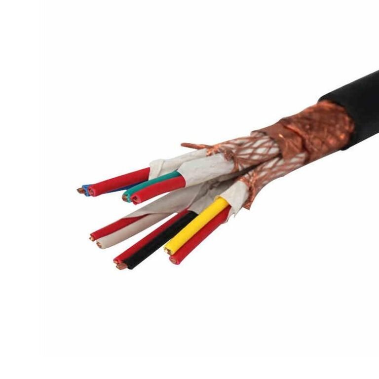
Specifying the wrong voltage rating on a control cable sounds like a minor paperwork error until you’re pulling burned insulation out of a panel at 2 a.m. because someone used a 300/500 V cable in a 450/750 V circuit. Undervoltage-rated cables don’t fail immediately — that’s what makes them dangerous. They degrade slowly, build resistance, and eventually cause nuisance trips or outright shorts that take down whole control loops. Replacement labor, unplanned downtime, and potential damage to PLCs or sensors can easily run into costs that dwarf the original cable budget several times over.
Control cables are typically rated at 300/500 V, 450/750 V, or 600/1000 V, depending on the application. The 450/750 V rating covers most general industrial control circuits. The 300/500 V class suits low-signal and instrumentation work, while 600/1000 V is specified for heavy industrial environments, power plants, and circuits where transient overvoltages are a real concern.
What most plant engineers don’t immediately think about is that the voltage rating on a control cable isn’t just about peak operating voltage — it also determines insulation thickness, temperature tolerance, and how the cable performs under fault conditions, which is where the less obvious selection decisions start to matter.
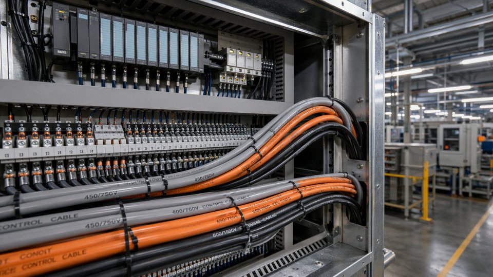
The Three Voltage Tiers of Control Cable: 300/500 V, 450/750 V, and 600/1000 V Explained
Control cable voltage ratings follow a Uo/U notation that trips up a lot of buyers the first time they see it on a datasheet. Uo is the RMS voltage between any single conductor and earth — or, where a metallic screen exists, between the conductor and that screen. U is the RMS voltage measured between any two phase conductors. So a cable marked 450/750 V can withstand 450 V to ground and 750 V phase-to-phase, simultaneously, under continuous service conditions. These are not peak values; they are sustained RMS limits.
There is also a third parameter you will see referenced in IEC documents: Um, the highest system voltage for equipment. Um defines the upper ceiling of the network in which the cable operates, accounting for voltage swells, switching transients, and supply tolerances. It effectively creates a buffer above U, and the cable’s insulation must be tested to handle Um without breaking down. In practice, Um matters most at the 600/1000 V tier, where supply fluctuations in industrial networks can push instantaneous voltages noticeably above the nominal.
300/500 V: Low-Energy Signal and Instrumentation Work
This is the lightest duty tier, and it shows in the conductor sizing — usually 0.5 mm² to 1.5 mm², though 0.75 mm² is probably the most common gauge you’ll pull off a reel in an instrument room. Applications are PLC input/output wiring, 4–20 mA instrumentation loops, low-energy relay circuits, and inter-panel signal runs where the actual circuit voltage is 24 V DC or 48 V DC. The 300/500 V rating gives you a substantial margin over those operating voltages, which is intentional — insulation integrity under fault conditions, induced voltages in bundled cable trays, and the occasional technician error all benefit from that headroom.
Conductor count here can be high. Twenty-four or thirty-seven core constructions are routine in process plant junction boxes, where a single multicore cable replaces a bundle of singles and saves tray space. Current-carrying capacity per conductor is modest at these cross-sections, so thermal loading is rarely the design driver — signal accuracy and shielding effectiveness are.
450/750 V: The General Industrial Workhorse
Most factory automation, motor control center (MCC) wiring, HVAC control panels, and switchgear internal wiring falls into this tier. Conductor cross-sections typically run 0.75 mm² up to 6 mm², with 1.5 mm² and 2.5 mm² handling the majority of general-purpose control circuits at 110 V AC or 220 V AC. This is the rating class you’ll find on most off-the-shelf control cable in European and Asian markets, and for good reason — it covers the bulk of real installations without over-engineering the insulation wall thickness.
600/1000 V: Heavy Duty, Long Runs, Harsh Environments
Power plant auxiliary control systems, substation secondary wiring, petrochemical control rooms, and mining equipment all push into this tier. Longer cable runs mean greater capacitive coupling and higher induced voltages, especially where cables run parallel to medium-voltage power feeders. The thicker insulation at 600/1000 V handles that elevated electrical stress. Conductor sizing can reach 10 mm² at this tier, though most control cores stay at 4 mm² or below — above that you’re usually crossing into power cable territory.
Mapping Rated Voltage to Your Actual System Voltage
The table below gives a practical starting point. Actual selection also depends on installation method, ambient temperature, and whether cables share a tray with power conductors — but this covers the majority of cases.
| System / Circuit Voltage | Typical Use Case | Recommended Cable Rating |
|---|---|---|
| 24 V DC | PLC I/O, sensor loops, solenoid valves | 300/500 V |
| 48 V DC | Relay logic, interposing relays | 300/500 V |
| 110 V AC | Control panel wiring, HMI circuits | 450/750 V |
| 220 V AC | General industrial control, HVAC panels | 450/750 V |
| 480 V AC | Heavy motor control, substation auxiliary | 600/1000 V |
A cable rated 450/750 V is safe for continuous use in a 220 V AC control circuit.True
The 450 V Uo rating comfortably exceeds the 220 V AC phase-to-earth voltage, and the 750 V U rating exceeds the phase-to-phase voltage. Standard IEC and most national codes confirm this match as acceptable for continuous industrial service.
One operational point worth flagging: do not select a cable rating based only on the nominal supply voltage. Always check what the circuit can see under fault conditions — a 220 V AC panel fed from a delta-connected transformer with a ground fault on one phase can present the full line-to-line voltage to earth on an unfaulted conductor. That scenario pushes you toward the 450/750 V tier at minimum, not a 300/500 V cable that looks adequate under normal conditions.
How Insulation Material Determines Voltage Capability and Temperature Performance
Voltage rating doesn’t come from the conductor — it comes from the insulation wall around it. The conductor just carries current. What keeps that current from arcing to an adjacent core, or to ground, is the dielectric strength of the insulation compound and the thickness the manufacturer applies. Get that pairing wrong, and you get premature breakdown, ground faults, or — in the worst cases — a smouldering cable harness that shuts down an entire panel.
PVC: The Workhorse With Real Limits
Polyvinyl chloride insulation runs at roughly 20–30 kV/mm dielectric strength, depending on plasticiser content, filler loading, and the specific compound grade. That range matters: a cheap general-purpose PVC and a premium flame-retardant compound are not the same material, even if both get labelled “PVC.” Continuous temperature rating sits at 70 °C for standard grades.
For most 300/500 V and 450/750 V control applications — building automation, conveyor controls, light machine tool wiring — PVC is perfectly adequate and cost-effective. The problems show up in heat, oil, or both. A cable running through a lubrication bay where hydraulic oil drips onto the tray will see PVC harden, crack, and ultimately fail tracking protection within a couple of years. Plants that ignore this usually blame “bad cable” when the real problem is material specification.
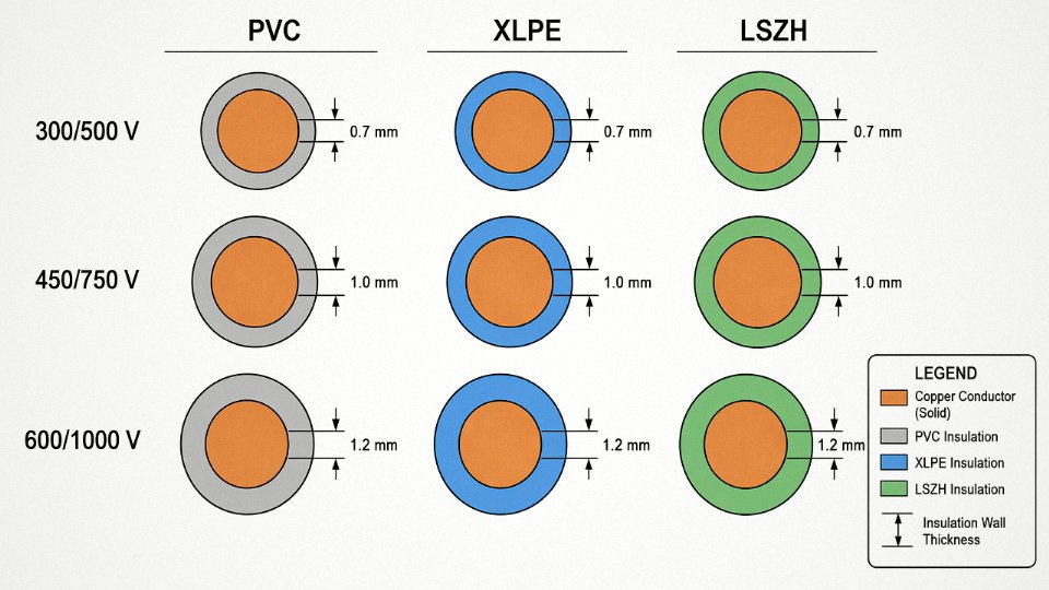
Under IEC 60227, a 1.5 mm² PVC-insulated control cable at the 300/500 V tier requires a nominal insulation wall of 0.7 mm; for a 4 mm² conductor at 450/750 V, that steps up to approximately 1.0 mm. These aren’t suggestions — they’re the minimums that underwrite the rated dielectric performance.
XLPE: More Headroom, Thinner Wall
Cross-linked polyethylene achieves dielectric strength up to around 35 kV/mm and holds it reliably to 90 °C continuous. The crosslinking process changes the polymer from thermoplastic to thermoset, which means the insulation doesn’t soften and flow under sustained heat the way PVC does. That matters enormously in tightly bundled control cable runs inside enclosures.
The practical engineering payoff: XLPE can achieve a 600/1000 V rating with a thinner insulation wall than PVC would require at the same voltage tier. For a 1.5 mm² conductor at 600/1000 V, a well-specified XLPE compound typically calls for a wall of around 0.8–1.0 mm versus what would be a heavier PVC construction. Moisture resistance is also substantially better — relevant for any outdoor tray or underground duct installation where seasonal condensation is a real factor.
LSZH, EPR, and Silicone — When the Environment Drives the Choice
Low Smoke Zero Halogen compounds carry dielectric strength broadly comparable to standard PVC, so voltage ratings mirror the same 300/500 V and 450/750 V tiers. The reason to specify LSZH has nothing to do with voltage headroom — it’s about what happens during a fire. In a tunnel, offshore platform, or public transport hub, burning PVC generates hydrogen chloride gas, which is corrosive and toxic at concentrations well below lethal levels. LSZH compounds dramatically cut both smoke density and halogen acid emission. Most offshore and rail specifications mandate LSZH regardless of cost premium.
Ethylene Propylene Rubber handles –40 °C without the insulation becoming brittle — a characteristic that makes it standard in mining equipment and marine control systems operating in cold climates. EPR supports 450/750 V and 600/1000 V ratings at 90 °C continuous, with flexibility that PVC and XLPE simply can’t match in sub-zero handling.
Silicone rubber is a different category entirely. Dielectric strength drops to roughly 15–20 kV/mm, lower than PVC. But silicone maintains its electrical and mechanical properties at 180 °C and above, which is why it appears in furnace control circuits, engine room wiring, and other high-radiant-heat environments where no other compound stays functional. You accept the lower dielectric strength because the thermal stability is irreplaceable.
XLPE insulation achieves a 600/1000 V control cable rating with a thinner insulation wall than an equivalent PVC constructionTrue
XLPE's higher dielectric strength (up to ~35 kV/mm versus ~20–30 kV/mm for PVC) and superior thermal stability under IEC standards allow a reduced wall thickness at equivalent voltage ratings, which is confirmed by IEC 60502 and IEC 60227 wall thickness tables for the respective materials.
How Compound Qualification Actually Works
Specifying an insulation type on a datasheet is the easy part. Verifying that the compound in production actually meets those claims is where manufacturers diverge. At Jinda, incoming insulation compounds go through volume resistivity testing, dielectric loss measurement, hot-set elongation (to confirm crosslink density in XLPE batches), and accelerated aging — typically 7–10 days at elevated temperature — before any compound lot is approved for production runs. Accelerated aging catches plasticiser migration in PVC grades that would otherwise show up as cracking in service after two or three years in a warm environment. It’s not glamorous work, but skipping it is how you end up with field returns that cost far more than the testing ever would.
The short version for procurement: insulation material selection isn’t just a technical footnote — it directly sets the ceiling on voltage rating, operating temperature, and service life. Matching those three factors to your actual installation conditions is worth the engineering time before you issue the purchase order.
International and Chinese National Standards That Govern Control Cable Voltage Ratings
Procurement engineers writing cable specifications without pinning them to the right standard create problems downstream — wrong insulation thickness, failed third-party audits, or cable that clears customs but fails the panel builder’s incoming inspection. Here is the standards landscape as it actually applies to control cable voltage ratings.
IEC 60227 — The Baseline for PVC-Insulated Control Cable
IEC 60227 covers PVC-insulated cables rated up to and including 450/750 V. Its structure matters for specification writing because the standard is split into numbered parts: Part 1 covers general requirements, Part 4 covers sheathed flexible cables, Part 5 covers flexible cables, and so on. Each cable type carries a designation code — for example, a typical designation like H05VV-F encodes quite a bit: “H” for harmonized, “05” for the voltage class (300/500 V), “VV” for PVC insulation and PVC sheath, “F” for flexible stranding. If you see “07” in that second position, you’re looking at a 450/750 V rated construction. That encoding is your first checkpoint when verifying a supplier’s test certificate — if the type code and the stated voltage class don’t match, something is wrong with the documentation.
The standard specifies conductor cross-sections from 0.5 mm² up to 10 mm², which covers essentially all control circuit applications. Voltage withstand tests under IEC 60227 run at 2,000 V AC for 300/500 V cables and 2,500 V AC for 450/750 V cables, applied for five minutes conductor-to-conductor and conductor-to-screen.
IEC 60245 — Rubber-Insulated Variants and Where They Differ
IEC 60245 is the parallel standard for rubber-insulated cables, also capped at 450/750 V. It covers EPR (ethylene propylene rubber) and silicone rubber types — the silicone grades are what you reach for when ambient temperatures push above +70 °C, since they’re rated to +180 °C. The test requirements are notably stricter in some respects: the bending and flexing tests for silicone constructions reflect the mechanical fragility of the insulation compared to PVC, and the hot-set test for EPR confirms crosslink density in a way that has no direct equivalent in IEC 60227. When sourcing rubber-insulated control cable for offshore platforms or steel mill environments, ask specifically for the IEC 60245 test reports rather than accepting IEC 60227 documentation by default — the tests are genuinely different.
GB/T 9330 — The Chinese National Standard
GB/T 9330 is the Chinese national standard for plastic-insulated control cables and is the primary production standard for cables manufactured domestically in China. It covers rated voltages of 450/750 V and 600/1000 V, with conductor count combinations ranging from 2 cores up to 61 cores — useful for dense instrumentation panels where you’re routing a lot of discrete signals in a single run. The standard aligns closely with IEC 60227 in its test methodology but deviates in a few practical ways: armoring construction requirements follow Chinese practice (steel tape or steel wire armor per GB specifications), and the conductor resistance tables reference slightly different temperature correction factors. For export projects, dual certification to both GB/T 9330 and IEC 60227 means the cable can be manufactured on the same production line and documented for either market.
UL 508 and CSA C22.2 No. 96 — North American Requirements
These two standards express voltage ratings as a single AC value — 600 V or 1000 V — rather than the IEC conductor-to-earth / conductor-to-conductor format. Conductor sizing follows AWG rather than mm², which creates a genuine sourcing trap. A 1.5 mm² conductor is not the same as 14 AWG; the cross-sectional areas are close but not identical, and the ampacity tables differ because NEC-based standards account for different installation methods and bundling assumptions. If you’re purchasing IEC-manufactured cable for a North American project, get explicit confirmation that the cable carries a UL listing (not just a CE mark) and that the AWG equivalence has been reviewed by the panel builder. A cable that ships with a UL mark will carry the UL file number on its surface print — check it against UL’s online database before the shipment leaves the warehouse.
CSA C22.2 No. 96 applies for Canadian projects and covers multiconductor cables for use in Class I locations, with its own conductor identification and jacket color requirements that differ from IEC practice.
IEC 61439 — Implications for Panel Wiring
IEC 61439, which governs low-voltage switchgear and controlgear assemblies, references cable voltage ratings indirectly but consequentially. The standard requires that internal wiring within an assembly be suitable for the highest voltage present, including transients. In practice, this means that control cables running inside a panel fed from a 690 V bus need to be rated at 600/1000 V, not 450/750 V, even if the control circuit itself operates at 24 V DC. Panel builders who miss this sometimes use cheaper 300/500 V cable for internal signal runs, which passes functional testing but fails a Type Test review under IEC 61439-1. It’s a small cost difference at the BOM level and a painful finding during third-party verification.
Certification Marks That Actually Matter
For general industrial supply: CCC (China Compulsory Certification) is mandatory for cables sold into the Chinese domestic market. CE marking applies for the EU but is a self-declaration framework — it does not carry the same audit weight as a listed certification. UL listing requires third-party testing and ongoing factory surveillance. For marine and offshore projects, Lloyd’s Register and DNV type approval are the standard asks, and both specify voltage rating verification as part of the approval scope. For hazardous area applications — petrochemical, grain handling, mining — ATEX certification under the IECEx scheme applies, and the cable’s voltage rating must be explicitly stated in the ATEX certificate, not assumed from the base IEC standard.
Jinda control cables hold dual certification under GB/T 9330 and IEC 60227, with CCC, CE, and Lloyd's Register approvals available across the product rangeTrue
Dual GB/T 9330 and IEC 60227 certification is achievable when the cable is manufactured to the more demanding of the two standards' requirements and tested by an accredited third-party laboratory; CCC and CE are standard requirements for export-oriented Chinese cable manufacturers, and Lloyd's Register type approval requires separate application and factory audit.
In practice, dual IEC/GB certification on a single cable construction simplifies documentation for international EPC projects considerably — the procurement team submits one set of test reports that satisfies both the Chinese FAT inspector and the overseas owner engineer. That’s a real paperwork reduction on projects where you’re managing five or six different cable types across multiple voltage ratings.
Voltage Rating Selection Logic: Matching Cable to Control System Architecture
Getting this wrong costs money in one of two ways — you over-specify and pay a 30–60 % cable cost premium across a large project, or you under-specify and deal with insulation breakdown, nuisance trips, or a control panel fire three years into commissioning. Neither outcome is acceptable, and both are avoidable with a disciplined selection process.
Step 1 — Identify Every Voltage Present on the Circuit, Not Just the Nominal
Start at the source. A 24 V DC PLC I/O loop sounds trivial, but if it shares a trunking run with 220 V AC solenoid valve wiring, the control cable in that duct must be rated for the highest voltage present. That’s a detail that gets missed on multicore bundles all the time. A 110 V AC relay circuit needs at minimum a 300/500 V rated cable in a clean indoor environment; 220 V AC solenoid circuits push you to 450/750 V; 480 V AC motor starter wiring, 600/1000 V — full stop.
DC systems have their own trap. DC is actually harder on insulation than AC at equivalent voltage because there’s no zero-crossing to interrupt partial discharge. A 600 V DC bus, which you’ll find on certain servo systems and battery storage installations, demands the same 600/1000 V rating you’d use for 480 V AC equipment, sometimes higher depending on the drive topology.
Step 2 — Apply the Derating Principle With a Real Safety Margin
The standard rule is that the cable’s Uo (conductor-to-earth rated voltage) must exceed the highest expected phase-to-earth voltage by at least 25 %. In practice I’d push that to 30–35 % on any circuit where transient suppression is minimal or the supply source impedance is low. Cheap switchgear and long cable runs from the main panel both reduce your effective protection.
Step 3 — VFDs Are a Special Case and Deserve Their Own Rule
Variable frequency drives generate voltage spikes that can reach 1.5 to 2 × the DC bus voltage, depending on rise time, cable length between drive and motor, and whether the drive uses a common mode choke. On a 480 V AC system the DC bus sits around 680 V; spike peaks can hit 1,200–1,400 V on fast-switching IGBTs without proper filtering. Running standard 450/750 V control cable in the same conduit as VFD output wiring — or using it for the drive’s own control signal cables routed near the power stage — is a reliability gamble. Specify 600/1000 V cable for any circuit physically close to VFD wiring. This isn’t over-specification; it’s acknowledging the actual electromagnetic and capacitive stress those cables experience.
Step 4 — Installation Environment Raises or Lowers the Effective Stress
A cable buried directly in damp soil experiences sustained dielectric stress from moisture ingress at the jacket, regardless of what the nominal circuit voltage is. Proximity to other energised cables in a dense tray adds capacitive coupling. Conduit installations in outdoor enclosures cycle through temperature and humidity daily, accelerating insulation aging. As a general guide: direct buried and submarine applications should always use the next voltage tier up from the minimum electrical requirement; free-air tray installations in a dry, climate-controlled electrical room can stay at the minimum adequate rating.
Step 5 — Long Runs Complicate the Picture
For runs over roughly 200 m in a process plant — instrumentation home-runs, remote field junction boxes, perimeter fence control loops — the voltage drop constraint often forces you to a larger conductor cross-section anyway. A larger conductor cross-section almost always comes in a higher voltage-rated construction because cable manufacturers optimise their insulation wall thickness to the conductor size range. Check the voltage drop figure independently; don’t assume the cable you chose for electrical stress automatically solves your drop budget.
A 25–35 % Uo safety margin above peak phase-to-earth voltage is standard engineering practice for control cable voltage selectionTrue
IEC 60364 and common industrial engineering practice both support selecting cable with rated voltage exceeding the maximum sustained conductor-to-earth voltage; the specific margin accounts for transients, aging, and installation stress factors that reduce effective insulation performance over the cable's service life.
Step 6 — Panel Hardware Must Match the Cable Rating
A 600/1000 V cable terminated on a terminal block rated only to 400 V creates a compliance gap that will fail inspection and, more practically, creates a weak point in the insulation system. Check that terminal blocks, cable glands, connectors, and any inline junction boxes carry a voltage rating equal to or greater than the cable itself. Phoenix Contact and Weidmüller both publish voltage ratings on their terminal block datasheets; Roxtec and similar gland manufacturers do too. This step gets skipped in panel builds more often than it should.
Over- and Under-Specification: The Real Cost
Blanket use of 600/1000 V cable across a project — every loop, every signal cable, every PLC I/O run — is a common “safe” default that procurement managers sometimes push. On a mid-size process plant with 15,000–25,000 m of control cable, the cost difference between 450/750 V and 600/1000 V construction is typically 20–45 % per metre depending on core count and insulation material. That’s not a rounding error.
Under-specification is worse. Insulation breakdown on a 24 V signal cable that was incorrectly run with 480 V circuits doesn’t always fail catastrophically on day one. It degrades over 18–36 months, produces intermittent signal faults that are genuinely difficult to diagnose, and eventually causes a hard failure — often at the worst possible operational moment.
The selection logic reduces to this: identify peak voltage including transients, apply a 25–35 % Uo margin, check the installation environment, verify the hardware chain, and only then confirm the voltage tier.
Shielding, Armoring, and Their Interaction with Voltage Rating in Control Cables
A lot of confusion in the field comes from treating shielding and armoring as interchangeable concepts, or assuming that adding either one somehow upgrades the cable’s voltage class. Neither is true, and getting this wrong leads to real problems — insulation breakdown, circulating currents, ground faults during commissioning, or a cable that passes the desk review and then fails the first spark test.
Why Shielding Gets Specified in the First Place
Control cables run alongside power conductors, VFD output cables, and contactor wiring — all of which are prolific EMI sources. A 15 kW VFD switching at 4–16 kHz can inject enough common-mode noise into an unshielded signal pair to corrupt a 4–20 mA loop or trigger nuisance trips on a PLC input. The shield — whether foil or braid — intercepts that radiated field and diverts it to ground before it reaches the signal conductors.
The shield does not change the conductor-to-conductor rated voltage. A 450/750 V cable with an overall foil shield is still a 450/750 V cable. What shielding does introduce is a new parameter: conductor-to-shield voltage. If the shield is improperly grounded or floating, it can sit at an indeterminate potential relative to the conductors inside it, which creates a voltage stress the insulation between conductor and shield has to handle continuously. In practice, that stress is small in a well-grounded system, but in a plant where ground loops are already messy — and many plants are — it is not negligible.
Foil Shield vs. Braided Shield: Not Just a Performance Difference
Foil (typically aluminum-polyester laminate) gives 100 % surface coverage and low capacitance, which is why it dominates instrumentation and signal circuits at 300/500 V and 450/750 V. The trade-off is mechanical fragility; the foil tears if the cable flexes repeatedly, and drain wire continuity becomes unreliable over time in dynamic applications.
Braid shield — copper or tinned copper, typically 85–95 % optical coverage — is mechanically tougher and presents a lower-impedance path to ground at higher frequencies. At 600/1000 V in heavy industrial control, motor protection panels, and substation secondary wiring, braid is the more common choice. It handles the vibration and the rougher termination work that happens in those environments.
Grounding the Shield: Where Most Installation Errors Occur
Single-point grounding at the receiving end (the control panel or marshalling cabinet) is the standard for most instrumentation circuits. It prevents the shield from becoming a conductor for ground-loop currents that flow between panels at different ground potentials. Multipoint grounding is used where high-frequency immunity is the priority — certain fieldbus and data cable applications — but it requires genuinely equalized ground potentials across all termination points, which is harder to guarantee in a large plant.
When a shield is grounded at both ends with a measurable potential difference between those grounds (not unusual in a large facility — 1–5 V is common, occasionally more), circulating current flows through the shield. That current generates a voltage drop along the shield conductor, which translates directly into a voltage differential between the shield and the cores it surrounds. It is a real, continuous electrical stress added on top of the rated operating voltage.
Improper multipoint shield grounding can induce circulating currents that add measurable voltage stress to core-to-shield insulation, independent of the cable's rated voltage class.True
Ground potential differences between two grounding points drive current through the shield conductor. Ohm's law applied to the shield resistance and the flowing current produces a voltage gradient along the shield, creating a core-to-shield voltage that the insulation must withstand continuously. This is documented in IEC grounding guidance and widely confirmed in industrial field experience.
Steel Wire Armor and Steel Tape Armor: Mechanical Protection, Not Voltage Upgrade
SWA (Steel Wire Armored) and STA (Steel Tape Armored) control cables are specified for direct burial, cable trench installations, or wherever crushing, rodent damage, or pulling tension is a concern. The armor is a separate concentric layer — it carries fault current back to the source during an earth fault, which is useful for protection relay operation — but it has nothing to do with the cable’s basic rated voltage. A 450/750 V SWA control cable is a 450/750 V cable. The armor does not add dielectric strength between conductors.
Mining and offshore applications routinely specify double-armored cables — a layer of steel wire over an inner bedding, then another layer — primarily because abrasion, water ingress, and mechanical impact are all worse in those environments simultaneously. Cables in those applications are typically rated 600/1000 V not because the armor demands it, but because the electrical environment — higher fault energies, longer cable runs, less controlled grounding systems — does.
How Layering Sequence and Production Testing Tie It Together
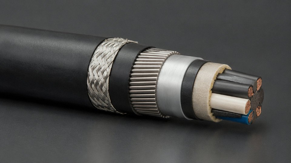
In Jinda’s shielded and armored control cable construction, the layering goes in a specific sequence for a reason: core insulation, then cabling with fillers to maintain a round cross-section, inner sheath, shield (foil or braid depending on specification), armor if required, then outer sheath. Each layer serves a defined function, and quality control checkpoints happen at each transition — not just at the finished cable stage.
Individual insulated cores for 450/750 V cables are spark-tested at roughly 2 kV AC during extrusion, catching pinhole defects in the insulation before the core ever gets cabled up. After cabling and sheathing, the finished cable undergoes a high-voltage test — typically 4 kV AC for 600/1000 V-rated cables — in line with IEC and GB/T requirements. The exact test voltage depends on the rated voltage class and the applicable standard; 2 kV and 4 kV are the common benchmarks, not arbitrary figures.
Getting shielding and armoring specified correctly — and then installed correctly — closes a gap that causes more commissioning headaches than most engineers expect.
Real-World Voltage Rating Failures: Causes, Consequences, and Prevention
Voltage ratings are not bureaucratic paperwork. They exist because insulation fails in specific, predictable ways when pushed beyond design limits — and the failure mode is rarely gentle.
Roughly 12–18 % of reported industrial cable failures involve some form of voltage rating mismatch, based on maintenance survey data compiled across IEEE and CIGRE failure studies. That range shifts toward the higher end in older plants where cable stores are poorly labeled and maintenance crews pull whatever is on the shelf.
Approximately 12–18% of industrial cable failures are attributable to voltage rating mismatch, based on IEEE and CIGRE maintenance survey data.True
IEEE and CIGRE both publish periodic reliability and failure-mode surveys for industrial electrical systems; voltage rating mismatch is consistently cited as a significant contributor, though the exact percentage varies by industry sector and plant age.
VFD Motor Control Circuits: The Most Common Underrating Mistake
Variable frequency drives do not produce clean sinusoidal voltage. The switching transients from IGBT-based drives generate repetitive voltage spikes — typically 1.5 to 2 times the DC bus voltage at the motor terminals, and sometimes higher depending on cable length and rise time. In a 480 V AC system, that means transient peaks routinely hitting 1,200–1,500 V in the leads between the drive and motor terminal box.
A 300/500 V PVC-insulated control cable has a dielectric strength that handles nominal voltage comfortably. It does not handle 18 months of repetitive 1,200 V spikes. The insulation degrades progressively through partial discharge erosion, and the failure usually shows up first at the motor terminal box where mechanical stress compounds the electrical stress. The fix is straightforward: specify 600/1000 V cable for any VFD circuit, full stop. Some engineers also move to XLPE insulation here because its higher dielectric strength gives additional margin.
Direct-Buried Cable and the Moisture Degradation Problem
This failure takes years to develop, which is partly why it gets ignored until it’s expensive. PVC insulation absorbs moisture slowly; aged PVC — say, after 8–12 years in direct-burial conditions — can have its effective dielectric strength reduced by 20–35 % depending on soil chemistry, seasonal water table variation, and original compound quality. A 450/750 V rated cable running at 380 V nominal looks fine on paper. But after a decade of groundwater exposure without a proper moisture-resistant outer sheath, partial discharge activity develops in the insulation at voltage levels it should handle without trouble.
The lesson is not simply “use higher voltage cable.” It’s to specify direct-burial construction with a moisture-blocking sheath — polyethylene or a laminated barrier layer — and build in at least one voltage tier of margin for any underground run expected to last beyond a decade. Seasonal flooding makes this worse. In practice, a cable trench in a coastal or low-lying industrial area is a very different environment from a dry inland site.
Shield Grounding: The Failure That Isn’t a Voltage Rating Failure (Until It Is)
A process plant installs shielded 450/750 V control cable for 4–20 mA analog loops — correct voltage rating, correct shielding, correct installation depth. The commissioning team grounds the shield at both ends. Within weeks, nuisance trips start appearing on flow transmitters and level sensors. Measured shield-to-earth voltage on several loops is 8–15 V at 50 Hz.
The cable’s voltage rating is fine. The signal integrity is destroyed because the shield is carrying circulating ground current rather than acting as a Faraday barrier. In circuits close to large motors or transformers, this induced voltage can also cause differential stress across the insulation of very low-signal cables. Ground the shield at one end only — almost always the control panel end — and leave the field end floating.
Substation Substitution: A Maintenance Hazard
This one is avoidable and still happens regularly. A maintenance crew replacing a failed section of 600/1000 V auxiliary control cable in a substation grabs a reel from the cable store. The outer jacket color looks similar. The cable installs cleanly and passes a 2.5 kV insulation resistance test. The problem is that 300/500 V cable can pass that IR test at ambient conditions. It cannot survive the switching transients that occur during bus transfer operations — transients that routinely reach several kilovolts in substation auxiliary circuits.
Catastrophic insulation failure during a switching event is not a maintenance nuisance. It can trigger protective relay operations, damage control equipment, and create a genuine safety incident.
The prevention is not technically complex. Cable schedules should specify voltage rating explicitly on every line. Physical reels in stores should be labeled with voltage class in large print, and ideally color-coded by tier — some plants use colored end-caps on reels. Bill-of-materials discipline has to be enforced; in my experience, the breakdown usually happens when someone is under time pressure at 2 a.m. during an outage.
Preventive Measures Worth Implementing
Periodic insulation resistance testing — Megger testing at appropriate voltage for the cable class — should be on a scheduled maintenance plan, not just performed after an incident. For critical circuits above 1 kV, partial discharge testing provides earlier warning of degradation than simple IR measurement. Cable schedule management, explicit voltage-tier labeling, and strict substitution controls during maintenance are the unglamorous administrative controls that prevent the failures described above. They cost almost nothing compared to the downtime they prevent.
Control Cable Voltage Ratings in Hazardous Area and High-Temperature Industrial Applications
Standard voltage tier logic — pick 300/500 V, 450/750 V, or 600/1000 V based on your circuit — breaks down the moment you walk into a hydrocarbon processing unit, a longwall mining face, or a steel melt shop. Those environments layer on requirements that a basic voltage rating simply doesn’t cover, and getting the specification wrong has consequences that go well beyond a nuisance trip.
ATEX, IECEx, and What the Cable Actually Certifies
Here’s a point that regularly causes confusion on procurement checklists: the cable itself does not carry an ATEX or IECEx certificate for its voltage rating. The explosive atmosphere certification belongs to the cable entry system — the gland, the conduit seal, the Ex-d or Ex-e enclosure through which the cable passes. That said, the cable must still be rated for the circuit voltage it carries, and Zone 1 or Zone 2 installations will typically demand that the cable also meet flame-propagation requirements (IEC 60332-1 at minimum, often IEC 60332-3 for bunched installations) and use a low-smoke zero-halogen sheath in occupied or confined areas.
In practice, for a Zone 1 gas detection and shutdown panel, you will typically specify a 450/750 V LSZH-sheathed, screened control cable, run it through certified Ex-e glands, and document the full cable entry assembly — not the cable alone — for your hazardous area dossier.
Intrinsically Safe Circuits: Low Application Voltage, Non-Trivial Insulation Demand
Intrinsically safe (IS) circuits in instrumentation loops commonly operate below 28 V DC — sometimes as low as 12 V. An engineer seeing that might assume the insulation requirement is correspondingly relaxed. It isn’t. IEC 60079-14 requires IS cables to withstand a 500 V DC insulation resistance test, and the rated voltage of the cable itself remains 300/500 V. The standard also mandates physical separation from non-IS cables — either segregated cable trays, a minimum separation distance, or a grounded metallic partition — because an induced voltage from an adjacent 450/750 V control run could, in theory, compromise the intrinsic safety parameters. This is one area where a plant layout review matters as much as the cable datasheet.
Mining: Composite Cables and the 450/750 V Floor
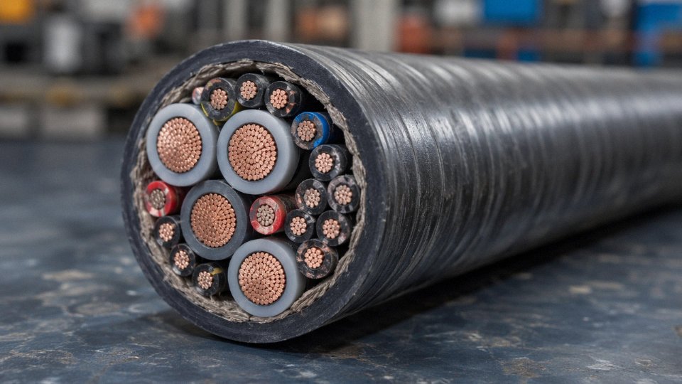
Trailing cables for continuous miners and longwall shearers are a class apart. Under IEC 60502 and most national mining standards, the power cores of these composite cables are rated 600/1000 V or 1.9/3.3 kV, and the control cores running inside the same sheath must be rated to at least 450/750 V. The reason is straightforward: a damaged power core in a wet mine environment can capacitively or resistively couple to adjacent control cores. Undersizing those control cores to 300/500 V creates a failure path you genuinely don’t want several hundred meters underground.
Steel Plants and Furnace Environments: Temperature Is the Dominant Variable
Near induction furnaces and electric arc furnaces, induced voltages on unshielded cable runs can reach levels that stress 300/500 V insulation over time. The bigger threat, though, is thermal. Ambient temperatures within 5–10 meters of an EAF taphole can easily reach 90–120 °C intermittently, which eliminates standard PVC-insulated cable as an option. The usual specification in those zones is a silicone rubber or ethylene propylene rubber (EPR) insulated 450/750 V screened control cable, sometimes with an additional fibreglass braid or thermal wrap, and a continuous temperature rating of at least +150 °C. Silicone-insulated cables also hold their flexibility at low winter temperatures, which matters in plants that operate year-round in northern climates.
Offshore and Marine: 600/1000 V, Flame-Tested, Mud-Resistant
IEC 60092-376 governs instrumentation and control cables for ships and offshore platforms. The rated voltage is typically 600/1000 V, the outer sheath must resist seawater, hydraulic fluid, and drilling mud, and the cable assembly must pass IEC 60332-3 Category A or B flame spread testing. LSZH sheathing is standard — on an offshore platform you cannot afford halogen-acid smoke filling an enclosed module during a cable fire. Armoring with a stainless steel braid rather than galvanized steel wire is increasingly specified in marine installations where corrosion lifetime matters.
Nuclear I&C Cables: Voltage Capability After Decades of Radiation
Nuclear instrumentation and control cables operate under IEEE 383 and IEC 60780, which add radiation resistance qualification and accelerated aging simulation to the usual voltage requirements. Cables must demonstrate that they maintain their rated voltage capability — typically 600 V class — after cumulative radiation doses of 200 Mrad or more and thermal aging equivalent to 40-plus years of service. This is not a datasheet claim; it requires documented qualification test reports. Cross-linked polyethylene or EPR insulation formulations with radiation-stabilizing additives are the standard choice; plain PVC degrades under radiation exposure and is not acceptable.
An IS (intrinsically safe) circuit cable only needs insulation rated for its actual operating voltage (e.g., 12 V DC), so a lower-rated cable may be used.False
IEC 60079-14 requires intrinsically safe cables to pass a 500 V DC insulation test regardless of the low application voltage. The cable's rated voltage remains 300/500 V. Using a substandard cable risks compromising the IS circuit's safety parameters.
How Jinda Addresses These Segments
Jinda’s specialized cable divisions produce control cables covering each of these application areas, including LSZH-sheathed screened cables for hazardous area instrumentation, EPR and silicone-insulated variants for high-temperature furnace environments, composite mining trailing cables to IEC 60502, and flame-retardant marine control cables to IEC 60092-376. Certificates and qualification test reports are available by product line; for nuclear-grade or ATEX-adjacent specifications, the technical team can review the application parameters and confirm the appropriate product family before an order is placed — which, in these segments, is time better spent upfront than troubleshooting in the field.
Frequently Asked Questions About Control Cable Voltage
Can I use a 450/750 V control cable on a 480 V AC circuit?
Technically, this sits in an uncomfortable gray zone. In a 480 V wye system, phase-to-earth voltage is roughly 277 V — well within the 450 V Uo rating. But line-to-line voltage hits 480 V, and Uo of 450 V means the cable was not designed to handle that continuously as a conductor-to-conductor stress. If wiring practice or a fault condition ever places full line voltage across two conductors in that cable, you are operating outside the rated envelope.
The correct choice for 480 V circuits is a 600/1000 V cable, full stop. The cost delta between the two tiers is modest — usually 8–18% per meter depending on conductor cross-section and construction — and it buys you genuine compliance rather than a marginal pass on paper.
What does the slash mean in 300/500 V?
The number before the slash is Uo: the rated RMS voltage from any conductor to earth (or to the metallic screen if one is present). The number after is U: the rated RMS voltage between any two conductors. Both values must equal or exceed the actual voltages present in the installation. Specifying only one and ignoring the other is a common mistake in procurement documents, especially when engineers are more accustomed to single-voltage transformer ratings.
Is control cable voltage the same as signal cable voltage?
Signal cables — 4–20 mA loops, thermocouple extensions, RS-485 data lines — carry millivolt or low-voltage signals in normal operation. Their rated voltage (typically 300/500 V) is not describing the signal itself. It describes the insulation’s ability to withstand fault voltages from adjacent power circuits. In a cable tray where control and power cables share space, a ground fault or insulation breakdown on a nearby circuit can impose full system voltage on the signal cable’s insulation for the duration of the fault. The 300/500 V rating is what protects against that scenario, not the signal level.
How do I test whether my existing control cable still meets its voltage rating?
Use a calibrated insulation resistance tester — a Megger or equivalent. For 300/500 V cables, apply 500 V DC; for 600/1000 V cables, use 1000 V DC. Insulation resistance below 1 MΩ·km is a clear warning sign of moisture ingress, thermal aging, or mechanical damage. IEC 60364-6 sets out commissioning and periodic verification test protocols. In practice, cables in wet or chemically aggressive environments should be tested annually; in clean, climate-controlled panels, every three to five years is usually adequate.
IR values below 1 MΩ·km on a control cable insulation resistance test indicate degradation requiring immediate investigation before re-energizing the circuit.True
IEC 60364-6 and general industry practice treat 1 MΩ·km as the minimum acceptable threshold for insulation resistance in LV control and power cables. Values below this indicate moisture ingress, thermal damage, or insulation breakdown.
Does the number of cores affect the voltage rating?
The rated voltage applies per core, not per cable. A 19-core 450/750 V cable has the same per-core voltage rating as a 4-core 450/750 V cable. Where core count matters is in insulation wall thickness — standards like IEC 60227 specify that wall thicknesses must meet inter-core as well as conductor-to-earth withstand requirements, and with tightly packed cores, manufacturers need to hold tighter dimensional tolerances. The rated voltage does not change, but the manufacturing discipline required to achieve it consistently gets harder as core count rises.
What voltage rating should I specify for a control cable running parallel to a 6.6 kV power cable?
You do not need to uprate the control cable’s voltage class just because of proximity to a 6.6 kV circuit. The HV cable’s own insulation system contains its electric field. What you do need is a shielded control cable — braid or foil plus drain wire — and adherence to the minimum separation distances in IEC 60364-5-52. The hazard from nearby HV cables is electromagnetic interference and induced noise, not a direct voltage stress on the control cable’s insulation.
How does Jinda mark its control cables to identify the voltage rating?
Jinda prints the rated voltage (for example, 450/750 V), the applicable standard (GB/T 9330 for domestically specified cables, or IEC equivalents for export orders), and the full cable type designation on the outer sheath at intervals not exceeding 500 mm. Export cables destined for specific markets carry the relevant certification marks — CE marking for EU customers, and other country-specific conformity marks where required. If you receive a reel and the sheath markings are absent or inconsistent, treat that as a non-conformance before the cable goes anywhere near a panel.
What is the maximum DC voltage allowed on a cable rated for AC voltage?
Per IEC 60227, a cable with an AC rating of 450/750 V may generally be used on DC systems at up to roughly 1.5× the AC rated voltage — placing the allowable DC range somewhere between 675 V and 1,125 V depending on system configuration and how the voltage is measured. The reasoning is straightforward: for the same peak voltage, DC produces lower dielectric stress than AC because there is no capacitive charging cycle. That said, always verify against the specific cable construction datasheet and the applicable installation standard for your region, since some national codes apply different multipliers.
Specifying and Sourcing the Right Voltage-Rated Control Cable for Global Projects
Getting the voltage rating right in the design office is one thing. Translating that into a purchase specification that a factory in another country can actually manufacture to — and that your inspection team can verify — is a different discipline entirely. Plenty of projects have received cable that was built to a plausible-sounding spec but lacked a critical certification, used the wrong insulation compound for the site temperature, or arrived on drums that kinked the outer cores during unloading. All of that starts with a weak specification.
Writing a Cable Specification That Leaves No Ambiguity
A complete control cable specification needs, at minimum: rated voltage expressed as Uo/U (e.g., 450/750 V), number of cores and nominal cross-section per core (e.g., 12 × 1.5 mm²), insulation material and grade (PVC to IEC 60227, XLPE, or silicone rubber for high-temperature service), shielding type if required (individual pair, overall braid, or foil with drain wire), armor type (steel wire armor, steel tape, or unarmored), outer sheath material and color, operating temperature range, applicable standard, and required certification or approval marks. Miss any one of these and you’re relying on the manufacturer to make assumptions — which they will, and not always conservatively.
Rated voltage is the field that gets abbreviated most carelessly. Writing “600 V control cable” without specifying the Uo/U convention can mean different things to an IEC factory and a UL-certified plant. Be explicit.
Voltage Rating and Project Geography
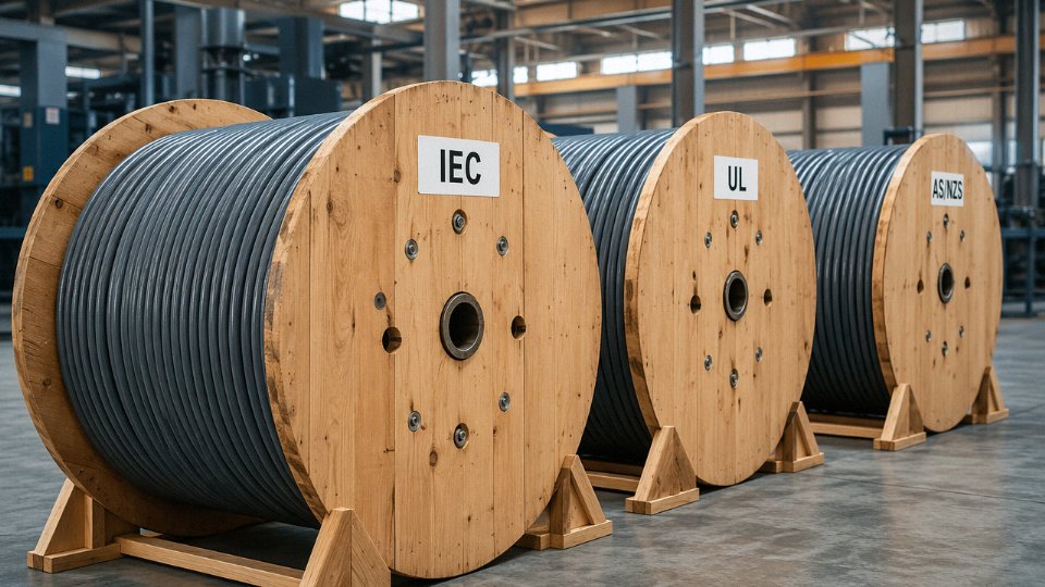
The dominant IEC framework used across Europe, the Middle East, and most of Asia calls out 450/750 V and 600/1000 V as the standard control cable voltage classes. North American projects — and export projects destined for facilities managed by North American EPCs — typically specify 600 V class under UL 508 or CSA C22.2, which uses a single-voltage designation rather than the Uo/U pair. Australian and New Zealand installations follow AS/NZS 3000 with its own wiring rules and cable selection criteria; in practice the voltage classes align roughly with IEC, but the certification pathway is separate and the sheath color conventions differ.
Running a single order across two or three of these regulatory zones is where most procurement headaches originate. Jinda’s production lines are configured to build the same core construction — same copper conductor, same insulation compound, same armor lay — to IEC, GB, and select UL/CSA requirements within a single manufacturing run, with the appropriate certification marks applied per the destination market. That matters for project owners who are supplying a facility that spans multiple national code jurisdictions, or for distributors maintaining a consolidated stock.
Lead Times and Production Capacity
For standard 450/750 V multi-core control cable in common configurations (roughly 4 to 37 cores, 0.75 to 2.5 mm² per core), lead times from Jinda’s five production bases typically run 15 to 25 days for orders under 500 km of cable, depending on core count, shielding complexity, and current line loading. Larger or more specialized orders — say, 600/1000 V XLPE-insulated SWA cable with individual pair shielding — will naturally run longer, and quoting a realistic schedule upfront is something any serious supplier should do rather than defaulting to an optimistic number.
For ongoing infrastructure programs, a dedicated project supply agreement locks in production slot priority, agreed drum configurations, and staged delivery scheduling. That arrangement is worth pursuing if your project has a multi-year cable draw-down.
Quality Documentation Package
A tier-1 supplier should provide, without special request: factory test reports (FTR) per IEC 60227 covering spark test pass/fail records, insulation resistance values, and AC voltage withstand results; material certificates for copper conductors traceable to IEC 60228 or ASTM B3; and compound batch certificates for the insulation and sheath. Third-party inspection through SGS, Bureau Veritas, or Intertek can be arranged at point of production — useful for projects where the end-client requires witnessed testing or where the shipping distance makes remediation expensive.
Jinda provides factory test reports per IEC 60227 including spark test, insulation resistance, and voltage withstand results as standard documentation with each order.True
This aligns with IEC 60227 manufacturer testing requirements and is confirmed as standard practice for Jinda's production and QA process.
Packaging, Drums, and a Detail Most Specs Ignore
Standard IEC wooden drums run from D250 up to D800 depending on cable diameter and reel length. Sea freight is generally tolerant of larger, heavier drums — up to roughly 3 to 5 tonnes gross depending on the shipping line and port handling equipment — whereas air freight imposes strict weight limits that usually push toward smaller reels or flat-pack coils for short lengths. Drum lay-out direction matters: cable that is pulled off a drum against the lay can kink, and a sharp kink in a multi-core control cable doesn’t just look bad — it concentrates mechanical stress on the insulation precisely where you least want it, creating a latent dielectric weakness that may not show up until the installation has been energized for a season or two.
Specify drum rotation direction on your purchase order. It takes ten seconds and has saved more than one site team from a very tedious fault-finding exercise.
Getting Technical Support Before You Commit
Jinda’s R&D and technical support division has operated alongside production since the company’s founding in 1987, which means the engineers handling pre-order consultations have access to the same people who actually set up the production parameters. Free voltage selection consultations, sample cable for client testing, and engineering drawings formatted for project approval packages are available to international buyers before any order is placed — useful when you’re preparing a vendor technical data sheet for client or EPC sign-off. With customers across 50-plus countries, the team is practiced at working through time-zone gaps and project document requirements that vary significantly by region.