Specify the wrong wire type on a bill of materials and you might not find out until a transformer runs hot, a control panel fails inspection, or a batch of finished assemblies gets scrapped at incoming QC. It happens more than procurement teams like to admit — a stranded conductor spec’d where a solid one was needed, bare copper pulled into a corrosive environment, aluminum crimped with fittings rated only for copper. Each of those mistakes carries a cost: unplanned downtime typically runs anywhere from a few hundred to several thousand dollars an hour depending on the process, and re-pulling wire through conduit in an operating facility costs multiples of what the original installation did.
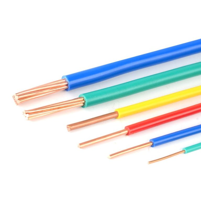
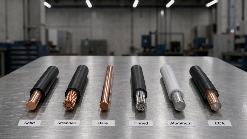
The six main types of wire are: solid wire, stranded wire, bare wire, tinned wire, aluminum wire, and copper-clad aluminum (CCA) wire. Each is defined by its conductor geometry, material, or surface treatment — and the right choice depends on the application’s flex requirements, current load, environmental exposure, termination method, and total installed cost, not just the price per meter on the purchase order.
What makes this genuinely complicated — and what most sourcing guides gloss over — is that these six categories overlap and interact. A wire can be stranded and tinned and copper at the same time. The category labels are starting points for a specification conversation, not finished specs themselves. Understanding what actually distinguishes each type, and where the tradeoffs bite you in practice, is what separates a cable schedule that survives commissioning from one that generates change orders.
Type 1 — Solid Wire: Construction, Ratings, and Where It Excels
Solid wire is exactly what it sounds like — a single, unbroken metal rod drawn down to a target diameter. No twisting, no bundles, no air gaps between strands. Just one conductor running the full length of the cable. That simplicity is both its biggest strength and the source of most of the procurement mistakes I’ve seen with it.
How the Drawing Process Actually Matters
Starting from a rod — typically 8 mm copper rod or 9.5 mm aluminum rod cast at the rod mill — the conductor is pulled through a series of progressively smaller tungsten carbide dies. Each pass reduces the cross-section by somewhere around 15–25%, depending on the alloy and the die angle. This cold-working elongates the metal’s grain structure, which is good for tensile strength but introduces work hardening. Annealing (heating after drawing, usually at 300–500°C depending on target temper) partially restores ductility, but the wire still ends up significantly stiffer than stranded constructions. That stiffness matters on the installation floor.
The drawing process also directly affects conductivity. Well-controlled multi-pass drawing on properly annealed copper can preserve resistivity close to the theoretical benchmark of around 1.68 × 10⁻⁸ Ω·m at 20°C. Cheaper material, rushed annealing, or recycled copper with impurity spikes can push that figure up by a few percent — which sounds trivial until you’re sizing a 400 A feeder.
Electrical Characteristics
The electrical case for solid wire is real. Because there are no inter-strand voids, the effective cross-section is fully utilized. A solid AWG 12 copper conductor runs roughly 1.588 Ω per 1,000 ft at 20°C; the equivalent stranded AWG 12 sits slightly higher — typically 1.62–1.65 Ω/1,000 ft depending on strand lay and compaction. At AWG 14, solid copper runs approximately 2.525 Ω/1,000 ft. These differences become meaningful in long-run branch circuits where cumulative voltage drop is already tight.
Solid wire has lower DC resistance per unit length than stranded wire of the same AWG, due to the absence of inter-strand air gaps.True
The geometric fill factor of stranded conductors is typically 0.75–0.93 depending on strand count and compaction, meaning a small fraction of the nominal cross-section is air. Solid wire achieves ~1.0 fill factor, giving marginally lower DC resistance for a given AWG designation.
Mechanical Trade-Offs and Bend Radius
Solid wire does not like to be flexed repeatedly. Once, twice, maybe a few times during a careful installation — fine. But run it to a motor terminal that vibrates, or route it through a panel door that opens and closes daily, and you will eventually find a cracked conductor. Work hardening from repeated bending concentrates stress at the same point each cycle. That’s a fatigue failure waiting to happen, usually at the terminal lug, usually after 6–18 months of service.
For installation, the minimum bend radius is typically 5× the conductor diameter. For AWG 12 solid copper (roughly 2.05 mm diameter), that’s about 10 mm. In practice, electricians often exceed this bending tighter into junction boxes, which is fine for a single bend during installation but not for anything dynamic.
Insulation Types and Ratings
The most common insulation systems on solid building wire are THHN, THWN-2, and XHHW-2. THHN is rated for 90°C in dry locations and 600 V; THWN-2 adds wet-location suitability at the same 90°C and 600 V. XHHW-2 handles 90°C in both wet and dry environments and is frequently specified for underground raceways. All three are compatible with solid copper in standard building wire gauges (AWG 14 through AWG 6 cover most branch circuit and feeder work).
Typical Application Zones and Ampacity
Solid wire dominates residential and light commercial branch circuit wiring — NEC Article 334 covers NM-B cable which is nearly always solid through AWG 10. Control panels with fixed point-to-point wiring use solid conductors specifically because they hold shape in terminal blocks without splaying. Grounding electrode conductors are another reliable application; the NEC permits solid copper GECs up to AWG 4 in most residential work.
| AWG | Typical Conductor Dia. (mm) | NEC 310.15 Ampacity (Cu, 60°C) | Common Use |
|---|---|---|---|
| 14 | 1.63 | 15 A | Lighting branch circuits |
| 12 | 2.05 | 20 A | Receptacle branch circuits |
| 10 | 2.59 | 30 A | Appliance circuits, HVAC |
| 8 | 3.26 | 40 A | Range, dryer, sub-feeders |
| 6 | 4.11 | 55 A | Small feeder runs |
Ampacity depends on conduit fill, ambient temperature, and insulation type — the above assumes no more than three current-carrying conductors in a raceway at 30°C ambient.
The Procurement Pitfalls Worth Flagging
Two patterns show up repeatedly in field problems. First: someone specs solid wire for a connection to a pump or small motor because it’s cheaper per foot, and within a year they’re chasing an intermittent fault caused by a fractured conductor at the terminal. Stranded wire exists for a reason. Second, and more expensive: aluminum solid wire in a high-current feeder (say, 100 A or above) specified without AL-rated compression lugs or anti-oxidant compound. Aluminum oxide forms quickly on freshly cut aluminum, increases contact resistance, generates heat, and in a worst case initiates a connection fire. The wire itself may be correctly sized; the termination hardware is the gap.
Solid wire is genuinely the right choice for fixed, non-flexing installations where cost, DC resistance, and ease of termination in screw-type terminals matter. Use it outside those conditions and it will eventually remind you why stranded wire was invented.
Type 2 — Stranded Wire: Flexibility Classes, Strand Counts, and High-Cycle Applications
Stranded wire is exactly what the name says: multiple individual conductors helically wound together to form a single composite conductor. That’s the whole trick. By dividing the cross-section into many smaller wires instead of one solid rod, you distribute bending stress across dozens — sometimes hundreds — of individual strands, each of which deflects far less per flex cycle than a solid conductor of equivalent gauge would.
IEC 60228 Flexibility Classes and What the Numbers Actually Mean
IEC 60228 is the framework most international projects reference. Class 1 is solid (covered in the previous section). Class 2 is standard stranded — seven strands for smaller cross-sections, nineteen or more for larger ones, designed primarily for fixed installation. Class 5 is flexible, intended for portable equipment and frequent movement. Class 6 goes further still: extra-flexible, with the finest individual strand diameters in the family.
The practical difference shows up fast when you put a number to it. A Class 2 copper conductor at 1.5 mm² typically uses 7 strands of roughly 0.53 mm diameter each. The same cross-section in Class 5 uses around 30 strands of approximately 0.25 mm. Smaller strand diameter means lower bending stress at the outer fibers of each strand during a flex cycle — the fatigue mechanics here follow basic beam theory, and the improvement is not marginal. Class 5 cable in a drag chain application usually achieves a minimum dynamic bend radius of about 7.5× the cable outer diameter; Class 2 in the same installation would start cracking insulation and work-hardening the conductors within a fraction of the cycle count. Class 6, used in robotics and continuous-flex tracks, can be rated to 10 million flex cycles or beyond when correctly specified with the right insulation compound.
Skin Effect and the Litz Wire Caveat
One thing that catches people off guard: stranded wire is not automatically better at high frequencies. Above roughly 10 kHz — relevant in inverter outputs, induction heating leads, and power electronics generally — inter-strand capacitance and proximity effect can actually increase effective AC resistance compared to solid wire of the same cross-section. Standard Class 5 or Class 6 stranding does nothing to solve this. If you’re running high-frequency current, you need Litz wire, where each strand is individually insulated and the bundle is geometrically arranged to equalize current distribution. Using ordinary stranded cable in a 20 kHz inverter lead and wondering why it runs warm is a real troubleshooting scenario.
Standard stranded wire (IEC 60228 Class 5 or Class 6) reduces AC resistance at high frequencies compared to solid wireFalse
Standard stranded construction does not reduce skin effect or proximity effect losses. At frequencies above roughly 10 kHz, inter-strand coupling can increase effective AC resistance. Only purpose-built Litz wire — with individually insulated, geometrically transposed strands — addresses high-frequency resistance in a stranded conductor.
Application Matrix by Class
Class 2 suits motor terminal boxes, control panel wiring, and bus duct taps — anywhere the wire is routed once during installation and essentially stays put. Class 5 handles portable power tools, welding return cables, machine tool pendants, and drag chain installations with moderate cycle counts (think a few hundred thousand cycles over a machine’s service life). Class 6 is the specification for servo drive feedback cables, robotic arm wiring, and any continuous-flex track rated at millions of cycles. In practice, specifying Class 5 where Class 6 is needed is one of the more common OEM cost-cutting mistakes I’ve seen backfire — replacement cable plus downtime cost more than the upfront difference ever would have.
Conductor Plating Options and Temperature Limits
Bare copper works fine in dry, temperate environments and keeps cost down. Tin plating — a thin electrolytic or hot-dip coating — protects against oxidation in marine, humid, or mildly corrosive atmospheres and makes soldering easier; it’s standard in automotive harnesses. Silver plating raises the continuous service temperature ceiling to around 200–260°C depending on insulation, and it genuinely matters for high-frequency Litz applications because silver’s slightly lower resistivity helps at the margin. Nickel plating pushes thermal tolerance to 300°C and above, used in furnace leads and aerospace wiring — expect a meaningful cost premium over bare copper, typically 30–60% higher on the conductor alone, though the actual figure depends on nickel spot prices and plating thickness specification.
Procurement Specification Checklist
Loose specs cost money downstream. When sourcing stranded wire, call out: IEC 60228 class (not just “flexible”), conductor material and plating type, insulation compound (PVC for general use, XLPE for improved thermal and chemical resistance, TPE or TPU for flex-cycle durability, silicone for high temperature), voltage rating — 300/500 V or 450/750 V are the common IEC tiers — and required certifications. UL listing matters for North American end-use; CE marking for Europe; RoHS and REACH compliance for any product going into consumer or industrial equipment sold in regulated markets. Omitting the IEC class and writing only “stranded, 1.5 mm²” leaves the supplier free to ship you Class 2 when your drag chain needed Class 5. That ambiguity is where specification errors turn into warranty claims.
Type 3 — Coaxial Wire: Impedance, Shielding Efficiency, and RF/Video Signal Integrity
Coaxial cable gets misspecified more often than most engineers admit. The physical construction looks simple — a wire inside a tube — but every layer is an interdependent variable, and getting one wrong degrades the whole signal path in ways that don’t always show up until commissioning, when a spectrum analyzer reveals a return loss spike or a CCTV feed rolls with interference at 50 Hz.
Layered Construction and Why Each Material Choice Matters
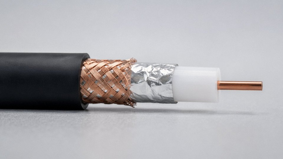
Working from the inside out: the center conductor is either solid or stranded copper, and that choice is not trivial. Solid conductors exhibit lower DC resistance and slightly better high-frequency performance due to reduced strand-to-strand capacitance variation, making them the standard choice for fixed broadcast and CATV installations. Stranded centers appear in cables that must survive repeated flexing — patch leads, OB van interconnects — though they come with a modest attenuation penalty at GHz-range frequencies.
The dielectric is where propagation velocity and attenuation are largely set. Solid polyethylene (PE) gives a velocity of propagation (VoP) of roughly 66% the speed of light. Foam PE — a cellular structure that replaces some dielectric mass with air — pushes VoP into the 78–85% range and cuts dielectric loss meaningfully; this is why LMR-400 and modern CATV drop cables use it. PTFE (polytetrafluoroethylene) dielectric is a different animal entirely: VoP around 69–71%, but it handles continuous temperatures up to roughly 200°C and performs across a much wider frequency range without the dielectric absorption artifacts that afflict PE above a few GHz. For microwave instrumentation or avionics-adjacent applications, PTFE is the standard. It also costs noticeably more — a relevant fact when procurement is specifying hundreds of meters.
The shield layer determines electromagnetic shielding effectiveness, and the common choice is foil plus braid. Foil (typically aluminum-polyester laminate, sometimes with a drain wire) provides continuous coverage and handles high-frequency interference well. A braided copper overscreen adds mechanical strength and improves low-frequency shielding; braid coverage of 95%+ is worth specifying explicitly, because 85% braid is a real thing that gets shipped when the PO doesn’t state otherwise. For CCTV in electrically noisy industrial environments — think a plant floor with variable-frequency drives nearby — shielding effectiveness of ≥85 dB is a reasonable minimum. Precision instrumentation sometimes goes to triaxial construction, adding a second isolated shield that serves as a driven guard conductor, which suppresses leakage currents in measurements below a few nanoamps.
Characteristic Impedance: Where 50 Ω and 75 Ω Come From
The governing relationship is:
Z₀ = (138 / √εᵣ) × log(D/d)
where D is the inner diameter of the outer conductor, d is the outer diameter of the center conductor, and εᵣ is the relative permittivity of the dielectric. This shows that impedance is fundamentally geometric — you can’t fix a mismatch with connector choice or termination technique after the cable is made.
Fifty ohms is the historical compromise point that balances power handling and attenuation for transmission and RF work. It dominates in RF test equipment, antenna feed lines, 5G base station jumpers, and military communications. Seventy-five ohms is the minimum-attenuation sweet spot for coaxial geometry in standard PE dielectrics — at fixed diameter, attenuation is lowest around 77 Ω, close enough that 75 Ω became the CATV and broadcast standard decades ago and stayed there. Mixing them is a classic installation error: a 75 Ω source driving a 50 Ω cable produces a reflection coefficient of about 0.2, adding return loss roughly in the 14 dB range — audible in audio and visible as picture artifacts in analog video.
Key Metrics to Pull from the Data Sheet
Procurement managers should request these explicitly, not assume:
| Parameter | Typical Range | Depends On |
|---|---|---|
| Attenuation at 1 GHz | ~18 dB/100 m (RG-6) to ~7 dB/100 m (LMR-400) | Dielectric type, conductor diameter, frequency |
| Velocity of propagation | 66–85% speed of light | Dielectric material and foam density |
| Shielding effectiveness | 60–100+ dB | Braid coverage %, foil integrity, connector quality |
| Min. bend radius (fixed) | ~10× outer diameter | Jacket stiffness, conductor diameter |
RG-58 at 50 Ω is a workhorse for lab instrument interconnects and short antenna runs but loses around 28–33 dB/100 m at 1 GHz — fine for a 2-meter patch cable, problematic for a 30-meter antenna feed. RG-213 handles higher RF power in the same 50 Ω family with a larger conductor and lower loss per unit length. For long outdoor antenna runs in cellular or broadcast infrastructure, LMR-400 equivalents with foam PE and 95%+ braid are the practical choice; the attenuation difference over a 40-meter run between RG-58 and LMR-400 at 900 MHz is substantial enough to affect link budget calculations in a way that matters.
Installation Realities
Connector termination is where coaxial performance often dies on the bench. A center pin crimped 0.3 mm off-axis, or a braid folded rather than properly trimmed, creates a localized impedance discontinuity visible as a return loss spike on a VNA. In a CCTV installation that uses passive video baluns or long runs to a DVR, that spike manifests as image ghosting. The fix after installation is usually cutting back the run and reterminating — avoidable with a go/no-go test at incoming inspection.
Outdoor aerial runs need UV-stabilized jacket compound and a defined temperature range on the data sheet, not just “suitable for outdoor use.” In environments that swing between -30°C winters and +60°C roof surface temperatures in summer, a standard PVC jacket becomes brittle or tacky in ways that accelerate jacket cracking, which lets moisture into the braid — and wet braid attenuation climbs noticeably within months.
Shielding effectiveness of coaxial cable depends on both the physical shield construction and the quality of connector termination, not cable construction alone.True
Even a cable rated for 90 dB shielding effectiveness will perform significantly worse if connectors are improperly terminated, because impedance discontinuities and gaps in the shield at the connector interface allow signal ingress and egress.
Jinda manufactures RG-series and equivalent coaxial cables with foam PE and solid PE dielectric options, foil-plus-braid dual-shield construction across standard braid coverage grades, and PTFE dielectric variants for elevated-temperature or wide-frequency applications. Custom outer jacket compounds — including low-smoke zero-halogen formulations and UV-stabilized polyethylene for direct burial or aerial installation — are available where the standard catalog doesn’t cover the operating environment.
Type 4 — Twisted-Pair Wire: Category Ratings, Crosstalk Suppression, and Data Network Cabling
Twisted-pair is the backbone of structured cabling — every office LAN, industrial Ethernet segment, and building automation network you’ve walked past almost certainly runs on it. The fundamental trick is elegant: two conductors carrying equal but opposite signals, twisted together, so any external electromagnetic noise couples into both wires simultaneously and cancels at the receiver. This is differential signaling, and the twist is what makes it work at scale without requiring heavy shielding on every run.
How the Twist Rate Actually Suppresses Interference
The key detail most installation guides skip is that every pair in a multi-pair cable — the typical Cat6 cable has four pairs — intentionally uses a different twist pitch. One pair might twist every 12 mm, the next every 14 mm, the next every 16 mm, and so on. This offset prevents the pairs from running parallel for any meaningful length, which is what drives alien crosstalk (ANEXT): the noise one pair induces into an adjacent pair in a neighboring cable or the same bundle. If all pairs twisted at the same rate, you’d get periodic alignment between them and NEXT performance would collapse at higher frequencies. It’s a small manufacturing detail that has real consequences — skimping on pitch differentiation shows up clearly in certification test results above 250 MHz.
Shielding Taxonomy: UTP, FTP, S/FTP, and What Each Actually Means
The ISO/IEC 11801 nomenclature follows a consistent pattern (overall shield/pair shield), but it gets conflated in the field constantly.
UTP (unshielded twisted pair) — no shielding at all, relies entirely on the twist. Suitable for Cat5e and Cat6 in clean office environments.
F/UTP (foil overall, unshielded pairs) — a single overall aluminum foil. Standard for Cat6A in moderate EMI environments; what most people call “FTP” loosely.
S/FTP (braid overall + individual foil per pair) — this is the full treatment, required for Cat7 and Cat8. The individual foil per pair controls inter-pair crosstalk independently; the braid handles external ingress. Heavier, stiffer, more expensive to terminate correctly.
SF/UTP — braid plus foil overall but no per-pair shielding; less common, used in some European installations for Cat6A where flexibility matters more than ultimate NEXT performance.
Category Performance — What the Numbers Mean in Practice
| Category | Bandwidth | Max Speed | Typical Channel Length | Shield Type | NEXT Loss (worst case) |
|---|---|---|---|---|---|
| Cat5e | 100 MHz | 1 Gbps | 100 m | UTP | ≥35 dB at 100 MHz |
| Cat6 | 250 MHz | 10 Gbps | 55 m | UTP or F/UTP | ≥44 dB at 250 MHz |
| Cat6A | 500 MHz | 10 Gbps | 100 m | F/UTP or S/FTP | ≥47 dB at 500 MHz |
| Cat7 | 600 MHz | 10 Gbps+ | 100 m | S/FTP | ≥65 dB at 600 MHz |
| Cat8 | 2,000 MHz | 25/40 Gbps | 30 m | S/FTP | ≥67 dB at 2,000 MHz |
Cat8 is essentially a data center product — top-of-rack switch connections, 30 m max, not a general building cable. Don’t let vendors quote it for horizontal runs.
Cat6A S/FTP is the minimum recommended cable type for IEEE 802.3bt (90 W PoE) installationsTrue
IEEE 802.3bt Type 4 (90 W) drives significant DC current through all four pairs simultaneously, raising conductor temperature. Cat6A's larger conductor cross-section and tighter DC resistance unbalance tolerance (≤2% within a pair per TIA-568-C.2) both reduce heat buildup and ensure balanced power delivery. Cat5e and Cat6 are not prohibited outright but create thermal margin problems in bundled runs.
Industrial Ethernet: Same Category, Different Jacket
Standard Cat6A designed for office plenum installations will fail within months in a machine tool environment. The upgrades matter: PUR (polyurethane) or LSZH jackets instead of PVC, an overall tinned copper braid, and oil/UV/crush resistance built to IEC 61156-5. These Industrial Ethernet variants carry the same electrical Category rating — 500 MHz, 10 Gbps — but the mechanical and chemical specs are entirely different. On a welding cell or a press line with hydraulic fluid mist in the air, jacket selection is not a secondary spec.
Termination: Where Cat6A Performance Goes to Die
The ANSI/TIA-568-C.2 maximum channel length of 100 m is well-known. Less observed is the requirement to maintain pair twist within the last 13 mm at every termination point — jack, patch panel, or field-terminated plug. Untwisting more than that to make punchdown easier degrades NEXT measurably at 500 MHz, and a properly calibrated Fluke DSX or equivalent certification tester will flag it. IDC (insulation displacement) punchdowns should use the correct 110-style impact tool set to the cable’s gauge; under-driven connections create intermittent failures under vibration. If your building contractor is terminating Cat6A with a flat-blade screwdriver and visual judgment, budget for re-certification.
Type 5 — Shielded Wire: EMI/RFI Protection Strategies for Industrial Control and Automation
Before getting into construction details, it’s worth being precise about what “shielded wire” means in this context. Coaxial cable has a shield. Shielded twisted pair has a shield. But neither of those is what plant electricians and controls engineers typically mean when they write “shielded cable” on a BOM. Here, shielded wire refers specifically to single-conductor or multi-conductor control and instrumentation cables — the kind covered by IEC 60502 and UL 2464 — where an overall EMI barrier wraps a bundle of signal or control conductors. It’s the cable running from your PLC analog input card to a field transmitter, or from a VFD to its motor. The shield is not the signal path. It’s a barrier.
Shield Construction and What It Actually Does at Frequency
Three constructions dominate industrial practice, and choosing the wrong one for the frequency range in question is a recurring source of commissioning headaches.
Aluminum-polyester (mylar) foil with drain wire provides 98–100% optical coverage and is the lightest, cheapest option. It works well as a static shield on low-frequency analog loops — 4–20 mA, thermocouple, RTD — where the primary threat is capacitive coupling from adjacent power cables. Above roughly 1–2 MHz its transfer impedance climbs steeply, so don’t specify it for anything faster.
Tinned copper braid runs 85–98% optical coverage depending on braid angle and wire count. It handles mechanical flexing far better than foil, which cracks after repeated bending (a real problem on cable carriers and robot tow chains). Braid’s bigger advantage is electrical: superior transfer impedance performance above 10 MHz, which matters for Profibus, EtherNet/IP field segments, or any cable near a VFD.
Foil-plus-braid combination covers the widest frequency range and is essentially mandatory for VFD output cables, per the guidance in IEEE 1100. The foil handles the lower-frequency capacitive coupling; the braid handles the high-frequency conducted emissions riding on the PWM waveform. It’s heavier and costs more — expect a price premium of roughly 25–45% over braid-only construction, depending on conductor count and insulation grade — but in a VFD installation you’re not making this choice twice if you get it right the first time.
Grounding: Where Most Installations Go Wrong
Single-point grounding at the control panel end only — shield floating at the field device — is correct for low-frequency analog signal cables. It prevents ground loops, which is the dominant noise mechanism at 50/60 Hz and below. Ground both ends of a thermocouple extension cable and you may inject exactly the interference you were trying to block.
Reverse this for high-frequency applications. VFD cables and high-speed digital fieldbus runs need both ends bonded to a low-impedance ground, giving HF noise currents a return path rather than forcing them to radiate. A 360-degree EMC cable gland, not a pigtail, is the right termination method at each end. Pigtails add inductance and largely defeat the shield above a few hundred kHz. In practice, pigtails are still common — installers use what’s on the shelf — and the resulting EMI complaints show up weeks later as spurious VFD trips or erratic analog readings.
VFD Cable: Not Just a Power Cable
VFD output cables carry PWM waveforms at switching frequencies typically between 2 kHz and 16 kHz, plus the associated reflected voltage spikes that can reach up to twice the DC bus voltage at the motor terminals. Standard THHN or PVC-insulated power cable fails here for two reasons: the insulation degrades under partial discharge caused by those voltage spikes, and there’s no provision for a low-impedance HF shield return path.
Proper VFD cable construction requires symmetrical three-phase conductor arrangement (minimizes unbalanced capacitive coupling), an overall tinned copper braid at ≥85% optical coverage, dedicated green/yellow ground conductors, and insulation rated 600 V or 1000 V with partial-discharge-resistant XLPE or EPR. Run lengths matter too — beyond roughly 50–150 meters (depending on drive manufacturer and switching frequency), reflected voltage overshoot can exceed motor insulation ratings even with compliant cable, and a load reactor or output filter may be necessary.
Reversing shield grounding practices — grounding both ends of an analog signal cable or single-end-grounding a VFD cable — is one of the most common causes of unexplained analog drift and nuisance VFD trips in new automation installations.True
Low-frequency analog shields grounded at both ends create ground loops that inject 50/60 Hz common-mode noise directly into the signal. VFD cables with shields grounded at only one end cannot provide the low-impedance HF return path needed to contain PWM-related emissions, allowing conducted interference to radiate or couple into adjacent control circuits.
Instrumentation Cable Standards and Mechanical Protection
ISA-5.1 color coding applies to thermocouple and RTD extension cables; IEC 60332 flame-retardant ratings are usually specified by the site’s electrical area classification requirements. In petrochemical or offshore environments, flame-retardant isn’t optional — it’s contractual.
Armored instrumentation cable — SWA (steel wire armor) or AWA (aluminum wire armor) per IEC 60502-1 — is worth the cost wherever cable trays see forklift traffic, heavy foot traffic, or known rodent pressure. The weight penalty is real, but a crushed instrument cable in a production environment costs more in troubleshooting time than the armor ever does.
Jinda Shielded Cable Product Scope
Jinda manufactures multi-pair instrumentation cables from 2-pair up to 40-pair configurations, VFD-rated power cables, and PLC I/O cables with both individual-pair and overall shields. Insulation options cover PVC, LSZH, and XLPE depending on installation environment and flame/smoke requirements. For offshore oil and gas projects, custom constructions certified to DNV GL or ABS marine standards are available — a meaningful differentiator when EPC contractors need a single qualified cable supplier across both topside instrumentation and power distribution runs.
Type 6 — Specialty and High-Performance Wire: Extreme Environments and Emerging Applications
The five wire types covered earlier handle the majority of installations, but a meaningful slice of today’s projects — offshore wind farms, EV charging infrastructure, semiconductor fabs, high-frequency power converters — demand something the standard catalog simply doesn’t cover. These specialty categories are also where specification errors are most expensive, because the operating conditions leave almost no margin.
High-Temperature Wire: Silicone, PTFE, and the Thermal Cycling Problem
Silicone-insulated wire rated to 200°C continuous (UL 3132, IEC 60245-4) is the workhouse choice for furnace wiring, industrial ovens, and motor lead connections in hot environments. PTFE and FEP insulations push that ceiling to 260°C (UL 1180, MIL-W-16878), which is why they dominate aerospace harnesses and semiconductor fab equipment — plasma etchers and CVD chambers run internal temperatures that would destroy any organic insulation inside of a few hundred hours.
The spec most engineers underweight is voltage withstand under thermal cycling, not the static temperature rating. Insulation that passes a 1,500 V dielectric test at room temperature can develop micro-cracks after 500–1,000 heat cycles between ambient and operating temperature, dropping withstand to dangerous levels. Always ask for thermal-cycle dielectric data, not just the nameplate rating.
Submersible and Submarine Cable: Water Blocking Is Non-Negotiable
Continuous water immersion per IEC 60502-4 and ICEA S-75-381 requires a construction philosophy that’s fundamentally different from dry-location cable. Longitudinal water-blocking — either swellable tape around the conductor bundles or flooding compound filling the interstices — prevents water from migrating along the cable length if the outer jacket is breached. A lead sheath offers the best water barrier but adds weight and cost; PE/HDPE sheaths are more common for offshore wind and deep-well pump drops to depths exceeding 1,000 m, where hydrostatic pressure compounds the ingress risk. Wire armor or flat armor handles crush and tensile loads during deployment and retrieval. Skip any of these layers to save money and you’re usually looking at a full cable replacement within two to three years in a live subsea installation — not a repair.
Solar PV Wire: DC Arc Faults Are Not Like AC Faults
TÜV-approved EN 50618 and UL 4703 photovoltaic wire uses XLPE or HEPR insulation rated 90°C wet / 120°C dry, in 600 V or 1,000 V DC versions, with a UV-stabilized black jacket and double insulation construction. The IEC 61730 system voltage compliance requirement is straightforward enough. What catches people off guard is the DC arc fault behavior. Unlike AC, where a fault arc self-extinguishes at current zero, a DC arc sustains itself until the conductor burns through or the circuit is broken. That makes insulation dielectric strength a genuine safety-critical spec, not just a box to check.
EV Charging Cable: Flexibility and Temperature Range Together
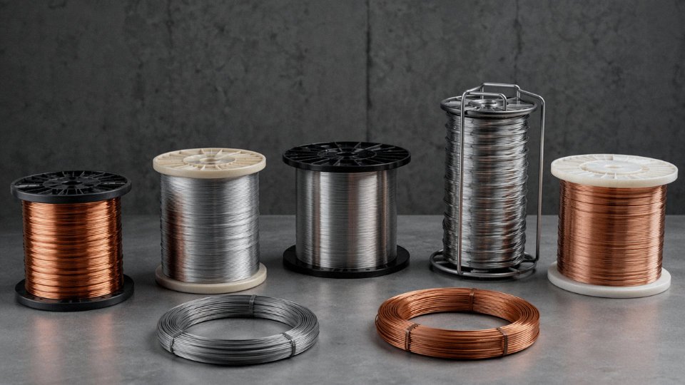
IEC 62893-3 and UL 2251 compliant EV charging cables run 32 A to 200 A at up to 1,000 V DC for Level 3 DC fast charging. The conductor must be Class 6 finely stranded copper to survive the repeated coiling and dragging that a public charging station sees — roughly 30,000 to 50,000 flex cycles over a service life, depending on installation type. TPU or PUR jacket handles pavement abrasion and chemical exposure from road salt and hydraulic fluids. Pilot and proximity signal conductors are integrated into the same assembly, which means the cable cross-section is more complex than it looks from the outside. Operating range of −40°C to +90°C is mandatory for outdoor installations in climates from northern Scandinavia to desert Southwest — a jacket compound optimized for one end of that range often compromises the other.
Litz Wire: Skin Effect Has a Measurable Cost
Above roughly 10 kHz, conventional stranded wire loses efficiency fast because current crowds to the conductor surface, effectively reducing the usable cross-section. Litz wire addresses this by using individually insulated strands that are transposed (twisted in a specific geometric pattern) so each strand occupies every radial position equally over the cable length. Used in wireless power transfer coils, high-frequency transformers, and GaN/SiC power converter inductors, Litz wire is specified by strand count, individual strand diameter, and build — single, triple, or quadruple insulation layers depending on the voltage between turns. Getting the strand diameter wrong for the operating frequency costs 3–8% in converter efficiency in practice; at megawatt scale, that’s real money.
Data Center Twinax and the 800G Inflection Point
Direct attach copper (DAC) twinax assemblies handle 400G and 800G short-reach interconnects up to about 5 m. They’re lower cost and lower latency than active optical cables at those distances. But above 3 m at 800G speeds, the power-per-bit economics shift decisively toward fiber — the signal conditioning electronics needed to push copper that far start consuming more power than the optical transceiver alternative. Large hyperscale operators are already setting their internal standards accordingly. If you’re specifying infrastructure that will scale to 800G within its service life, that crossover point is worth building into the cable plant design now rather than retrofitting later.
PTFE-insulated wire rated to 260°C is required for most semiconductor fab equipment wiringTrue
Plasma etch, CVD, and similar semiconductor process equipment regularly exposes internal wiring to sustained temperatures well above what silicone insulation can handle continuously. UL 1180 and MIL-W-16878 PTFE wire is the standard solution for these applications precisely because of its 260°C continuous rating and chemical inertness.
Side-by-Side Comparison: Matching Wire Type to Voltage, Environment, and Flex Cycle Requirements
Getting the right wire type on paper is one thing. Watching the wrong choice fail six months into a production run — because someone grabbed the cheapest stranded PVC they could find for a VFD cabinet — is another. This section consolidates the key selection parameters into scannable references you can use during spec review, procurement negotiation, or a field audit.
Master Comparison Table
| Wire Type | Typical Conductor | Key IEC/UL Reference | Voltage Range | Temp Range | Shielding | Flex Class | Primary Domain |
|---|---|---|---|---|---|---|---|
| Solid | Cu or Al | UL 83 / IEC 60228 Cl.1 | 300 V–35 kV+ | −20 °C to +90 °C (PVC) | Rarely | Static only | Building wiring, overhead distribution |
| Stranded | Cu (tinned optional) | UL 44 / IEC 60228 Cl.2–6 | 300 V–1 kV typical | −30 °C to +105 °C | Optional | Cl.2–Cl.6 | Panel wiring, OEM machine wiring, cable trays |
| Coaxial | Cu or CCS center | MIL-C-17 / IEC 61196 | Signal-level to ~3 kV (RG-8) | −40 °C to +85 °C | Integral (braid + foil) | Low–moderate | RF, CCTV, broadcast, instrumentation |
| Twisted-pair | Cu (bare or tinned) | TIA-568 / ISO 11801 / IEC 61156 | ≤100 V signal | 0 °C to +60 °C (Cat5e–Cat8) | UTP / FTP / STP | Moderate | Ethernet, fieldbus, telecom |
| Shielded | Cu, multi-conductor | UL 2464 / IEC 60332 | 300 V–600 V typical | −40 °C to +105 °C | Foil, braid, or combined | Cl.2–Cl.5 | PLC I/O, VFD, process control |
| Specialty/HT | Cu, Ni, or Al alloy | IEC 60092 / UNE, TÜV, DNV GL | 0.6/1 kV to 66 kV+ | −60 °C to +250 °C | Type-dependent | Application-specific | Marine, EV, solar PV, high-temp industrial |
Temperature ranges shift considerably based on insulation material — silicone versus XLPE versus standard PVC are not interchangeable, even at the same voltage rating.
Environmental Suitability Matrix
| Wire Type | Indoor Dry | Indoor Wet | Outdoor UV | Direct Burial | Submerged | High-Vibration | High-EMI Automation |
|---|---|---|---|---|---|---|---|
| Solid | Yes | Conditional¹ | Conditional² | Conditional³ | No | No | Conditional |
| Stranded | Yes | Conditional¹ | Conditional² | Conditional³ | No | Yes | Conditional |
| Coaxial | Yes | Conditional¹ | Conditional² | No | No | Conditional | Yes |
| Twisted-pair | Yes | Conditional¹ | No | No | No | Conditional | Yes (STP/FTP) |
| Shielded | Yes | Conditional¹ | Conditional² | Conditional³ | No | Yes | Yes |
| Specialty | Yes | Yes (type-dep.) | Yes (type-dep.) | Yes (type-dep.) | Yes (submarine) | Yes | Yes (type-dep.) |
¹ Requires moisture-rated jacket (e.g., LSZH, TPE, or PE) and appropriate IP-rated terminations. Standard PVC absorbs moisture over time in wet locations — slowly, but it does.
² UV-stabilized jacket required; standard black PE or UV-rated PVC only. Clear or light-colored PVC jackets degrade noticeably within 12–18 months of outdoor sun exposure in high-UV climates.
³ Direct burial typically requires PE jacket plus conduit, or a specifically rated direct-burial compound. “Outdoor-rated” does not automatically mean burial-rated.
Flex Cycle Decision Guide
Three categories cover most real applications:
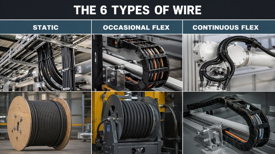
Static/fixed installation — solid wire (IEC 60228 Class 1) or Class 2 stranded. No intended movement after installation. Rated for essentially unlimited service life in stable thermal and mechanical conditions. Routing in conduit, trunking, or embedded in structures.
Occasional flex — Class 5 fine-stranded wire. Covers applications moved during maintenance, repositioning, or setup changes, roughly up to around 50,000–100,000 flex cycles depending on bend radius and conductor cross-section. Machine tool doors, hinged panels, service loops.
Continuous dynamic flex — Class 6 or Litz construction. IEC 60228 Class 6 test protocols reference ≥10 million cycles at a 4× OD bend radius as a baseline acceptance criterion, though real-world cable track ratings from reputable suppliers often quote 5–20 million cycles depending on speed, acceleration profile, and ambient temperature. Robotic arms, drag chains, automated guided vehicles. Using Class 2 cable here is the single most common wiring failure I’ve seen in cable track installations — the conductors fatigue-fracture, intermittent faults appear, and the root cause takes weeks to diagnose.
Relative Cost Index
Base index: standard stranded copper Class 2, PVC-insulated, 2.5 mm² = 100.
| Cable Type | Approximate Cost Multiplier | Key Driver |
|---|---|---|
| Tinned stranded, same spec | 1.1–1.3× | Tin coating process, material cost |
| Shielded instrument cable (foil + drain) | 1.5–2× | Shield materials, tighter tolerances |
| VFD-rated cable (shielded, symmetrical) | 2–3× | Symmetrical ground conductors, robust jacket |
| Silicone HT wire (rated ≥180 °C) | 3–5× | Silicone compound cost, extrusion complexity |
| Submarine/umbilical cable | 10–20× | Armor, pressure testing, certification stack |
These are rough procurement-level estimates. Actual pricing depends on copper spot price (LME), order volume, delivery lead time, and whether the project requires third-party certification testing on the specific reel lot.
Certification and Compliance Checklist
Not every wire type needs every mark. Here’s where the typical requirements land:
| Certification | Solid | Stranded | Coaxial | Twisted-pair | Shielded | Specialty |
|---|---|---|---|---|---|---|
| UL Listing (US) | ✓ | ✓ | ✓ | ✓ | ✓ | ✓ (type-dep.) |
| CE / CENELEC (EU) | ✓ | ✓ | ✓ | ✓ | ✓ | ✓ |
| CCC (China domestic) | ✓ | ✓ | — | ✓ | ✓ | Conditional |
| CSA (Canada) | ✓ | ✓ | Conditional | Conditional | ✓ | Conditional |
| DNV GL / ABS / BV (marine) | — | Conditional | — | — | Conditional | ✓ |
| TÜV (solar PV) | — | — | — | — | — | ✓ (PV wire) |
| IEC 60332 (flame propagation) | ✓ | ✓ | ✓ | ✓ | ✓ | ✓ |
| IEC 61034 (smoke density) | Conditional | Conditional | Conditional | Conditional | Conditional | ✓ (LSZH) |
| RoHS / REACH | ✓ | ✓ | ✓ | ✓ | ✓ | ✓ |
IEC 60332-3 flame test requirements apply to cables installed in bundles, not just single-cable installations, and failing to specify bundle-rated cables in multi-cable trays is a genuine fire-spread risk.True
IEC 60332-3 specifically addresses flame propagation in grouped/bunched cable installations. Single-cable IEC 60332-1 compliance does not guarantee compliance when cables are run in high-fill cable trays, which is why the distinction matters in tray design and procurement specifications.
Red-Flag Misapplication List
Eight failures that show up repeatedly in field audits:
- UTP Cat5e in a VFD cabinet without shielding. Common in budget retrofits. Result: packet errors, drive faults, nuisance trips. Fix: replace with STP Cat6A or dedicated shielded instrument cable, single-point ground at panel end.
- Solid wire in a flex track or cable chain. Conductor work-hardens and fractures at the first tight bend, usually within weeks. Fix: minimum Class 5 stranded; Class 6 for continuous motion.
Standard PVC-jacketed cable in direct burial without conduit. Plasticizer migration, rodent damage, moisture ingress within 2–5 years in most soil conditions. Fix: PE-jacketed direct-burial rated cable, or conduit with standard cable.
Unshielded cable on analog 4–20 mA loops near variable-speed drives. Signal noise reads as process variable drift. Operators compensate manually; process runs inefficiently for months before anyone traces the source. Fix: shielded twisted-pair, foil minimum, grounded at one end.
Using coaxial RG-59 for long CCTV runs over 200–250 m. Attenuation at 5–6 MHz rolls off picture quality noticeably. Fix: RG-6 minimum; active balun or fiber for runs beyond 300 m.
Aluminum conductor wire terminated in copper-only lugs without anti-oxidant compound. Galvanic corrosion raises contact resistance, overheats terminations. Fix: bi-metal lugs rated for Al/Cu, plus no-ox compound at every termination.
Standard silicone wire routed through a cable drag chain at high cycle rates. Silicone insulation has excellent thermal properties but poor abrasion resistance — jacket wears through against chain links within months. Fix: specify drag-chain-rated TPE or PUR jacket for mechanical protection, even if the conductor runs hot.
Specifying a 300/500 V rated cable on a 690 V nominal system because the actual measured phase-to-ground voltage “usually” stays below the limit. Insulation stress accumulates; partial discharge develops over 12–24 months; insulation failure follows. Fix: 0.6/1 kV rating minimum for 690 V systems, no exceptions.
How to Write a Wire Procurement Specification That Prevents Costly Substitutions
A purchase order that says “supply cable per IEC 60502-1” is not a specification. It’s an invitation for a supplier to ship the cheapest product that clears the standard’s minimum thresholds — and those minimums can be surprisingly low. Getting this right before the order goes out saves far more than it costs in engineering time.
The Specification Hierarchy You Must Enforce
Project specification overrides manufacturer datasheet overrides generic standard. Write that down somewhere visible. The failure mode I see most often is a buyer referencing only a standard number, then discovering mid-installation that the supplied cable meets the letter of that standard while missing every project-specific requirement — wrong jacket compound for a wet duct, conductor resistance at the high end of the permitted band, insulation thickness at the minimum tolerance. All technically compliant. All wrong for the job.
Your project spec should explicitly state that it supersedes conflicting datasheet claims, and that any deviation requires written approval. That sentence alone eliminates most of the gray area suppliers exploit.
The 10 Mandatory Line Items
Every wire specification should lock down these items. Leave any one undefined and you’ve handed a supplier a substitution path.
- Conductor material and purity — specify ETP copper per ASTM B3 or IEC 60028, not just “copper.” Electrolytic-tough-pitch copper runs roughly 100–101% IACS conductivity; lower-grade rod can drop to 97–98% IACS, which matters at scale when you’re calculating voltage drop over a 500 m run.
- Conductor class per IEC 60228 — Class 1 (solid), Class 2 (stranded), Class 5 (flexible). Don’t let this float.
- Insulation compound and minimum thickness — XLPE vs. PVC vs. EPR behave very differently above 70°C. State the compound family and the minimum thickness in millimeters, not just a voltage class.
- Shield type and minimum optical coverage — for braided shields, 85% optical coverage is common; 90–95% is worth specifying for VFD cables or anything in a high-EMI environment. Foil-only shields should state whether drain wire is required and its minimum cross-section.
- Jacket compound and minimum thickness — PVC, LSZH, PUR, or CPE. For outdoor runs, require carbon black content ≥ 2% by weight for UV resistance.
- Voltage rating (Uo/U) — state it explicitly: 0.6/1 kV, 1.8/3 kV, whatever the design requires. Never leave it implied by the standard reference.
- Temperature rating — both installation temperature (typically −15°C to −5°C minimum for most PVC jackets) and continuous service temperature.
- Flame and smoke test standard with pass criteria — IEC 60332-3-24 Category C for bunched cable, IEC 61034-2 minimum 60% light transmittance for LSZH. Specifying the test without the pass threshold is useless.
- Color code standard — IEC 60446, NEC, or project-specific. Surprisingly often omitted, and the resulting rework cost during termination is real.
- Drum length tolerance — ±0%/+5% is the industry default, meaning you may get slightly more than ordered but never less. If your installation schedule is tight or reel storage is limited, specify ±0 explicitly and expect a small price premium.
Third-Party Testing and FAT Requirements
Don’t accept pass/fail certificates. Require actual measured values — conductor DC resistance per IEC 60228 Table 1 (in Ω/km at 20°C), insulation resistance at 1 kV DC for 1 minute (minimums vary by insulation type; XLPE typically exceeds 1,000 MΩ·km, PVC may run 50–200 MΩ·km depending on compound), and high-voltage withstand per IEC 60502-1 Clause 17. Shield continuity should be a measured loop resistance, not a visual check.
Requiring actual measured test values — not just pass/fail stamps — on IEC 60228 resistance and IEC 60502-1 withstand certificates is standard practice for major international cable procurement.True
IEC 60502-1 and IEC 60228 both specify test methods with quantitative acceptance criteria; reputable manufacturers routinely issue drum-by-drum test certificates with measured values, and project specifications for infrastructure and industrial work routinely require this as a contract condition.
Factory acceptance testing adds cost — usually a modest inspection fee plus travel if you send a third-party auditor — but it catches problems before the cable is on a ship. In practice, specifying FAT in the contract also changes supplier behavior upstream, which is half the point.
Material Traceability
Require mill certificates for copper rod showing chemical composition and conductivity. For UV-resistant jackets, insulation compound certificates should confirm polymer grade and carbon black percentage. Shield tape or braid material certificates should state material grade and, for tinned copper braid, the tin coating weight. These documents need to travel with the shipment, not arrive six weeks later when the cable is already pulled in conduit.
Controlling “Or Equal” Substitutions
If you’ve approved a specific manufacturer, define equivalency in quantitative terms: same or superior IEC conductor class, same or larger cross-section, same insulation compound family, same or higher voltage and temperature rating, same certifications (UL, CE, or project-specific approvals). An undefined “or equal” clause gives procurement unlimited latitude, and budget pressure almost always wins that argument.
Incoming Inspection at the Reel
When cable arrives on site: check drum markings against the spec (manufacturer, standard, voltage, cross-section, length) — discrepancies here sometimes indicate the wrong product entirely. Measure conductor DC resistance with a calibrated micro-ohmmeter and compare against IEC 60228 Table 1 limits; a resistance 3–5% over limit on a large conductor often points to undersized stranding or off-spec copper. Perform a spark test at rated voltage on a sample length of insulation. Measure the overall diameter with a micrometer at three points along a cut end and check against the ±5% OD tolerance in your spec.
This whole process sounds like overhead. It isn’t. One drum of substituted cable pulled into an inaccessible cable tray costs more to remediate than the entire inspection program for a medium-sized project.
Frequently Asked Questions About Wire Types
What is the difference between a wire and a cable?
A wire is a single conductor — bare or insulated. A cable is two or more conductors, or a single conductor combined with a shield or armor, all assembled under a common jacket. IEC 60050-461 draws that line formally. In everyday plant-floor conversation, people say “wire” when they mean an insulated single conductor, which is close enough for most purposes. Where it matters is procurement: ordering “wire” when the spec calls for “cable” can mean receiving something that fails inspection or, worse, something that gets installed and fails in service.
Can I use stranded wire instead of solid wire in a junction box?
Yes, in most cases. Both NEC and IEC permit stranded conductors in junction boxes provided the termination hardware is rated for stranded conductors. The failure mode to watch: pushing stranded wire under a screw terminal designed only for solid wire. Individual strands can spread, a few end up outside the terminal, and you get a high-resistance joint that overheats. The fix is straightforward — crimp a ferrule onto the stranded end before terminating. It takes maybe 15 seconds with a decent Knipex or Weidmüller tool and prevents a nuisance fault that’s surprisingly hard to find once the panel is buttoned up.
What gauge wire do I need for a 20-amp circuit?
Per NEC Table 310.15(B)(16), 12 AWG copper THHN/THWN handles 20 A at 60°C. That’s the starting point, not the final answer. Run three or more current-carrying conductors in a conduit and you’re already derated — typically down to roughly 70–80% of the base ampacity depending on fill count. Ambient temperatures above 30°C add another derating layer; at 40°C that’s roughly a further 10–12% reduction for PVC-insulated conductors. In hot machine rooms or outdoor conduit runs in summer, what looked like adequate 12 AWG can actually be undersized for sustained load. When in doubt, move up a gauge.
Why does VFD cable cost more than standard power cable?
Several legitimate reasons. VFD cable needs a symmetrically arranged three-phase construction so the impedances balance; an unbalanced cable creates circulating currents on the shield. The shield itself has to provide at least 85% optical coverage — usually a combination braid and foil — to contain the high-frequency EMI that inverter switching generates. Insulation has to handle reflected voltage spikes that can reach roughly 1.5–2× the DC bus voltage depending on cable length and rise time. Add dedicated grounding conductors and you have significantly more material and more manufacturing steps than a standard power cable. The cost premium is real, typically 30–60% over comparable unshielded power cable depending on conductor size and shield construction, but it’s not padding — it’s what keeps the VFD drive from radiating noise into every sensor in the panel.
What is the maximum temperature rating available for industrial wire?
Standard PVC tops out around 70°C. XLPE gets you to 90°C wet, 105°C dry. Silicone rubber runs continuously to 180–200°C. PTFE handles 260°C continuous, and short-duration PTFE constructions rated to 300°C exist for specific aerospace and furnace applications. Beyond 300°C, you’re into ceramic-fiber insulated or mineral-insulated (MI) cable territory. MI cable is essentially indestructible thermally but rigid and expensive to terminate — not something you reach for unless the application genuinely demands it.
What does LSZH mean and when is it required?
LSZH — Low Smoke Zero Halogen — means the insulation and jacket compounds produce minimal smoke and release no halogenic acid gases when they burn. In a tunnel or a below-deck ship corridor, PVC burning produces hydrochloric acid gas that incapacitates people faster than the fire does. IEC 60332-3, NFPA 130, and most offshore platform standards require LSZH in exactly those confined-space environments. When specifying, call out IEC 61034-2 for smoke density (light transmittance ≥60%) and IEC 60754-1 for halogen acid gas content (≤0.5% HCl equivalent). Without those test references, “LSZH” on a data sheet is just a marketing claim.
How do I know if a manufacturer’s cable certifications are genuine?
Check the primary source, not the manufacturer’s brochure. UL listings are searchable by file number on UL Product iQ at iq.ul.com. CE Declarations of Conformity can be cross-referenced against the notified body’s public database. CCC certificates for the Chinese market are verifiable on the CNCA official portal. For marine and offshore cables, DNV, ABS, and Bureau Veritas each maintain online certificate finders where you can confirm type approval status by certificate number. A legitimate manufacturer has no hesitation providing those certificate numbers in writing.
Jinda provides verifiable certificate numbers for all listed product families upon request.True
Reputable manufacturers maintain active certification files with traceable numbers; Jinda's multi-market export history across 50+ countries requires maintaining current UL, CE, and CCC certifications.
What is the shelf life of wire and cable in storage?
Longer than most people assume, if storage conditions are controlled. PVC-insulated cable stored correctly — off UV exposure, away from ozone sources like motors or welders, in temperatures between roughly −10°C and +50°C, drums kept upright — is generally usable for up to 10 years per IEC 60502 guidance. XLPE-insulated cable in the same conditions can go 20 years or more. Before installing long-stored stock, physically inspect it: run your hands along the jacket looking for cracking or stiffness, check for oxidation on any exposed copper ends, and do a simple insulation resistance test before pulling it into conduit. Discovering degraded insulation after a 200-meter pull is an expensive lesson.
Partnering with Jinda for International Cable Supply: Capacity, Lead Times, and Quality Assurance
If you’ve worked through the six wire types above and you’re now building a cable schedule for a real project, the next question is practical: who actually manufactures to spec, ships reliably, and won’t substitute conductor cross-sections quietly when copper prices spike?
Manufacturing Scale and Product Breadth
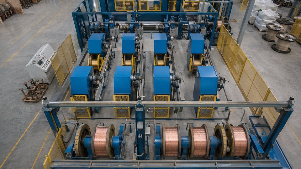
Jinda operates five production bases across China with a combined 470,000 m² of manufacturing floor space — roughly the footprint of 65 football pitches. That scale matters operationally, not just as a headline figure. It means solid and stranded power conductors, coaxial and data cables, shielded instrument cables, solar PV wire (TUV 2Pfg 1169-compliant and UL 4703), and EV charging cable can all ship on the same purchase order, from the same QA system, on the same documentation package. For EPC contractors running a substation build alongside a PV array and a building management system, single-source supply eliminates the coordination overhead that eats procurement hours on large projects.
International Supply Track Record
Products have shipped to customers in more than 50 countries — Southeast Asia, the Middle East, Africa, Europe, and the Americas. In practice, that geographic spread means Jinda’s export team has handled country-specific compliance documentation repeatedly, not theoretically. CE marking under the Low Voltage Directive, UL listing evidence, BS 6724 and BS 7211 references for UK and Commonwealth projects, AS/NZS 5000.1 for Australian buyers, and IEC 60502 as the baseline for most international tenders — the documentation team knows what each destination market’s customs and engineering approval process actually requires.
Certificates of Origin for GSP and other tariff preference programs, fumigated wooden reel packing (ISPM 15 compliance is standard, not an add-on), and bilingual material safety data sheets are included as standard on export orders. These aren’t small details — a missing fumigation certificate has held containers in Australian quarantine for weeks on more than a few projects across the industry.
Jinda's export packaging includes ISPM 15 fumigation certificates as standard on all container shipments.True
ISPM 15 is an international phytosanitary standard for wood packaging material used in international trade. Compliant fumigation certificates are a customs requirement in Australia, the US, the EU, and many other markets. Jinda states this is standard practice on export orders.
Quality Management and Testing
ISO 9001:2015 certification covers the full production and delivery cycle. The in-house laboratory runs conductor resistance, insulation resistance, high-voltage withstand (AC and DC), tensile and elongation, flame propagation, smoke density, and thermal aging — not outsourced, not selective. Mill certificates with actual measured values, not just “pass/fail” stamps, come as standard deliverables. Third-party witnessed factory acceptance testing (FAT) is available and is, honestly, worth requesting on any order above roughly USD 50,000 or where site commissioning failure would be costly.
Lead Times and Logistics
Common power and control cable sizes typically ship within 15–30 days from order confirmation. Custom constructions — unusual cross-sections, specialized insulation compounds, armored or individually shielded pairs, anything requiring a drawing approval cycle — run 30–60 days depending on raw material lead time and production scheduling. That range depends heavily on copper market conditions and whether the compound is stocked; it’s worth confirming at the RFQ stage rather than assuming.
Pre-Sales Technical Support
Application engineers will review cable schedules, flag mismatches between specified wire type and installation environment, and run IEC 60287-based ampacity calculations for your actual conduit fill and ambient temperature conditions — at no charge for qualified project inquiries. That service routinely catches undersized neutrals and oversized shielding specs before they become field problems.
Partnership Models
Four commercial structures are available: spot orders with minimum quantities by product family; blanket purchase orders with scheduled releases (the preferred model for EPC contractors on multiyear builds); private-label OEM supply where Jinda manufactures to your brand and specification; and consignment stocking programs for distributors in active markets. Contact Jinda’s international sales team with your project scope and annual volume estimate to get a supply proposal structured around your actual requirements.