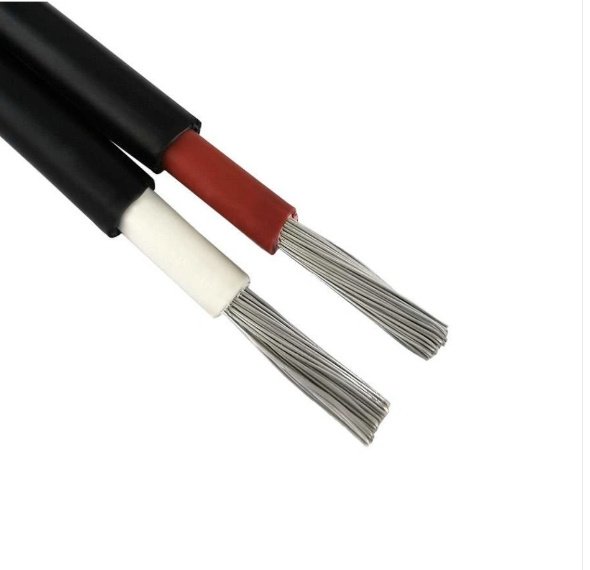
Miswire a ground conductor as a neutral and you’ll likely trip a breaker — best case. Worst case, you’re looking at a line-to-ground fault that takes out a motor drive, scorches a panel enclosure, and puts a maintenance crew on overtime for two shifts while a production line sits cold. Most wiring failures in industrial installations don’t trace back to bad hardware; they trace back to someone who wasn’t clear on what each conductor in the cable was actually supposed to do. That confusion costs real money, and it’s more common than any plant manager likes to admit.
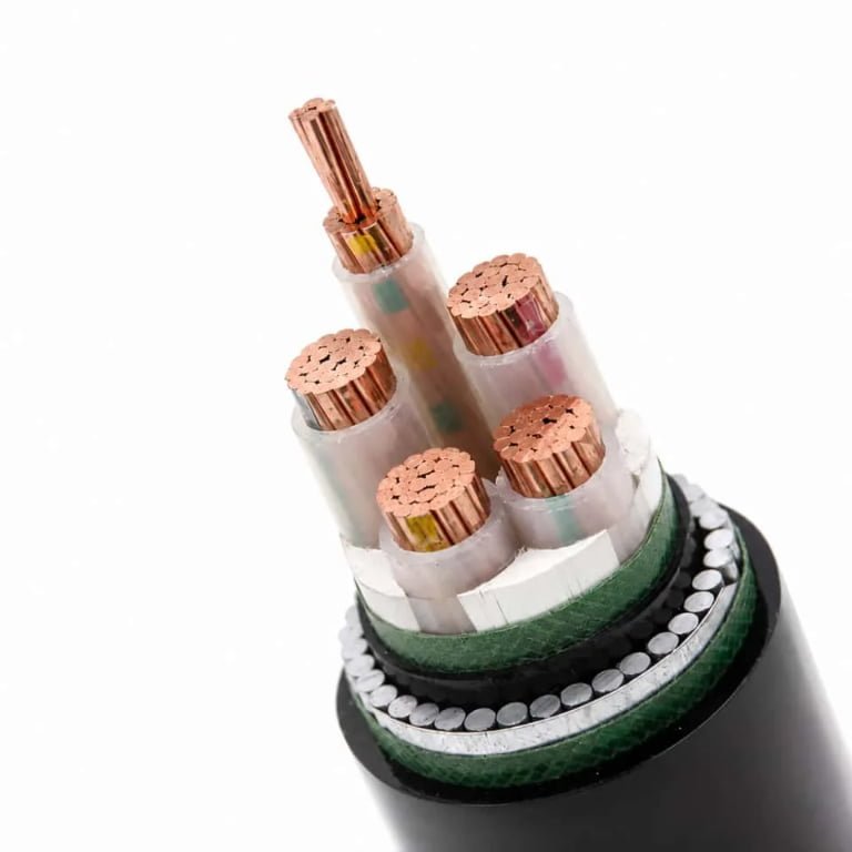
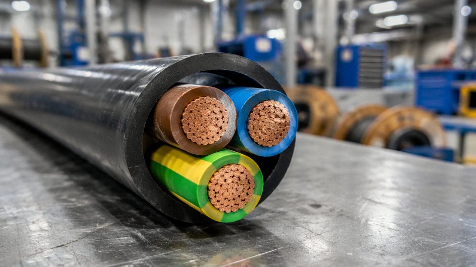
Every standard power cable contains three functional wire types: a live (phase) conductor that carries current to the load, a neutral conductor that returns current to the source and completes the circuit, and a protective earth (ground) conductor that provides a safe fault-current path. Each is distinguished by insulation color coding per regional standards (IEC, NEC, or BS 7671), conductor class, cross-section, and in some designs, construction material — copper or aluminum — depending on current rating, flexibility requirements, and installation conditions.
What makes this deceptively tricky in practice is that the physical construction of each conductor type can differ significantly inside the same cable jacket — a solid Class 1 conductor in one position, a finely stranded Class 5 in another — and those differences matter the moment you’re specifying insulation ratings, pulling cable through conduit at −10°C in January, or sourcing a replacement reel mid-project when your original vendor is two weeks out.
The Live (Phase) Wire: Current-Carrying Function, Conductor Physics, and Insulation Requirements
The live wire — called the phase conductor, hot wire, or line conductor depending on your regional standard — carries current from the source to the load at full system voltage relative to earth. That last part matters. During normal operation, touch it and you complete a circuit through your body to ground. Every other design decision about this conductor flows from that basic, unforgiving fact.
In single-phase systems you have one live conductor. In three-phase systems you have three: L1, L2, and L3, each displaced 120° from the others, each running at full line-to-earth voltage. A 400 V three-phase system in Europe means each live conductor sits at roughly 230 V to earth continuously. A 6/10 kV medium-voltage cable carries each phase conductor at 6 kV to earth. Ampacity and insulation thickness both scale with that voltage, not the phase-to-phase figure.
Conductor Material: Copper vs. Aluminum and Why It Isn’t Just a Cost Decision
Annealed copper is the global default for live conductors, and for good reason. Its resistivity of 1.72 × 10⁻⁸ Ω·m at 20°C means you can push more current through a given cross-section than almost any practical alternative. IEC 60228 Class 2 stranded copper — the most common construction in industrial and building cables — combines that conductivity with enough flexibility to survive installation bending cycles without work-hardening and cracking. Class 5 and Class 6 constructions take flexibility further, using fine-wire bundles for trailing cables, welding leads, and mobile equipment where the conductor flexes thousands of times over its service life.
Aluminum has a resistivity of 2.82 × 10⁻⁸ Ω·m, roughly 64% of copper’s conductivity by cross-section. To carry the same current you need a larger conductor — typically 1.5 to 1.6 times the copper cross-section, depending on the specific installation and derating conditions. That sounds like a penalty, but in large distribution cables (185 mm² and above, roughly) and overhead transmission lines, the weight savings dominate the engineering economics. A 240 mm² aluminum conductor weighs less than half its copper equivalent per meter. For long aerial runs, that difference in sag tension, pole loading, and installed cost is decisive.
What aluminum cannot do well is terminate reliably without proper compression lugs and anti-oxidant compound. Many plant electricians have seen aluminum connections fail years after installation because someone used the wrong lug or skipped the compound. That failure mode is worth keeping in mind during specification.
Ampacity: What Actually Determines How Much Current the Live Wire Can Carry
Cross-section is only the starting point. IEC 60364-5-52 and NEC Table 310.15 both apply correction factors for ambient temperature, installation method (conduit, tray, direct burial, free air), and cable grouping. Bundle six current-carrying conductors together in a tray and your derating factor might drop to 0.57 or lower, depending on the standard and configuration. A 16 mm² copper conductor rated for 76 A in free air at 30°C ambient might be derated to around 43–50 A in a fully loaded multi-cable tray in a 40°C environment. Getting this wrong doesn’t trip a breaker immediately — it accelerates insulation aging over months or years until you have an unplanned outage or worse.
Insulation: Matching the Material to the Voltage Class and Operating Temperature
PVC insulation on a live conductor is typically rated to 70°C continuous conductor temperature. It handles the 0.6/1 kV voltage class well and is cost-effective for general building and industrial wiring. The dielectric strength of PVC runs 10–20 kV/mm depending on compound formulation and temperature — adequate for low-voltage applications, but thin margins at medium voltage.
XLPE becomes the preferred choice from roughly 3.6/6 kV upward and anywhere continuous operating temperature pushes toward 90°C. Its cross-linked molecular structure resists thermal deformation under load, and its dielectric strength can reach the upper end of that 20 kV/mm range in high-grade formulations. Short-circuit withstand is rated to 250°C, which gives meaningful headroom during fault events that would destroy PVC insulation.
EPR (ethylene propylene rubber) occupies a different niche — flexible cables, mining equipment, offshore installations, and any application where mechanical flexing and chemical resistance matter more than pure cost. Its continuous rating also sits at 90°C. In practice, EPR appears most often on live conductors in mobile and trailing cable constructions where XLPE’s relative stiffness at low temperatures would cause problems.
The insulation wall thickness must be specified to match the system voltage class, not just the conductor temperature rating. A cable labeled 0.6/1 kV has insulation designed and tested for that voltage. Using it on a 6/10 kV system because the conductor cross-section looks right is a serious error that compromised insulation will not announce until it fails.
XLPE-insulated live conductors can withstand short-circuit conductor temperatures up to 250°CTrue
IEC 60502 and IEC 60364 both specify 250°C as the maximum short-circuit temperature for XLPE-insulated conductors, compared to 160°C for PVC. This is a recognized industry benchmark, not a manufacturer-specific claim.
Color Identification: Not Cosmetic, Structurally Safety-Critical
IEC/CENELEC standard 60446 mandates brown for a single-phase live conductor. In three-phase systems, the convention is brown for L1, black for L2, and grey for L3. North American practice under NEC uses black as the primary live color, with red and blue used for additional phases in multi-wire branch circuits. These aren’t arbitrary preferences. A misidentified live conductor during termination or maintenance can result in a live connection being treated as neutral or ground — a condition that bypasses protection and exposes personnel to shock without any visible indication that something is wrong.
Color is a manufacturing specification with safety consequences. Specifying cables to the correct regional standard means requesting the right insulation color at the time of order, not relying on field marking tape to correct a mismatch.
Conductor Range and Manufacturing Scope
Producing live conductors across the full cross-section range — 0.5 mm² signal-grade wire through 2,500 mm² large power conductors — requires meaningfully different machinery, wire drawing lines, stranding equipment, and quality controls at each end of the spectrum. Jinda’s five manufacturing bases cover IEC 60228 Class 1 through Class 6 constructions in both copper and aluminum, across that full 0.5 mm² to 2,500 mm² range, with R&D integration that allows custom voltage class specifications and regional color coding to be built into the production run rather than retrofitted afterward. For procurement teams sourcing across multiple projects or voltage classes, that consolidated capability matters practically — it reduces qualification overhead and keeps conductor specifications consistent across a supply chain.
The Neutral Wire: Return Path Engineering, Voltage Balance, and Why It Is Not the Same as Ground
The neutral wire is the return path — current flows out through the live conductor, does work at the load, and comes back through the neutral to the star (neutral) point of the supply transformer. That’s the textbook version. In practice, understanding what happens on that return path is what separates a competent cable specification from a dangerous one.
The Neutral Carries Current — Often a Lot of It
In a perfectly balanced three-phase system, the three phase currents cancel at the neutral point and the neutral conductor theoretically carries zero current. Real industrial plants are never perfectly balanced. Single-phase loads — lighting circuits, socket outlets, small HVAC controls — distribute unevenly across phases, and the neutral ends up carrying the residual imbalance current. In a single-phase circuit, there’s no cancellation at all: the neutral carries the full load current, same magnitude as the live wire. Size it like a secondary conductor at your own risk.
“Bonded to Earth” Does Not Mean “Safe to Touch”
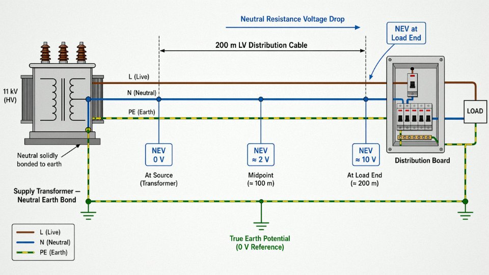
This is where the misunderstanding does real damage. Yes, the neutral is bonded to earth at the transformer, usually solidly in TN systems. But the conductor itself has resistance and, at higher frequencies, inductance. Current flowing through that resistance creates a voltage drop along the neutral conductor’s length. That voltage difference between the neutral at the load end and true earth potential is called neutral-to-earth voltage, or NEV.
On short factory runs it might be 1–2 V, negligible. On a long LV distribution feeder — say, 200 m or more of loaded cable feeding a rural substation or a remote building within a large site — NEV can reach 5–15 V under normal load, and considerably higher under fault conditions or during a neutral open-circuit event. Touch the neutral terminal on a distribution board at the far end of a long run with a ground fault present, and you can receive a shock from a conductor that was supposed to be at earth potential. Never assume it is safe simply because it is “the blue wire.”
Harmonic Loading Changes Everything About Neutral Sizing
IEC 60364-5-52 permits a reduced neutral cross-section in balanced three-phase circuits — typically down to half the phase conductor cross-section under certain conditions. That rule was written for the era of linear loads. Modern industrial environments are full of variable speed drives, switch-mode power supplies, UPS systems, and LED driver arrays. These generate odd-order harmonics, and the 3rd harmonic (150 Hz on a 50 Hz system) is the problem: it is a zero-sequence harmonic, meaning the 3rd harmonic currents from all three phases add arithmetically in the neutral rather than cancelling. A neutral conductor in a drive-heavy panel can carry 1.3–1.7× the phase current. Running a reduced neutral in that environment causes overheating, insulation degradation, and eventually a fire risk.
In circuits supplying significant harmonic-generating loads, the neutral conductor may need to be oversized relative to the phase conductors.True
IEC 60364-5-52 Annex C and the harmonic addition principle for zero-sequence currents (3rd, 9th, 15th harmonics) confirm that neutral current can exceed phase current in such circuits. This is a documented, well-established design requirement, not a conservative estimate.
The practical rule: if total harmonic distortion at the load is likely to exceed roughly 15–20%, specify a full-sized neutral as a minimum. Many experienced panel builders go to a neutral one size up from the phase conductors in VSD-heavy applications.
Insulation Rating: Match the Live Wire
Because the neutral is bonded to earth under normal conditions, there’s a temptation to treat it as a low-voltage conductor. Don’t. Under a line-to-neutral fault, or during an open neutral event in a TN-C-S system, the neutral can be elevated to full line-to-line voltage transiently. IEC 60446 and IEC 60502-1 both require that the neutral insulation withstand the same voltage stress as the live conductor insulation. In a 0.6/1 kV rated cable, every core — including the neutral, identifiable by its blue insulation per IEC 60446, or white/grey per NEC Article 200 — carries the same 1 kV dielectric rating.
Earthing System Configuration Drives Cable Construction Choices
How the neutral and earth relate physically depends entirely on which IEC 60364-1 earthing system you’re working within.
| System | Neutral and PE relationship | Cable construction implication |
|---|---|---|
| TN-S | Separate neutral (N) and protective earth (PE) throughout | 4-core or 5-core cable; dedicated green/yellow PE core required |
| TN-C | Combined PEN conductor throughout | 4-core cable acceptable; PEN conductor must meet both current-carrying and protective function sizing |
| TN-C-S | Combined PEN to a point, then separated | Split at main distribution board; cable from board onward must be TN-S construction |
| TT | Neutral from transformer; PE from local earth electrode | 4-core or 5-core cable; neutral and PE entirely independent |
| IT | Neutral may be absent or impedance-earthed | Often 3-core only; specialized for continuous-supply critical environments |
The TN-C configuration is worth a specific warning: the PEN conductor carries both return current and fault protection current simultaneously. Any break in it simultaneously creates a shock hazard on all exposed metalwork downstream. Modern practice — and IEC 60364 guidance — discourages TN-C in new installations, particularly anywhere with significant harmonic loading or where aluminium conductors are used (aluminium mechanical joints are a documented failure mode for PEN continuity).
How This Affects Multi-Core LV Cable Specification
In Jinda’s 4-core and 5-core low-voltage power cables built to IEC 60502-1 — typically with XLPE insulation, steel wire armour, and an outer PVC sheath — the neutral core is available in both full cross-section and reduced cross-section configurations. For a straightforward balanced three-phase motor feeder, the reduced neutral is a cost-effective choice. For a panel feeding a mixed load with multiple VSD outputs, LED lighting banks, and UPS-backed circuits, the full-sized neutral or an oversize option is the correct specification. Getting that choice wrong at the procurement stage means either rewiring later or accepting a thermal derating that eats into your cable’s current-carrying capacity from day one.
The Ground (Protective Earth) Wire: Fault Current Paths, Touch Voltage Limits, and IEC/NEC Compliance
The protective earth wire is the one conductor in a cable that should, under normal operation, carry exactly zero current. That is also what makes it so easy to neglect — and why failures in earth continuity tend to stay hidden right up until someone gets hurt or a piece of equipment fails catastrophically.
What the PE Conductor Actually Does
Its job is to connect every exposed conductive surface — motor frames, enclosure panels, conduit bodies, cable trays — back to the main earthing terminal at the supply source, through the lowest impedance path available. When a phase conductor faults to an exposed metal part, that low-impedance path forces a fault current large enough to trip the fuse, MCB, or RCD within the disconnection time required by IEC 60364-4-41. The whole mechanism is built around one number: touch voltage must not exceed 50 V AC (or 25 V in wet locations, construction sites, agricultural buildings — environments where skin resistance drops and the stakes rise). The PE conductor does not limit that voltage by absorbing it; it limits it by ensuring the protective device clears the fault fast enough that the voltage never persists long enough to be lethal.
If the earth path has too much impedance — corroded terminations, an undersized conductor, a broken continuity — disconnection time stretches, and touch voltage can remain dangerously high for seconds rather than milliseconds. That is the failure mode.
Sizing by the Adiabatic Equation
IEC 60364-5-54 and IEC 60909 provide the sizing equation engineers must apply:
S = (I × √t) / k
S is the minimum cross-section in mm², I is the prospective fault current in amperes at the point of installation, t is the protective device disconnection time in seconds, and k is a material-and-insulation constant: 115 for copper with PVC insulation, 135 for copper with XLPE, and 76 for aluminum with PVC. The equation is adiabatic — it assumes all heat generated by the fault is absorbed by the conductor itself, with no dissipation to surroundings, which gives a conservative result appropriate for the short durations involved (typically under 5 seconds, often under 0.4 s on final circuits).
IEC 60364-5-54 Table 54.2 permits the PE to be smaller than the phase conductor once the phase exceeds 16 mm² (copper) or 25 mm² (aluminum), provided the adiabatic check is satisfied. In practice, installers sometimes apply the simplified tabulated minima without running the fault-current calculation — particularly on industrial sites where prospective fault currents are high and disconnection times on upstream devices may be longer than assumed. Undersizing the earth wire is one of the most dangerous and least visible installation errors because it produces no symptoms until a fault occurs.
Physical Forms of the PE Conductor in Multi-Core Cables
Not every earthing conductor looks like a green-and-yellow core, though that is the standard identification required by IEC 60446 and most national variants. In Jinda multi-core flexible cables built to IEC 60228 Class 5 or Class 6, the PE is always a green-and-yellow insulated copper conductor sized and positioned per the cable’s rated design. In screened instrumentation and signal cables, a bare or tinned copper drain wire runs along the inner surface of the foil or braid screen and serves as the earth continuity path for that screen layer — a different function from the power earth, but the impedance requirements are equally real.
Armored cables introduce a third form. Steel wire armored (SWA) construction to IEC 60502-1 uses the armor itself as a combined mechanical protection and earth continuity conductor, which is accepted under IEC 60364-5-54 provided its impedance and fault-current capacity are verified by calculation. In practice, the SWA cross-section is usually adequate for the fault levels encountered in medium-voltage distribution, but it needs proper bonded glands at both ends — a loose or unconnected gland defeats the earth path entirely and is a surprisingly common site error.
PE Inside the Cable Versus the External Earthing System
The cable’s PE conductor is one link in a chain. IEC 62305 (lightning protection) and NEC Article 250 both require that chain to extend from the equipment chassis, through the cable PE, into the supply earth terminal, and onward to the electrode system — ground rods, earth mats, or equipotential bonding networks. A cable with a perfectly rated PE conductor provides no protection if the equipment chassis connection is floating or if the supply earth terminal is improperly connected to the electrode. Specifying the cable correctly is necessary but not sufficient.
Testing and Quality Verification
Jinda’s production quality process addresses PE performance at several points before cables ship. Conductor resistance is measured per IEC 60228 to confirm the cross-section is as specified — resistance being the practical proxy for cross-section on production lines. Spark testing on PE insulation (for the green-and-yellow cores in multi-core designs) checks that the dielectric integrity is intact along the full reel length. Hi-pot testing verifies insulation between conductors and between conductors and screen or armor. These tests are performed across Jinda’s five production bases, each with dedicated laboratory infrastructure, so that cables destined for international projects carry documented electrical verification rather than just dimensional conformance.
The IEC 60364-4-41 touch voltage limit is 50 V AC for normal dry locations and 25 V AC for wet or high-risk locationsTrue
IEC 60364-4-41 Section 411 specifies these limits as the basis for automatic disconnection of supply design, and they are reflected in most national implementations including BS 7671 and AS/NZS 3000.
One last operational note: the green-and-yellow color code is legally protected in most jurisdictions — it cannot be used for any conductor other than the PE. Using it for a neutral or a phase conductor to save reel stock is the kind of shortcut that creates genuinely dangerous confusion during maintenance, sometimes years after original installation.
International Color Coding Standards for Live, Neutral, and Ground Wires: IEC, NEC, AS/NZS, and Country-Specific Rules
Color coding is not decorative. A maintenance technician working in a 20-year-old industrial facility with mixed cable generations can suffer a fatal shock because a previous installer used colors from a superseded standard — and nothing on the panel flagged the discrepancy. This section is intended as a working reference, not a theoretical overview.
The Major Standards at a Glance
| Standard | Jurisdiction | Live / Phase | Neutral | Protective Earth |
|---|---|---|---|---|
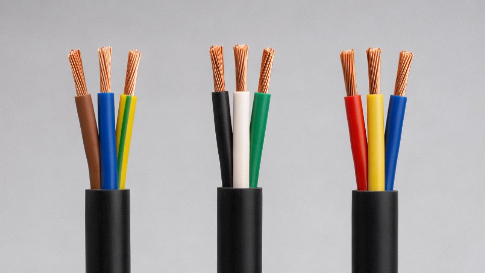
| IEC 60446 (current) | Global / Europe | Brown (L1), Black (L2), Grey (L3) | Blue | Green-Yellow |
| NEC / NFPA 70 | North America | Black (L1), Red (L2), Blue (L3) | White or Grey | Green or Bare |
| BS 7671 (post-2004) | United Kingdom | Brown (L1), Black (L2), Grey (L3) | Blue | Green-Yellow |
| AS/NZS 3000 (2018) | Australia / NZ | Brown (L1), Black (L2), Grey (L3) | Blue | Green-Yellow |
| IS 694 / NBC | India | Red (L1), Yellow (L2), Blue (L3) | Black | Green |
The IEC 60446 harmonization in 2004 pulled most of Europe, Australia, and eventually the UK into alignment. India stayed with its own legacy scheme, which matters because Indian-manufactured equipment exported to Europe or vice versa can arrive with confusingly mismatched conductor colors.
Why Old Colors Keep Showing Up — and Why That Is Dangerous
Before 2004 harmonization, the UK used red for live, black for neutral, and green-yellow for earth. Germany commonly ran grey for neutral and brown for live in single-phase circuits. If you are rewiring a section of a factory built in the 1990s, you may open a junction box and find both the old UK and the current IEC scheme in the same enclosure — red meaning live in one cable, red meaning nothing-standard in another. Electricians working fast under production pressure do not always stop to verify which era of wiring they are touching.
This is not hypothetical. It is the single most common root cause cited in electrical near-miss reports during renovation projects.
Legacy stock compounds the problem. Cable purchased years ago but only recently pulled from a warehouse reel can still carry the old color convention, and it is perfectly legal to install it in some jurisdictions provided the as-built documentation flags the discrepancy. In practice, the documentation gets filed and forgotten.
Three-Phase and Special-Service Colors
In three-phase IEC installations, L1/L2/L3 run brown, black, and grey — but note that grey was historically a neutral color in some Central European practices, which is exactly the kind of overlap that creates confusion in multinational plants. The old European three-phase scheme (brown, yellow, green) is now prohibited for new installations because green-yellow is permanently reserved for protective earth under IEC 60446.
NEC three-phase runs black, red, and blue for 480 V delta or 208 V wye systems. The NEC also permits grey as an alternative neutral — useful for multi-section switchgear where white conductors might be confused with small-signal wiring.
A few special cases deserve attention. DC circuits conventionally use red for positive and black for negative, though no single universal standard governs low-voltage DC the way IEC 60446 governs AC. High-voltage EV battery cables follow ISO 6469-3, which mandates orange for any conductor operating above 60 V DC or 30 V AC in the drive circuit — a hard rule in automotive supply chains. Medical and offshore IT-system installations sometimes designate violet or lilac for isolated conductors, though this varies by national implementation of IEC 61557-8.
Legal and Insurance Exposure
Non-compliant coloring can void equipment warranties, trigger failed third-party inspection certificates, and — in the event of a fault — give an insurer grounds to contest liability. The argument is straightforward: the installation deviated from the applicable wiring standard, the deviation contributed to the unsafe condition, therefore coverage is disputed. Courts in the UK and Germany have accepted this reasoning.
IEC 60446 harmonic color codes are legally mandatory in all EU member states for new fixed installationsTrue
The IEC 60446 color scheme was adopted into CENELEC HD 308 S2 and subsequently incorporated into national wiring regulations across EU member states, making brown/blue/green-yellow mandatory for new fixed electrical installations. Existing installations wired to older national color codes are grandfathered but must be documented.
How Jinda Handles Market-Specific Color Production
With customers across more than 50 countries, Jinda engineers color schemes at the specification stage rather than retrofitting labels. Phase insulation can be extruded in the target-country color or overprinted with sequential numbering per IEC 60445 — useful for multi-core instrumentation cables where the standard palette runs out of colors well before the conductor count does. Drum labeling and shipping documents reference the applicable standard explicitly: a reel destined for an Australian switchboard is marked AS/NZS 3000, not generically “IEC-compliant.” The technical support team maintains a country-standard matrix that gets updated when national codes revise, which is how procurement managers ordering 12-month forward stock avoid receiving cable that complies with a standard their local inspector no longer accepts.
How the Three Wires Scale into Three-Phase Systems: Phase Conductors, Neutral Sizing, and Earth in Industrial Power Cables
Single-phase theory gives you the foundation — live, neutral, earth, three conductors, clean logic. Step onto an industrial plant floor and the picture immediately gets more complicated. A 400 V three-phase distribution board feeding variable-speed drives, welding sets, and HVAC units is pulling from a system where those three wire functions multiply, interact, and sometimes conflict in ways that catch out engineers who learned wiring from residential textbook examples.
From Three Conductors to Four and Five
The jump from single-phase to three-phase doesn’t just add conductors arithmetically. A three-phase four-wire cable — three phase conductors plus a neutral, no separate PE — is common in older TN-C systems and in some North American commercial installations, but IEC practice for modern industrial sites has largely moved to five-core TN-S: three phases, a neutral, and a dedicated protective earth, all individually insulated, all separately sized. IEC 60502-1 is the governing standard for low-voltage power cables up to 1 kV, and five-core construction is what you’ll see specified on most European and Asian industrial projects today. The benefit is clean separation between return current (neutral) and fault current (PE) — which matters both for EMC and for protection relay coordination.
The 3-Core Plus Earth Shortcut — and When It Actually Works
In TN-S systems with steel wire armor (SWA), there’s a legitimate design shortcut: run a 3-core cable and use the SWA itself as the PE conductor, eliminating the separate earth core. This is explicitly permitted under IEC 60364-5-54, provided the armor’s cross-sectional area satisfies the adiabatic sizing equation and the termination glands give a reliable, low-impedance earth connection throughout the cable’s service life. In practice, the savings in cable diameter and material cost are real — roughly 10–15% on copper-heavy large cross-sections, though the exact figure depends on conductor size and armor specification. The operational risk is at the gland end: a corroded or undertightened SWA gland in a wet plant environment quietly degrades the PE path without triggering any alarm until there’s a fault. That’s a maintenance habit worth enforcing.
Neutral Sizing and the Harmonic Problem
In a perfectly balanced three-phase system, the neutral current is theoretically zero — the three phase currents cancel. Real plants are nowhere near that clean. Single-phase branch circuits, switch-mode power supplies, and variable frequency drives all inject third-harmonic currents that add in the neutral rather than cancel. In heavily distorted systems — data centers are the worst offenders, but modern commercial buildings with LED drivers and UPS equipment aren’t far behind — neutral current can reach somewhere between 135% and 173% of phase current, depending on the harmonic spectrum. Running a reduced neutral (50% of phase cross-section, which some older standards permitted) into that environment means an overloaded neutral conductor operating above its rated temperature, accelerated insulation aging, and eventual failure. For those applications, Jinda offers full-sized neutral options in its 4-core and 5-core XLPE/SWA/PVC range — same cross-section on the neutral as on the phase conductors — specifically because undersized neutrals have caused enough real-world problems that it’s worth the modest material premium to avoid them.
Concentric Neutral Design for Underground Distribution
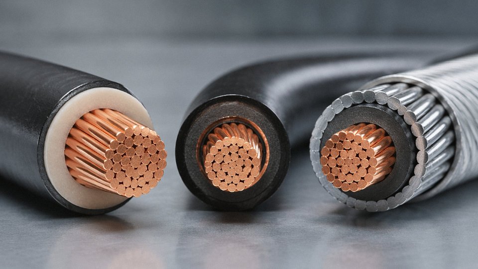
North American underground distribution uses a fundamentally different geometry. A concentric neutral cable has a single insulated phase conductor at the center; bare copper wires are laid helically over the insulation, serving simultaneously as the neutral return path and as an electrostatic shield. ICEA S-94-649 and AEIC CS9 govern the construction. The concentric wires are in direct contact with the surrounding soil or duct environment, which raises corrosion concerns in aggressive soils — copper is durable, but not immune to sulfide attack in some industrial ground conditions. This design is rare outside North America; engineers specifying cables for international projects need to be explicit about which system they’re designing to, because a North American utility engineer and a European industrial engineer can mean very different things when they say “three-phase cable.”
Stranding Geometry and Why It Matters Operationally
Multi-core cable assembly isn’t just a matter of bundling conductors together. The phase cores, neutral, and PE are stranded together with defined lay lengths — typically 8 to 15 times the cable diameter per turn, varying with construction class — to achieve mechanical balance, minimize differential thermal expansion stress, and produce a genuinely circular cross-section. That circularity matters more than it sounds: an out-of-round cable creates uneven compression in cable glands, which is a common source of ingress protection failures in IP54 and IP65 enclosures. It also makes conduit pulling harder, because the cable wedges rather than slides. Good stranding geometry, with appropriate fillers in the interstices, is what separates a cable that installs cleanly on a 200-meter conduit run from one that jams at the first bend.
Jinda's 4-core and 5-core XLPE-insulated, SWA-armored cables are produced to IEC 60502-1 and are available with optional third-party certification including KEMA, BASEC, and SGS verification.True
IEC 60502-1 is the published standard for 0.6/1 kV extruded solid dielectric insulated power cables, and third-party type testing by bodies such as KEMA (now KEMA-DEKRA), BASEC, and SGS is standard practice for cable manufacturers supplying international infrastructure and industrial projects.
The available range runs from 1.5 mm² up to 400 mm² per phase conductor, covering everything from sub-distribution boards in light industrial buildings up to main feeder cables in substations. Cross-section selection at the upper end of that range — anything above roughly 150 mm² — almost always warrants a thermal ampacity calculation specific to the installation method and ambient temperature, rather than relying on standard table values, because burial depth, soil thermal resistivity, and grouping factors can shift the continuous current rating by 20–30% in either direction.
Insulation, Sheathing, and Armoring Materials That Protect All Three Wire Types Throughout Cable Service Life
A cable’s three conductors — live, neutral, and earth — are only as reliable as the material layers wrapped around them. Get the insulation grade wrong for the ambient temperature, or specify PVC sheathing on a cable that runs through a cable tray in a rail tunnel, and you’re looking at premature failure, potentially a regulatory non-compliance issue, and in the worst case, a fire propagation path you didn’t design for.
Individual Core Insulation: The First Line of Defense
Each wire is insulated separately before the cores are laid up together. The choice of insulation material sets the cable’s thermal ceiling and its behavior under fault conditions.
PVC is the workhorse. Rated to 70°C continuous conductor temperature per IEC 60502-1, it’s inexpensive, easy to extrude, and perfectly adequate for general building wiring and light industrial installations. The dielectric strength typically runs 10–20 kV/mm depending on compound formulation and thickness. Its weakness is behavior in fire — it releases hydrogen chloride gas, which is corrosive and toxic in confined spaces.
XLPE pushes the envelope considerably. Continuous rating is 90°C, short-circuit tolerance reaches 250°C, and its dielectric strength is superior to PVC at equivalent thickness. Medium-voltage cables from roughly 3.6/6 kV upward almost universally use XLPE insulation, and in high-load LV installations where you’re trying to squeeze more current capacity out of a given cross-section, XLPE earns its cost premium. The cross-linked polymer structure resists deformation under sustained thermal load in a way that standard thermoplastic PVC simply cannot.
EPR — ethylene propylene rubber — occupies a specific niche that plant engineers in mining and offshore environments know well. Also rated 90°C continuous, EPR stays flexible at low temperatures and resists water penetration better than XLPE in submersed or wet-location service. On trailing cables in underground mines or on floating production platforms, EPR insulation holds up where XLPE can crack or stiffen over years of cyclic mechanical stress.
LSZH (low smoke zero halogen, sometimes written LSOH) is now mandatory in tunnels, rail rolling stock, public buildings, and offshore accommodation modules across most jurisdictions — IEC 61034 governs smoke density, EN 50268 covers halogen content. In a tunnel fire scenario, the difference between PVC and LSZH is measured in evacuation time. That’s not a specification footnote; it’s the reason the requirement exists.
Bedding, Armor, and the Outer Sheath
Between the laid-up cores and the armor sits the bedding layer — usually extruded PVC or LSZH compound. Its job is mechanical cushioning, a degree of moisture exclusion, and maintaining cable roundness within tolerances so the armor sits evenly. IEC 60502-1 specifies those roundness tolerances precisely because an oval cross-section concentrates armor stress unevenly.
Armor selection depends on installation conditions and the electrical configuration. Steel wire armor (SWA) handles direct burial, duct installations with risk of mechanical damage, and vertical risers. Steel tape armor (STA) gives longitudinal rigidity where that matters — pull-through in conduit on long runs, for instance. For three-phase single-core cables, aluminum wire armor (AWA) is the correct choice; a steel armor on a single-core AC cable creates a shorted magnetic circuit and eddy-current heating that can easily add 10–20% to your losses, sometimes more depending on cable size and load factor. Braided armor, meanwhile, shows up on flexible industrial trailing and drag-chain cables where the bending radius changes constantly during operation.
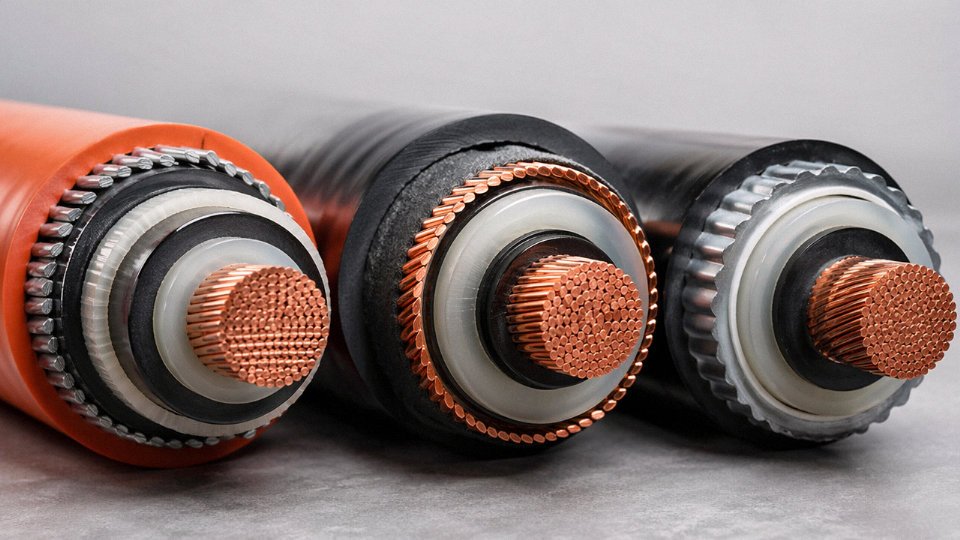
The outer sheath is the cable’s face to its environment. PVC Type ST2 is the global default for fixed installations — cost-effective, mechanically reasonable. Polyurethane (PUR) sheathing handles high-flex drag-chain applications where a PVC sheath would crack within months. LSZH Type SHF2 is specified for rail, offshore, and public infrastructure for the same fire-safety logic as LSZH insulation. Chlorinated polyethylene (CPE) resists oil splash and UV degradation, making it the sensible call for outdoor industrial equipment and petrochemical plant installations. Sheath color also carries market-specific meaning — black for outdoor UV resistance, grey for general indoor fixed wiring in many European specifications, orange as the conventional marker for instrumentation and signal cables in process plant environments.
Service Life and Why Material Control Matters
A 30-year design life — standard for infrastructure projects like substations, rail, and offshore platforms — isn’t achieved by meeting minimum specification at the point of manufacture and then hoping. Thermal aging per IEC 60216, chemical resistance testing per IEC 60811, and mechanical abrasion tests need to be run on the actual compound batches used in production, not just on reference samples from a material datasheet.
Jinda's cables are manufactured across five production bases with fully in-house compounding, conductor drawing, stranding, extrusion, and armoring lines within 470,000 m² of manufacturing spaceTrue
This is consistent with Jinda's published manufacturing profile and is a verifiable operational fact about their vertical integration, not a marketing claim about product performance
That vertical integration — controlling the compound formulation, the extrusion process parameters, and the armor fabrication under one quality system — is what allows consistent layer thicknesses and material properties from the first drum to the ten-thousandth. For a procurement manager sourcing 500 km of MV cable for a grid project, that consistency matters more than a marginally lower unit price from a supplier who buys compound on the open market and extrudes it on contract lines.
Practical Selection Checklist: Matching Live, Neutral, and Ground Wire Specifications to Your Project Requirements
Getting the theory right matters. Getting the specification sheet right is what keeps a project from going back out to tender six weeks before energization.
Work through these steps in order. Each one feeds into the next, and skipping Step 2 to jump straight to insulation selection is how you end up with a correctly insulated cable that overheats under load.
Step 1 — Nail Down the Electrical System Parameters First
Before you open a conductor cross-section table, confirm: AC or DC, nominal and maximum system voltage, frequency (50 Hz or 60 Hz matters for reactive voltage drop calculations), and the earthing arrangement — TN-S, TN-C-S, TT, or IT. These are not administrative details. The earthing type directly controls how your protective earth conductor is arranged within the cable and whether a combined PEN conductor is even permissible (spoiler: PEN is only allowed at 10 mm² copper or 16 mm² aluminum and above under IEC 60364).
Get the prospective short-circuit current (Isc) in kA at the point of connection from the network operator or from your switchboard fault-level study. This, combined with the required disconnection time from your protection relay settings, feeds directly into the PE conductor sizing in Step 4. Without it, you are guessing.
Step 2 — Calculate Phase Conductor Cross-Section Properly
Pull IEC 60364-5-52 for current-carrying capacity. The base tables assume 30°C ambient and a specific installation method — direct buried, in free air, on a perforated tray, clipped to a wall. Each of those conditions gives a different starting capacity for the same conductor size.
Apply derating factors honestly. Ambient temperatures above 30°C reduce capacity; in tropical plants or rooftop cable trays in summer, that correction can cut rated current by 15–25% depending on conductor type and insulation. Cables bundled in conduit or laid touching in a tray see grouping factors that can drop capacity further, sometimes below 0.7 for a tightly packed bunch of eight or more circuits. In practice, engineers sometimes underestimate this when laying out a new tray route and then wonder why the upstream breaker nuisance-trips in August.
Verify voltage drop independently. IEC 60364-5-52 caps it at roughly 4% for power circuits and 3% for lighting. Long runs — anything over 80–100 m at lower voltages — often require a larger cross-section for voltage drop compliance than for thermal compliance. Note that in the cable schedule, so the next engineer reviewing the design understands why a 16 mm² conductor was specified on a circuit that thermally only needed 10 mm².
Step 3 — Make a Deliberate Decision on Neutral Sizing
For single-phase circuits: neutral equals phase. Full stop. For three-phase circuits, a reduced neutral (typically 50% of the phase cross-section) is only defensible if you have low harmonic distortion — THDi consistently below roughly 15%. If the load is variable-speed drives, switched-mode power supplies, UPS systems, or any mix of non-linear loads, the triple-n harmonics (3rd, 9th, 15th) add in the neutral rather than cancel, and an undersized neutral will overheat even when the phase conductors are running comfortably within rating. Document the harmonic assumption in the cable schedule. If you are wrong, the cable manufacturer is not liable — you are.
Step 4 — Size the Protective Earth Conductor Using the Adiabatic Equation
The adiabatic equation: S = (I × √t) / k
S is the minimum conductor cross-section in mm², I is the fault current in amperes, t is the disconnection time in seconds, and k is a material constant — 115 for 70°C PVC-insulated copper, 143 for thermosetting-insulated copper, roughly 76 for aluminum. Typical disconnection times range from 0.1 s on fast MCBs up to 5 s where IEC 60364-4-41 permits it for certain distribution circuits, and that difference produces a factor of more than 7 in the required cross-section.
Cross-check the adiabatic result against the minimum PE size table in IEC 60364-5-54. Whichever gives the larger cross-section governs. If you are relying on the cable armor or a concentric neutral conductor as the PE path, it must satisfy the same adiabatic equation — verify this with your cable manufacturer using the actual armor cross-section they will supply, not a nominal value from a catalog.
Specify green-yellow insulation on the PE conductor explicitly in the cable datasheet. In LV systems, connect it to the main earthing terminal at both ends. This is one of those requirements that seems obvious until someone on site leaves the PE disconnected at the load end “temporarily” during commissioning and then forgets about it.
The adiabatic equation S = (I × √t) / k gives the minimum PE conductor cross-section required to survive a fault without insulation damage before the protective device clears.True
This formula is the basis of PE sizing in IEC 60364-5-54 and BS 7671. It accounts for the energy deposited in the conductor during fault clearance, assuming adiabatic heating (no heat lost to surroundings during the short event). The k values are material- and insulation-specific and are tabulated in the standard.
Step 5 — Match the Insulation and Sheathing System to the Real Installation Environment
Operating temperature sets the starting point. PVC is adequate to 70°C conductor temperature and handles most standard LV installations; XLPE takes you to 90°C continuous and 250°C short-circuit, which meaningfully improves current-carrying capacity for the same cross-section. EPR offers similar thermal ratings to XLPE with better flexibility in cold conditions — relevant if the cable is being installed in northern sites in winter or in refrigeration plant rooms where PVC can stiffen and crack during handling.
Then layer in the environment. Direct buried in corrosive soil needs an armored construction with appropriate bedding, usually steel wire armoring (SWA) for round cables or steel tape armoring for flat cables, covered by a PE or PVC outer sheath rated for soil contact. Offshore or coastal installations need to think about UV resistance, salt fog, and sometimes dynamic bending cycles if the cable runs to movable equipment. ATEX zones require cables certified to the applicable equipment group and temperature class. Fire performance requirements — IEC 60332-3-24 for flame propagation in bunched cables, IEC 61034-2 for smoke density, IEC 60754-1/2 for halogen content — need to be specified explicitly; they are not automatic in a standard LV cable, and in a school, hospital, tunnel, or other public building, they are usually mandatory and sometimes locally enforced.
Step 6 — Lock In Color Coding, Documentation, and Test Evidence
Specify the color coding standard for the destination country in the cable datasheet — IEC 60446, NEC Article 310, AS/NZS 3000, or whichever applies. Do not leave this to the manufacturer’s default, especially on cross-border supply.
Request test reports to IEC 60228 for conductor resistance verification, IEC 60811 series for insulation and sheath mechanical and ageing properties, and IEC 60502-1 (for 1–30 kV extruded cables) or IEC 60245 (for rubber-insulated cables) for complete cable construction testing. A manufacturer who cannot produce these reports for a specific cable type should raise a flag.
Once you have worked through this checklist, compile the cable schedule — one row per circuit, capturing system voltage, Isc, phase cross-section, neutral sizing rationale, PE cross-section with the adiabatic calculation documented, insulation system, and applicable standards — and bring that document to your cable supplier. Jinda’s technical team can take a completed specification and provide a formal quotation covering production, testing, and delivery to your project site.
Frequently Asked Questions About the Three Types of Wires in a Cable
Can I bond the neutral and ground together at the load-side panel?
No — and this mistake causes more nuisance faults and genuine shock hazards than most installers realize. When you tie the neutral and PE together at a downstream distribution board or load panel, you create a parallel return path: neutral current starts flowing back through the PE conductor and through any metallic conduit, cable armor, or equipment chassis connected to it. That chassis is now live under normal operating conditions, not just during a fault. IEC 60364-4-41 prohibits this explicitly in TN-S systems downstream of the point of separation, and NEC 250.142(b) restricts neutral-PE bonding to the service entrance or the separately derived system’s first disconnecting means. The permitted bonding point is the transformer star point or main service panel — once, not repeatedly. In practice, the error often creeps in during panel upgrades when an electrician copies the main panel wiring arrangement without recognizing the difference between a service entrance and a sub-panel.
Why does my ground wire sometimes carry measurable current?
A healthy PE conductor carries zero current in steady state, but several real-world phenomena push small currents onto it. Long LV and MV cables have distributed capacitance between conductors and screen or armor; charging and discharging that capacitance generates a continuous leakage current that returns via PE. In a 500 m armored LV feeder this can easily run 5–20 mA depending on cable type and voltage level. Variable speed drives are a bigger contributor — their EMC filter capacitors (the Y-capacitors to earth) dump high-frequency discharge current onto the PE, sometimes continuously in the range of 10–100 mA per drive. That’s why VSD manufacturers specify minimum PE conductor cross-sections separately from the current-carrying calculation. Actual ground fault current is obviously different in magnitude and duration and will trip an RCD within 40 ms at the thresholds IEC 62423 specifies. If you’re seeing steady-state PE current above roughly 30 mA on a circuit without drives, investigate immediately — you likely have insulation degradation or a hidden neutral-PE bond somewhere in the installation.
“Three-wire cable” versus “three-conductor cable” — aren’t they the same thing?
Not always, and ordering the wrong one is an easy procurement error. In single-phase wiring, “three-wire” colloquially means live + neutral + earth — three insulated conductors, one of which is the protective earth. In three-phase industrial supply, “three-conductor” typically means three phase conductors with no neutral at all, used in balanced three-phase loads like motors. Specify by number of cores plus whether a separate earth core is included: “4-core with earth” or “3C+E” is unambiguous. “Three-wire” alone is not. When issuing a purchase order, always state conductor count, whether earth is a separate insulated core or a concentric wire, and whether neutral is required.
IEC 60364-4-41 prohibits neutral-PE bonding at load-side panels in TN-S systemsTrue
IEC 60364-4-41 clause 411.4.2 requires that in TN-S systems the neutral and protective earth conductors must remain separated throughout the installation downstream of the separation point; bonding them downstream creates parallel return paths that place touch voltage on exposed conductive parts under normal load conditions.
How do I identify the three wires in an old cable with faded or non-standard colors?
Carefully, and with the right sequence. First, apply lockout-tagout — do not skip this. With power isolated, use a continuity tester to find the PE: it will show continuity to the main earthing bar or equipment chassis. In most installations that’s unambiguous. Then restore power temporarily and use a non-contact voltage tester to identify the live conductor. The remaining core is neutral by elimination. Never rely on color coding alone in any renovation touching pre-2004 European wiring or pre-1970s North American wiring — the old harmonized colors in Europe (red = live, black = neutral, green = earth in some markets) overlap directly with current IEC colors used for different functions. Label everything before you cut.
Does the ground wire cross-section have to match the live wire?
Up to 16 mm² copper phase conductor, yes — IEC 60364-5-54 Table 54.2 requires the PE to be at least equal to the phase cross-section. Above 16 mm², the PE can step down to half the phase cross-section, but only if the adiabatic equation check (k²S² ≥ I²t) confirms that it won’t overheat before the protective device clears the fault. NEC Table 250.122 follows similar graduated sizing. Undersizing the PE is common in the field, especially where installers use the neutral size as a proxy — and it’s dangerous because an undersized PE that fails during a fault can sustain arcing long enough to cause a fire.
What certifications confirm the three wire types are correctly constructed?
For LV power cables, request an IEC 60502-1 type test report — this covers conductor resistance, insulation voltage withstand, and marking requirements for all cores. Flexible cables sold into Europe should carry HAR marking under the CENELEC harmonization scheme, which verifies color coding and mechanical performance across participating national standards bodies. North American projects need UL 44 (thermoset-insulated wire) or UL 83 (thermoplastic-insulated) listing. Australian projects require AS/NZS 5000.1 compliance. Beyond self-declarations, request third-party laboratory test reports from accredited bodies — SGS, TÜV, and KEMA are the names most procurement departments recognize and accept. Jinda’s standard and custom cable ranges carry the relevant certifications for each target market, with test documentation available on request for project-specific procurement packages.