Specify the wrong connector type on a cable assembly drawing, or let a procurement shortcut slide through without checking IP rating against the installation environment, and you will pay for it well after the initial purchase order is closed. Connectors fail at the joint before the cable itself does — vibration loosens an under-specified circular connector, moisture bridges into an IP54-rated housing deployed outdoors in a coastal climate, or a high-cycle USB interface wears past its 1,500-cycle contact life and starts dropping signal intermittently in a production test fixture. That intermittent failure mode is the worst kind: hard to reproduce, expensive to diagnose, and easy to misattribute to firmware or the cable run itself rather than the connector sitting right in front of you.
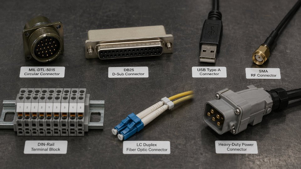
The seven main types of cable connectors are circular connectors, rectangular/D-sub connectors, USB connectors, coaxial (RF) connectors, terminal block connectors, fiber optic connectors, and power connectors. Each type is defined by its contact geometry, mating mechanism, and the electrical or optical signal it is designed to carry — and choosing between them depends on current load, environment, mating frequency, and whether the connection needs to be field-serviceable.
What makes this genuinely complicated is that the categories overlap in practice. A circular connector can carry power, signal, or both simultaneously. A terminal block can be rated for low-signal instrumentation or 600 V mains. Contact resistance alone — which swings from under 5 mΩ on a fresh, correctly crimped copper alloy contact to well over 50 mΩ once corrosion or a cold crimp takes hold — can be the difference between a stable power rail and a connector that runs hot enough to melt its own housing. Understanding what separates these seven families, and where each one earns its place on a panel or in a cable assembly, is worth getting right before the bill of materials goes out.
Type 1 — Circular Connectors: The Workhorse of Heavy Industrial and Defense Wiring
The cylindrical shell is not a styling choice. It’s an engineering decision. A circular cross-section distributes radial stress evenly around the mating interface, which means the connector resists pull-out, side-load, and torsion far better than a rectangular housing of comparable size. Pair that geometry with a continuous circumferential O-ring seal and a threaded or bayonet coupling ring, and you have a connector that can survive sustained vibration, pressure washing, and temperature cycling that would split a D-sub or terminal block assembly in weeks. That’s why circular connectors dominate every application where the environment is hostile and disconnection is expensive.
The Main Subtypes and Where They Come From
MIL-DTL-5015 is the older MIL-spec family — designed in the 1940s, still in production. Shell sizes run from 8 through 48, supporting roughly 2 to 100+ contacts depending on insert arrangement. Current ratings typically span 7.5 A to 200 A per contact depending on contact size, and the threaded coupling makes it nearly vibration-proof without any secondary locking hardware. You’ll find these on military ground vehicles, legacy industrial controls, and anywhere that the purchasing department has been buying the same part since before the internet existed.
MIL-DTL-38999 came later and is meaningfully more capable — higher contact density (up to 128 contacts in a Series III shell), quadruple-start bayonet or threaded coupling for faster mating, and better EMI backshell options. Weight-sensitive aerospace and defense platforms almost always specify 38999 Series III. The connector is more expensive, and the contacts are fussier to crimp correctly, but contact resistance on a properly assembled 38999 stays comfortably under 5 mΩ. Let a field technician crimp those contacts with undersized tooling and you can easily see 30–50 mΩ, which on a signal circuit means intermittent faults that are nearly impossible to chase down on a live platform.
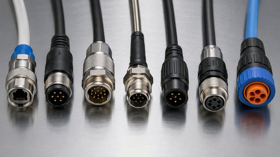
M12 and M8 are the industrial Ethernet and sensor world’s answer to the same problem. M12 connectors — coded A, B, C, D, or X depending on pin arrangement and frequency — handle 4 to 8 contacts, up to roughly 630 V and 12 A (coding-dependent), and are the default choice for machine-mounted proximity sensors, encoders, and industrial Ethernet runs where you need IP67 with fast field-assembly. M8 is physically smaller, used where panel space is tight. Both use a push-pull or screw coupling. In a high-cycle assembly environment — say, a robotic welding cell where the cable flexes thousands of times per shift — M12 connectors rated for 5,000+ mating cycles are a reasonable expectation, but only if the cable itself is a PUR-jacketed, torsional-flex rated assembly. Putting a standard PVC cable on a robot arm and expecting the connector to be the failure point is wishful thinking.
Harting’s Han series sits in a different bracket: modular rectangular-shell inserts in a circular-style housing, designed for combination power, signal, and pneumatic/data in a single panel-mount housing. Common in packaging machinery and press lines.
Sealing, Locking, and the Choices That Actually Matter
IP67 and IP68 are the dominant ratings for outdoor and industrial circular connectors. IP67 covers immersion to 1 m for 30 minutes; IP68 extends that to continuous submersion beyond 1 m, with the exact depth and duration specified by the manufacturer. Both depend on an elastomeric O-ring face seal compressed during mating, combined with a cable gland or clamp that seals the jacket entry. The locking mechanism is a separate decision: bayonet is faster to mate and preferred on rail rolling stock and wind turbine nacelles where maintenance windows are short; threaded coupling gives more positive engagement under continuous vibration and is standard on oil and gas field instrumentation where accidental disconnection has serious consequences.
Shell material is where procurement teams regularly make expensive mistakes. Zinc die-cast shells are fine for indoor automation panels — they’re cheap and they work. Put one on a nacelle at an offshore wind site or a chemical plant where wash-down includes alkaline cleaners, and you’ll be replacing corroded connectors within two seasons. Stainless steel shells cost roughly 3–5× more but last the life of the installation. Glass-filled composite shells split the difference: lighter than stainless, corrosion-resistant, but not rated for continuous mechanical abuse. Match the shell to the actual environment, not the best-case scenario.
Circular connectors with proper IP68 sealing and stainless steel shells can maintain contact resistance below 5 mΩ after prolonged submersion in clean waterTrue
Validated by IEC 60512 test procedures; the O-ring face seal and cable gland prevent moisture ingress at the contact interface, while stainless construction resists galvanic corrosion that would otherwise degrade the contact surface.
Mating cycle specification is the most under-specified parameter in industrial circular connector procurement. A maintenance technician on a predictive-maintenance program who disconnects a machine-mounted junction box quarterly will accumulate 40 cycles over ten years. A robotic end-of-arm tool connector might see 40 cycles in a single shift. Both look like “M12 connectors” on a BOM, but they need completely different products.
Type 2 — Rectangular / Modular Connectors: Scalable Power and Signal in Control Panels
Rectangular connectors don’t get the same romantic treatment as circular M12s or heavy-duty MIL-spec shells, but walk through any serious control panel build and they’re everywhere — DIN-rail mounted, stacked in hoods, carrying 24 V DC signals right next to 400 V power feeds, sometimes with a pneumatic insert squeezed in the same housing. That geometric flexibility is precisely the point.
Why the Rectangular Housing Geometry Matters
The flat, rectangular shell lets you pack contacts in a grid — typically two to four rows — at consistent pitch spacing, which translates directly into cabinet real estate. A circular connector carrying 24 contacts needs a much larger footprint clearance due to its round flange; a rectangular equivalent sits flush against a din rail or panel cutout, bolts down with two screws, and shares a row with six identical connectors without wasted space between them. For machine builders shipping to customers who will eventually add axes, I/O expansions, or additional field devices, that scalability matters from day one.
Key Families and Their Practical Specs
D-Sub connectors (DB9, DB15, DB25, DB37, DB50) still appear constantly in legacy instrumentation, motion controllers, and HMI rear panels. Contact pitch is 2.74 mm, current ratings sit around 3–5 A per contact depending on conductor gauge and ambient conditions. They’re cheap, globally stocked, and well understood — but the zinc die-cast shells on budget versions corrode surprisingly fast in humid environments. Use them for signal; don’t lean on them for sustained power loads.
Han modular systems from Harting operate on a different philosophy entirely. You select a hood size — Han 10B, 16B, 24B, and so on — then populate the interior with interchangeable inserts: 16 A power modules, Cat 6 data inserts, pneumatic couplings, fibre-optic pass-throughs. One connector on a machine’s control cabinet door replaces what used to be eight separate penetrations. Contact pitch varies by insert type, but the 6 mm² power inserts are typically rated 16–40 A per contact depending on the module and de-rating applied. In practice, most panel builders de-rate by 20–30% when the enclosure ambient exceeds 40 °C.
Molex Mini-Fit Jr. is the go-to in lower-voltage DC power distribution — 4.2 mm pitch, contacts rated around 9–13 A per pin depending on wire size and current-sharing across a multi-pin housing. Common in machine internal wiring, not so much at the panel interface level.
Phoenix Contact COMBICON (and equivalent Wago, Weidmüller screw/spring cage variants) handle the signal end: 3.5 mm and 5.08 mm pitch, rated roughly 8–12 A per contact, but used almost universally for low-current signal and communication lines where the benefit is tool-free field wiring, not ampacity.
Insert-and-Hood Assembly Logic
The real operational value of the modular approach is connector count reduction. A mid-size assembly cell might bring power, DeviceNet, safety signals, and compressed air into the control cabinet through a single Harting hood. That means one mated interface to disconnect for machine relocation or maintenance — minutes, not an hour of tracing individual cables. Specify the hood size first based on the worst-case future expansion, then populate inserts for current scope. Leaving one blank slot costs almost nothing upfront and avoids a hood replacement later.
Shielding and EMI Considerations
VFD-heavy floors are brutal on signal integrity. Metal hoods with conductive EMI gaskets and backshell grounding to the cabinet earth rail are not optional in those environments — they’re baseline. A floating shield terminated only at one end will help with electric field noise but won’t suppress the common-mode interference that PWM drives generate at 2–16 kHz switching frequencies. Ground both ends through low-impedance bonding when the drive cabinet and control cabinet share a common earth.
Poor or corroded contact connections in rectangular modular connectors can raise contact resistance from under 5 mΩ to over 50 mΩ, significantly increasing heat generation at the mating interface.True
This matches established connector engineering benchmarks: high-quality copper alloy crimp contacts achieve under 5 mΩ; oxidation, contamination, or mechanical damage to the contact surface increases resistance, and at sustained current, even a modest resistance increase generates disproportionate heat due to I²R losses.
Panel-Builder Checkpoints
Current de-rating at elevated temperature is the one thing junior panel builders routinely skip. Most connector datasheets publish ratings at 20–25 °C free air; in a sealed cabinet running at 55 °C ambient, derate by at least 25–35%. Keying — physical polarisation pins inserted into the hood — prevents mis-mating between identical-looking connectors serving different voltage levels, and IEC 61984 compliance should be verified before specifying any connector for safety-relevant circuits. It’s not a rubber stamp exercise; the standard covers contact retention force, insulation resistance, and dielectric withstand, all of which interact with the insert choice you made at the start.
Type 3 — RF Coaxial Connectors: Signal Integrity From Antenna to Instrument
A coaxial connector is deceptively simple looking — a pin in the middle, a barrel around it, some dielectric between the two. That geometry is precisely the point. The center conductor carries the RF signal; the outer shell acts simultaneously as ground return and electromagnetic shield; and the dielectric spacer sets the characteristic impedance of the interface. Get any of those three elements mismatched and you don’t get a marginal degradation — you get reflections, standing waves, and signal loss that compound with frequency. At 100 MHz you might tolerate a sloppy connection. At 6 GHz it will wreck your measurement.
The two dominant impedance standards are 50 Ω and 75 Ω, and they are not interchangeable in practice even though the connectors sometimes physically mate. Fifty-ohm systems handle RF power transmission and most test-and-measurement work — antenna feeds, radar front ends, lab instruments. Seventy-five ohm is the broadcast and CATV world, optimized for minimum attenuation in long passive distribution runs. Connecting a 50 Ω source to a 75 Ω coax assembly without a proper impedance match introduces a VSWR around 1.5:1 at the junction and measurable insertion loss that grows with frequency. In a short cable run for a home TV that might be barely noticeable. In a headend distribution system or a calibrated antenna test range, it corrupts the data.
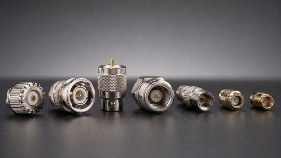
Connector Family Breakdown
The table below covers the families you’ll actually encounter on real projects, not an exhaustive catalog.
| Family | Usable Frequency Range | Coupling | Primary Application | Notes |
|---|---|---|---|---|
| BNC | DC – 4 GHz | Push-and-twist bayonet | Lab instruments, video, legacy RF | Quick-mate; avoid above ~1 GHz for precision work |
| TNC | DC – 11 GHz | Threaded | Vibration-prone RF assemblies | Essentially a threaded BNC — better VSWR at higher frequencies |
| SMA | DC – 18 GHz | Threaded (3.5 mm) | Microwave modules, antennas, PCB transitions | Very common; quality varies enormously by manufacturer |
| N-type | DC – 11 GHz | Threaded, weatherproof | Outdoor antenna base stations, test ports | Robust; handles higher power than SMA |
| F-type | DC – 3 GHz | Threaded (uses center conductor as pin) | CATV, satellite dish LNB feeds | Inexpensive; center conductor is literally the cable’s inner wire |
| 2.4 mm / 2.92 mm | DC – 50 GHz+ | Precision threaded | Millimeter-wave test, 5G mmWave | Handle only with calibrated torque tools; one bad mate can shift calibration |
BNC is still everywhere in older test environments and broadcast plants — I’ve seen racks of them running 20 years of continuous patch-and-re-patch duty without issue at the frequencies involved. SMA is the default for anything above a few gigahertz in compact form factor, but the quality spread between a $2 SMA from an unknown supplier and a precision connector from a reputable house is significant. The dielectric concentricity on the cheap parts is often off enough to create impedance discontinuities you can see clearly on a vector network analyzer.
VSWR and Insertion Loss: What “Acceptable” Actually Means
VSWR below 1.5:1 across the rated frequency range is a reasonable minimum threshold for general RF work. High-quality connectors typically achieve 1.15:1 to 1.35:1. Insertion loss should sit below roughly 0.2–0.3 dB at rated frequency for a single connector interface; if you’re seeing 0.5 dB or more per connection in a low-GHz application, something is wrong — usually a poorly trimmed dielectric, an off-center pin, or a contaminated mating surface.
Contact resistance in coaxial connectors has a direct effect on RF insertion loss and thermal performance at high power.True
Higher contact resistance at the center pin or outer shell interface increases ohmic loss, raising insertion loss and generating localized heating — both of which degrade signal integrity, especially as frequency and power level increase.
Cable-to-Connector Matching Is Not Optional
Every coaxial connector is dimensioned for a specific cable outer diameter range and dielectric type. Using an SMA designed for semi-rigid 0.085″ cable on a flexible RG-405 assembly without checking the crimp ferrule spec is a common mistake that creates an air gap at the dielectric interface — an immediate impedance discontinuity. Braid coverage percentage matters too: cables with 90–95% braid coverage maintain the shield integrity the connector geometry assumes. Drop below 85% and shielding effectiveness degrades, which shows up as noise pickup and erratic VSWR at the upper end of the frequency range.
Installation Pitfalls That Actually Happen
Over-crimping the center pin is probably the most common assembly error. The pin compresses slightly, shifts off-axis relative to the outer body, and the resulting eccentricity causes a predictable impedance bump. A good crimp tool with the correct die set and a go/no-go gauge prevents it — but shops that do mixed-connector assembly often don’t bother swapping dies between connector families.
Dielectric trim length is equally unforgiving on precision connectors. The spec exists because the distance from the end of the dielectric to the reference plane of the mating interface is part of the electrical model. Trim too short, you introduce an air gap. Trim too long, the dielectric interferes with mating. On 2.4 mm or 2.92 mm connectors used in millimeter-wave test setups, always use a calibrated torque wrench — typically 0.9 N·m for 2.4 mm interfaces, give or take depending on the specific connector body. Hand-tightening those connectors is how calibration standards get damaged.
One operational warning worth stating plainly: never mate a 50 Ω precision connector to a 75 Ω connector to “test if it works.” Even if the physical coupling doesn’t immediately damage the parts, you’re introducing an impedance step that invalidates any measurement you make, and at millimeter-wave frequencies, partial engagement during the mating process can gouge the contact surfaces of a connector that costs $80–$400 a piece.
Type 4 — Fiber Optic Connectors: Zero EMI Data Transmission for High-Speed Industrial Networks
Fiber optic connectors operate on an entirely different set of physics than anything covered in the previous three connector types. There is no electrical contact to corrode, no contact resistance to measure in milliohms, no concern about galvanic incompatibility between dissimilar metals. What you are managing instead is light — specifically, the alignment of two glass cores that can be as narrow as 9 µm, a dimension roughly one-tenth the width of a human hair. Get that alignment wrong by even a few micrometers, and you’ve introduced loss that can cascade into link failures, retransmission overhead, or outright network downtime. This is a discipline where cleanliness and geometry dominate, not torque specs or contact plating thickness.
Why Contamination Is the Real Enemy
The most common cause of fiber connector failure in industrial environments isn’t mechanical damage — it’s a fingerprint, a dust particle, or residual cleaning solvent on the endface. A single 1 µm particle sitting on a 9/125 µm single-mode core can introduce 0.5 dB or more of insertion loss by itself. In practice, the rule on any plant floor should be: never mate a fiber connector you haven’t inspected with a fiber scope first. That takes roughly 30 seconds and catches the majority of problems before they become troubleshooting hours.
Angular misalignment matters too. IEC 61300-3-4 defines acceptable endface geometry parameters — fiber protrusion (height), radius of curvature, and apex offset — and connectors that fall outside these tolerances will mate poorly regardless of how clean they are. Ferrule quality is not uniform across suppliers, and this is one area where buying the cheapest field-terminated connector off a catalog is a false economy.
Connector Types You’ll Actually Encounter
SC (push-pull, square body) remains the default for data center patch panels and structured cabling where density is moderate and the push-pull latch allows single-handed operation. It’s not particularly compact, but it’s robust and widely stocked.
LC has largely displaced SC in high-density applications — LC’s 1.25 mm ferrule versus SC’s 2.5 mm means you can fit roughly twice as many ports in a given panel space. Most modern SFP and SFP+ transceivers use LC duplex. If you’re specifying a new industrial Ethernet backbone today, LC is the default choice unless the installed base forces otherwise.
ST (bayonet twist-lock) is legacy at this point. You’ll still find it in older factory automation networks and campus fiber runs installed in the 1990s and early 2000s. It works fine, but plan around it rather than specifying it new.
FC (threaded coupling) is worth knowing specifically for vibration-prone environments — machine tool enclosures, compressor rooms, anywhere with sustained mechanical vibration that would gradually unlock an SC latch or ST bayonet. The threaded body stays put. FC is also common on optical test instruments and OTDR ports.
MTP/MPO is a different category entirely: multi-fiber ribbon connectors carrying 8, 12, or 24 fibers in a single push-pull housing. These are the trunk connectors for 40G and 100G parallel optic links. They’re fast to deploy in pre-terminated cassette systems, but MTP endface inspection requires a specialized probe, and a contaminated MTP connector affects all fibers simultaneously.
Loss Budgets and Ferrule Tolerances
Target insertion loss for a well-made mated pair is ≤ 0.3 dB; in practice, a clean factory-polished LC or SC connector runs 0.1–0.2 dB. Return loss is equally important on single-mode links: a standard PC (physical contact) polish achieves ≥ 40 dB, which is adequate for most Ethernet and industrial fieldbus applications. APC (angled physical contact, identifiable by the green housing) achieves ≥ 60 dB return loss and is mandatory for passive optical networks, DWDM, and any application where back-reflection would destabilize a laser source.
Single-mode fiber (9/125 µm) demands ferrule bore tolerances of roughly ±0.5 µm to keep core-to-core misalignment within acceptable bounds. Multimode (50/125 µm or 62.5/125 µm) is more forgiving — ±1–2 µm ferrule tolerance is generally acceptable — which is part of why multimode systems are easier to terminate in the field and still hit loss targets.
APC-polished fiber connectors achieve return loss of 60 dB or greater, making them mandatory for wavelength-division multiplexed and passive optical network applications.True
APC connectors use an 8-degree angled endface that reflects back-reflections away from the fiber core at an angle, achieving ≥60 dB return loss per IEC 61300-3-4, versus ≥40 dB for standard PC polish. This is a well-established fiber optic specification.
Field Termination vs. Factory Pigtails
For permanent backbone runs — say, a trunk between a main control room and a remote I/O cabinet — fusion-spliced factory pigtails are the right answer. A good fusion splice introduces only 0.02–0.05 dB of loss, far below any field-terminated connector. The downside is that splicing requires a fusion splicer, a trained technician, and protected splice enclosures, which adds cost and time.
Pre-polished field connectors (no-epoxy, mechanical splice designs) are genuinely useful for fast deployment, moves-and-changes, or situations where a fusion splicer isn’t available on site. Expect insertion loss of 0.3–0.5 dB per connector — acceptable for most short industrial runs but potentially budget-tight on long single-mode links. On a 10 km single-mode run with a tight power budget, a handful of mediocre field connectors can consume your entire margin before you’ve added a single splice.
The practical decision is straightforward: use factory-terminated assemblies or fusion-spliced pigtails for any infrastructure meant to stay in place longer than a year, and reserve field connectors for temporary setups or emergency repairs.
Type 5 — Power Connectors: High-Current, High-Voltage Connections in Energy and EV Infrastructure
Signal connectors and power connectors look superficially similar — pins, sockets, housings — but the engineering is fundamentally different. A signal contact might carry 20 mA at 3.3 V. A power contact might carry 250 A at 800 V DC continuously, in a vehicle charging in rain. That gap in operating conditions drives every design decision: contact mass, plating chemistry, creepage geometry, and thermal behavior under sustained load.
What Separates Power Connectors From Signal Connectors
The core issue is I²R heating. Contact resistance times the square of the current gives you heat generation at the junction, and at high current that number becomes dangerous fast. A corroded or undersized crimp contact sitting at 50 mΩ dissipates roughly 6.25 W at 11 A — manageable. At 125 A, that same contact is generating nearly 800 W at the junction. That’s not a warning; that’s a fire waiting for the right moment.
High-quality silver-plated copper alloy contacts in well-maintained power connectors typically achieve contact resistance well under 5 mΩ, sometimes 1–2 mΩ for the better industrial-grade parts. Tin plating is cheaper and adequate for lower current densities, but tin forms an oxide layer that creeps upward in resistance over years of thermal cycling. For anything above roughly 100 A continuous or operating in an outdoor environment, silver plating is worth the cost premium.
Creepage and clearance distances — governed by IEC 60664-1 — dictate the minimum spacing between live conductors and between live conductors and ground, based on voltage, pollution degree, and material group of the housing. At 690 V in a damp industrial environment, you need considerably more physical separation in the connector body than most signal connectors provide. This is why you cannot simply overload a D-sub or M12 connector with mains voltage and expect it to hold up over time; the housing geometry simply wasn’t designed for it.
Industrial Power Connector Families
IEC 60309 plugs and sockets — widely called “Commando” connectors in the field — are the default for industrial mains power across most of Europe and many export markets. Color coding indicates voltage and frequency: yellow for 110 V, blue for 230 V single-phase, red for 400 V three-phase. Ratings run up to 125 A at 690 V. They’re robust, widely stocked, and the keying system physically prevents wrong-voltage mating. Not glamorous, but they work.
For higher-density panel and machine-to-machine power connections, ILME heavy-duty insert systems (and comparable Harting Han series) allow modular combinations of power and signal in a single rectangular housing — a real advantage when a machine needs both 63 A power feeds and DeviceNet signal in one lockable connector. Anderson Powerpole and SB series connectors are common in battery systems and mobile equipment, rated from 50 A up to 350 A depending on the housing size, and their genderless mating geometry is genuinely useful in fleet charging situations where orientation errors are a real operational problem.
EV and Energy Storage Connectors
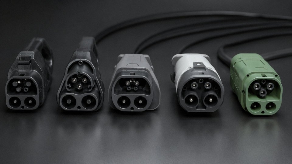
The EV charging connector landscape is fragmented by region, which creates real procurement headaches for anyone building charging infrastructure across markets. CCS2 (Combined Charging System, Type 2 base) dominates Europe and is gaining ground globally, supporting DC fast charge up to 350 kW at voltages reaching 1,000 V DC in some implementations. CCS1 uses the same DC pins but mates with a Type 1 AC base and is standard in North America and South Korea. CHAdeMO was the early fast-charge standard from Japanese manufacturers and is still installed in large numbers globally, though new deployments have slowed. GB/T 20234 is mandatory in China for both AC and DC charging and covers current ratings up to 250 A DC.
What distinguishes modern EV connectors from traditional industrial power connectors is the integration of thermal monitoring directly in the contact assembly. UL 2251, the primary North American standard for EV connectors, requires temperature sensing near the contacts with automatic charge interruption if the junction temperature exceeds safe thresholds — typically somewhere in the 85–105 °C range depending on the specification. This matters because connector degradation in EV charging is often gradual: a contact that was fine at year one develops slight oxidation or fretting by year three, resistance creeps up, and without that thermal interlock the connector quietly overheats during every fast-charge session before anyone notices.
IEC 60309 connectors are color-coded by voltage level to prevent cross-voltage mating errorsTrue
IEC 60309 defines a standardized color and keying system: yellow for 100–130 V, blue for 200–250 V, red for 380–480 V, and black for 500–750 V, combined with a clock-position key to prevent mating of connectors with different voltage ratings.
Locking, Interlocks, and Outdoor Ratings
IP54 is generally the minimum acceptable rating for outdoor power connectors in permanent installations — it handles dust ingress and splashing water. Anything near wash-down areas, marine installations, or exposed EV charging pedestals should be IP65 or IP67. Most industrial power connectors in this segment use threaded coupling rings or bayonet locks specifically to prevent live disconnection under load; breaking a 250 A contact arc without an interlock damages the contact surface rapidly and creates real arc-flash hazard. Some EV charging handles include a mechanical latch that physically prevents withdrawal until the charge controller has signaled current-off. Don’t bypass that mechanism to speed up connector swaps — the contact pitting that results will quietly raise resistance over subsequent cycles until the connector fails mid-charge.
Type 6 — PCB and Edge Connectors: Bridging Cable Assemblies to Circuit Board Architectures
PCB connectors are easy to underestimate because they’re small, cheap-looking, and buried inside enclosures where nobody sees them. That’s exactly why they cause so many field failures. Every cable harness in a machine control box, sensor node, or embedded motor drive eventually terminates somewhere on a board, and the connector at that junction is handling mechanical stress, thermal cycling, and vibration — often all at once. Get it wrong and you’re looking at intermittent faults that take hours to trace, or worse, a failed board on a production line where the connector itself is fine but it was the wrong pitch for the current load.
How PCB Connector Choice Shapes Layout, Yield, and Serviceability
The connector footprint dictates PCB real estate. A 16-way IDC header at 2.54 mm pitch occupies a fixed keep-out zone that your routing has to respect, and if you swap to a 2.0 mm variant late in the design cycle, you’re respinning the board. More practically, the mating axis — whether a connector inserts vertically (straight) or horizontally (right-angle) relative to the board — determines whether the enclosure lid can close, whether the cable bend radius is achievable, and whether a technician can actually unplug it with their fingers in a crowded DIN rail cabinet.
Assembly yield matters too. Through-hole connectors require a soldering step (wave or selective) that SMT-dominant lines often schedule separately, adding cost and handling time. That’s not a dealbreaker, but it’s a real scheduling consideration in high-mix, mid-volume production.
The Main Connector Families and Where Each One Belongs
IDC ribbon connectors — those flat grey cable plugs with the insulation displacement contacts — are the mass-termination workhorse for parallel data busses and flat ribbon jumpers inside enclosures. Standard pitch is 2.54 mm, way counts run from 10 up to 64, and termination is fast because the IDC tool cuts and seats every conductor simultaneously without stripping. The catch is strain relief: a loose or misaligned cable crimp on an IDC header develops micro-fretting at the contacts within a few hundred vibration cycles.
Molex KK series and JST-XH connectors occupy a slightly different space — wire-to-board, typically 2.5 mm pitch, with a positive friction latch that holds under moderate vibration. These are the connectors you’ll find terminating power and signal leads to small motor controllers, sensor PCBs, and anything where a few individual wires need to land on a board without a full ribbon. They’re polarized by housing key, which is genuinely useful when a board has four similar-looking headers in a row.
Card-edge and PCIe-style connectors are board-to-board and handle high-speed differential pairs. The impedance continuity through the edge fingers is critical for signal integrity; finger plating thickness (typically gold over nickel, though some cost-reduced designs use tin) directly affects contact resistance and cycle life. On a machine running automated optical inspection cameras or high-speed Ethernet to an embedded controller, this is not a place to value-engineer the plating specification.
ZIF (zero insertion force) and FFC (flat flexible cable) connectors have become increasingly common as sensor assemblies get thinner. The ZIF locking bar mechanism is delicate — technicians in the field regularly break it by opening the latch at an angle.
Pitch, Current Rating, and Where Dense Boards Fail
A 1.27 mm pitch wire-to-board contact is typically rated around 1 A continuous, versus roughly 3 A for a 2.54 mm pitch contact in the same connector family.True
Contact current rating scales with cross-section of the contact beam and the surrounding plastic's thermal mass. Halving the pitch reduces both, cutting the safe continuous current by roughly two-thirds in standard connector families.
This gap matters enormously on dense embedded boards where designers are tempted to route 24 V motor logic and 5 V sensor signals through the same miniaturized connector block to save space. The motor current — even a modest 1.5 A to 2 A — will run a 1.27 mm contact close to or beyond its thermal limit, and the failure mode is gradual: rising contact resistance, localized heating, intermittent dropout, eventually melted housing. In practice, splitting power and signal onto physically separate connectors, even at a small BOM cost, is almost always the right call.
Automated Assembly and Press-Fit for Vibration Environments
SMT-compatible versions of most wire-to-board families exist, with surface-mount tails replacing through-hole pins. These work well for pick-and-place and reflow, but they offer lower pull-out force than through-hole variants — typically 20–40% lower depending on the family and pad size. For control electronics in vibrating equipment (conveyor drives, pump skids, anything with a rotating machine nearby), compliant-pin press-fit connectors are worth the slightly higher per-piece cost. The press-fit tail deforms into the plated through-hole and creates a gas-tight joint without solder, which resists vibration-induced fatigue far better than a wave-solder fillet at the same location.
Locking, Polarization, and the Maintenance Reality
A board inside a machine controller may have eight or ten similar-looking headers in roughly the same area. During commissioning or a service visit, someone will plug a harness into the wrong connector — it’s not a question of competence, it’s a question of how long the shift has been running. Color-coded housings, physical polarization keys that physically prevent incorrect mating, and audible positive latches all reduce this risk at negligible cost. It’s worth specifying them explicitly in your connector BOM rather than leaving it to whoever’s sourcing the cheapest equivalent. The downtime from a misplugged harness during a production restart is worth far more than the few cents saved on an unkeyed generic header.
Type 7 — Waterproof and Hazardous-Location Connectors: Sealing and Explosion Protection for Extreme Environments
These are the connectors where a wrong decision doesn’t just mean downtime — it can mean a fatality, a refinery fire, or a subsea umbilical replacement that costs more than the original installation. The selection stakes here are categorically higher than anywhere else in the connector family tree.
Sealing Levels Are Not a Spectrum — They’re Engineering Constructions
Engineers sometimes treat IP ratings as a sliding scale and assume IP65 is “almost as good” as IP68. It isn’t. Each step represents a fundamentally different seal geometry and test protocol.
IP44 covers splash resistance — adequate for a sheltered outdoor junction box with no pooling risk. IP67 means the connector can be fully submerged to 1 m for 30 minutes: suitable for outdoor ground-level installations, road lighting infrastructure, and wash-down food processing environments. IP68 adds continuous submersion beyond 1 m at a depth and duration agreed between manufacturer and user — which is why you’ll see IP68 ratings quoted as “IP68 (3 m / 24 h)” on a datasheet. That parenthetical matters enormously.
Wet-mate subsea connectors are an entirely different category. These are engineered to be connected and disconnected while fully submerged, sometimes under hydraulic pressure at depth. The Souriau 8STA series, for example, is pressure-rated to 600 bar — roughly equivalent to 6,000 m depth. The mating faces are oil-filled or gel-filled to displace seawater during connection, and the contact system uses precious-metal plating to survive indefinite immersion between mate cycles. Specifying a standard IP68 connector for a subsea ROV application is not a conservative choice; it’s a failure waiting to happen.
ATEX and IECEx Zone Classification: Not a Label, a Legal Engineering Obligation
The ATEX directive (and its globally harmonized equivalent IECEx) divides explosive atmospheres into gas zones (0, 1, 2 — ordered from continuously present to occasionally present) and dust zones (20, 21, 22 — same logic for combustible dust). The connector protection concept must match the zone.
Exd — flameproof enclosure — works by containing any internal ignition inside a heavy-walled housing with precisely controlled flameproof gaps. These connectors are heavy, expensive, and genuinely appropriate for Zone 1 gas environments like pump rooms and compressor skids. Exe — increased safety — prevents ignition sources from occurring in the first place through tighter tolerances on creepage, clearance, and temperature rise. Exi, intrinsic safety, limits circuit energy below ignition threshold; M12 assemblies from Pepperl+Fuchs certified to Exi are common in Zone 0 sensor loops where no flameproof housing is practical. Mixing protection concepts across a circuit is a certification violation and, in practice, it happens more often than it should during panel modifications on aging plant.
An ATEX Zone 1 connector certified Exd can be substituted freely with an Exe connector of the same form factor.False
Exd and Exe are distinct protection concepts under IEC 60079. They are NOT interchangeable even if physically similar — each requires specific zone applicability and circuit design validation. Substitution without re-certification is a compliance breach.
For offshore chemical processing, stainless steel 316L circular connector bodies are the routine choice, not a premium upgrade. Carbon steel hardware corrodes to unusable in 18–24 months in a splash zone; 316L survives with periodic wash-down. Budget roughly 40–70% more per connector unit versus standard zinc-die-cast equivalents — a real cost, but trivial against the labor cost of replacing corroded connectors mid-shutdown.
The Connector Body Is Only Half the Seal
In my experience, most field IP and ATEX failures trace back to the cable gland, not the connector itself. The connector achieves its rated IP only when terminated with a compatible armored or unarmored gland, torqued correctly, with the right seal insert for the cable OD. A 2 mm mismatch between cable jacket diameter and gland seal bore can drop an IP68 assembly to effectively IP54 in practice. EMC glands — which add 360-degree metal braid termination — are mandatory wherever the connector specification includes screened cable for EMC compliance, and skipping them to save $3 per gland is a frequent and regrettable procurement decision.
Inspection Intervals Are Mandated, Not Optional
IEC 60079-17 specifies inspection regimes for hazardous-area electrical installations: initial inspection on commissioning, then periodic visual, close, and detailed inspections at intervals determined by environment severity. For connectors specifically, this means checking elastomer seals for compression set and cracking (silicone seals typically last 5–10 years in UV-exposed outdoor service; neoprene ages faster in ozone-heavy environments near switchgear), verifying that dust caps or blanking plugs are fitted on all unmated sockets, and confirming that no unauthorized connector substitutions have occurred. Cleaning agents matter — aggressive solvent degreasers will swell or degrade elastomer O-rings; manufacturers typically specify isopropanol or mild soap solution. It sounds mundane until a solvent-damaged O-ring fails during a winter storm and a Zone 1 junction box fills with condensate.
Connector Selection Matrix: Matching Your Application to the Right Connector Type
The seven connector families covered above don’t exist in isolation — on any real project, you’re triangulating between environment, electrical load, signal type, service life, and cost simultaneously. The table below collapses those variables into a single reference. Use it as a starting point, not a final answer; edge cases (mixed power-and-signal in one shell, ATEX zoning, unusual cable OD) will always push you back to the full datasheet.
| Connector Type | Typical Environment | IP Range | Voltage Range | Current Range | Signal Frequency | Mating Cycles | Key Standards | Dominant Industries |
|---|---|---|---|---|---|---|---|---|
| Circular (industrial) | Indoor–outdoor, vibration | IP44–IP68 | Up to 1,000 V | 10 A–400 A+ | DC to ~1 MHz | 500–5,000+ | MIL-DTL-38999, IEC 61076-2 | Defense, O&G, rail |
| Rectangular / modular | Control cabinets, dry | IP20–IP54 | Up to 690 V | 10 A–250 A | DC to signal | 500–2,000 | IEC 60603, EN 50370 | Automation, panels |
| RF coaxial | Lab, telecom, outdoor RF | IP40–IP67 | Low voltage | <1 A (signal) | 1 MHz–110 GHz | 500–1,500 | MIL-C-39012, IEC 61169 | Telecom, broadcast, test |
| Fiber optic | Data centers, field networks | IP20–IP68 | N/A (optical) | N/A | Up to 100 Gbps+ | 500–2,000 | IEC 61754, TIA-568 | IT, industrial Ethernet |
| Power (industrial/EV) | Outdoor, EV infrastructure | IP44–IP68 | Up to 1,500 V DC | 32 A–500 A+ | DC / low-freq AC | 1,000–10,000 | IEC 62196, GB/T 20234 | Energy, EV, heavy industry |
| PCB / edge | Enclosed electronics | IP20–IP40 | Up to 250 V | 0.5 A–30 A | DC to ~500 MHz | 30–500 | IEC 60512, JEDEC | Machine control, sensors |
| Waterproof / Ex-rated | Subsea, ATEX zones, chemical | IP66–IP68 | Up to 1,000 V+ | Application-dependent | DC to signal | 200–3,000 | ATEX Directive, IEC 60079 | Marine, mining, petrochemical |
Three Application Scenarios Walked Through
Outdoor wind-farm data acquisition cabinet. You’ve got a remote cabinet on a turbine nacelle — temperature swings of maybe 50 °C across seasons, constant vibration, and no realistic service window until the next scheduled maintenance rotation. Signal cables run sensor data; a few lines carry 24 V DC instrument power. The matrix points immediately to IP67 or IP68 circular connectors for field entry points, and likely fiber optic connectors for the Ethernet backbone to avoid induced noise from the generator. PCB connectors are fine inside the sealed cabinet, where the environment is controlled. Skimping on IP rating here costs you a service-truck dispatch in January.
Factory automation robot arm wiring harness. The arm cycles 80,000–100,000 times per year. Connector mating cycles matter less (the connectors themselves stay mated during operation), but the cable flex rating and connector backshell strain relief matter enormously. You’ll land on compact circular or rectangular modular connectors, IP54 typically sufficient for most automotive body shops, with positive locking to survive vibration. Any connector specified here should still be de-rated — run it at 70–80% of its rated current continuously. That de-rating alone reduces thermal stress at the contact interface and extends mean time between failures noticeably.
EV fast-charge station cable assembly. Now you’re dealing with 150–400 A continuous DC, outdoor exposure, and aggressive plug-unplug cycles from the public (easily 20–50 per day per port). IEC 62196 Type 2 or CCS connectors are mandated in most markets. Mating cycle ratings of 10,000 cycles are the floor, not a premium. IP55 minimum, IP67 preferred. Contact resistance must stay well under 5 mΩ — a corroded or worn contact at these currents generates heat fast, and thermal runaway in an EV charge connector is not an abstraction.
Contact resistance in a degraded or corroded crimp connection can exceed 50 mΩ, compared to under 5 mΩ for a properly made high-quality copper alloy crimp contact.True
This is consistent with published connector and crimp quality data from manufacturers and IEC standards; the resistance difference directly translates to I²R heating that accelerates insulation and contact degradation.
Connector De-Rating: The Rule That Gets Ignored Until It Doesn’t
Most connector datasheets specify a maximum continuous current at 20 °C ambient. Your installation probably isn’t 20 °C — a control cabinet in summer can sit at 45–50 °C internally. Running a connector at its nameplate maximum in that environment accelerates contact oxidation and can push connector body temperatures well past what the housing material is rated for. The practical rule: 70–80% of rated current for continuous-duty applications, and revisit de-rating whenever the connector is enclosed or poorly ventilated. Some manufacturers publish explicit de-rating curves; use them.
Total Cost of Ownership, Not Unit Price
A standard unrated circular connector might cost 30–50% less than the IP68, high-cycle-rated equivalent. That math inverts fast when the cheaper part fails in a subsea installation or a remote wind-farm. Unplanned downtime in process industries runs anywhere from a few hundred to several thousand dollars per hour depending on the line — one connector failure that causes four hours of downtime pays for dozens of premium connectors. Procurement teams who optimize on unit cost alone for harsh-environment applications tend to find this out the hard way, usually once.
Pre-Specification Checklist: Ten Questions Before You Commit
Answer these before finalizing any connector selection:
- What is the installation environment — indoor controlled, outdoor exposed, submerged, explosive atmosphere?
- What is the maximum continuous current, and have you applied a de-rating factor?
- What is the highest frequency or data rate the connector must pass without impedance discontinuity?
- How many mating cycles over the product’s service life, realistically?
- What termination method is available on-site — crimp, solder, IDC, screw — and is tooling accessible?
- Which standards or approvals are mandatory (ATEX, UL, CE, IEC specific parts)?
- Does the application require screen or shield continuity through the connector shell?
- Is a positive locking mechanism required — bayonet, screw coupling, push-pull — for vibration or accidental disconnection risk?
- How frequently will this connector be accessed for maintenance, and by whom?
- What is the cable outer diameter range, and does the connector’s cable entry accommodate it with the correct gland or backshell?
That last one causes more late-stage redesigns than people admit.
How Jinda Integrates Connector Compatibility Into Cable Design and Global Supply
Most cable manufacturers treat the connector as someone else’s problem. The cable ships, the connector gets sourced separately, and the assembly contractor figures out whether the two actually work together. In practice, that approach generates a predictable set of headaches — undersized conductor cross-sections that can’t accept the crimp barrel on the specified connector, jacket materials too stiff for the connector’s strain relief, shield terminations that don’t match the backshell geometry. Rework is expensive. On a 500-meter cable run going into a remote offshore installation, it’s a project-stopping problem.
Jinda’s design process starts from the termination point backward.
Cable Construction Decisions Made With the Connector in Mind
When a project specifies, say, a Harting Han-series rectangular connector on a flexible trailing cable for a port crane application, conductor stranding class matters immediately. Class 5 flexible stranding is usually acceptable for fixed installation, but Class 6 — finer wire counts, tighter bundle geometry — is what actually survives repeated flexing and still feeds cleanly into a crimp contact without wire breakout. Jinda’s YVFB and YVFR flexible control cable series are manufactured to Class 5 and Class 6 options precisely because the stranding specification changes with the termination environment.
Insulation material selection follows the same logic. XLPE holds dimensional stability under heat better than standard PVC, which matters when a connector body is running warm at continuous rated current. LSZH compounds are increasingly mandated in enclosed infrastructure — data centers, rail, marine accommodation — where the connector housing itself is often a matching LSZH-rated component. Silicone-insulated cables handle the temperature cycling in furnace and welding applications where standard thermoplastics would harden and crack at the connector entry point. Getting the insulation wall thickness right also affects how cleanly a conductor strips to the correct exposed length for the contact — a small thing that causes significant scrap at high assembly volumes.
Shielding architecture is another area where the connector termination drives the cable design. Foil shields with a drain wire suit instrumentation cables terminating into EMC gland systems. Braided shields, particularly on armored instrumentation cables, are chosen when the connector backshell requires a 360-degree braid termination for proper EMC continuity. Spiral shields offer flexibility but lower coverage; Jinda’s technical team will flag that trade-off during specification review rather than leave it for the buyer to discover after testing.
Manufacturing Scale That Supports Real Project Timelines
Five production bases across China, covering roughly 470,000 m² of manufacturing space, means Jinda runs enough parallel capacity to handle sample orders of a few hundred meters alongside bulk contracts in the tens of thousands of meters without one cannibalizing the other’s lead time. International infrastructure projects — power grid upgrades, industrial plant expansions, port terminal builds — often need qualification samples quickly and then require consistent bulk supply six to twelve months later. Both phases can be managed from a single supplier relationship, which simplifies procurement considerably.
Quality Compliance as a Connector-Termination Guarantee
Jinda’s in-house testing infrastructure covers conductor resistance measurement, insulation resistance, voltage withstand, and flame propagation — all tests that directly predict how a cable will behave once terminated. A cable that passes IEC 60332 flame propagation testing is one whose jacket compound won’t feed a fire through a connector housing penetration. Conductor resistance values within IEC specifications mean the contact resistance at the crimp joint stays within the engineered heat budget for the connector. Jinda holds IEC, GB, UL, and CE compliance across its product ranges, which matters to procurement teams managing multi-country project approvals.
Jinda cable products are exported to customers in more than 50 countriesTrue
Consistent with the company's documented international distribution and project references across Asia, the Middle East, Africa, Europe, and the Americas.
Technical Support Across the Full Specification Cycle
For international buyers, Jinda’s support model extends beyond sending a datasheet. Pre-order specification review — where Jinda’s engineering team checks that the proposed cable construction actually matches the connector type, current rating, environmental class, and mechanical requirements — catches mismatches before tooling or production starts. Customized cable drawings with annotated termination zones, showing strip lengths, shield preparation methods, and jacket dimensions relative to the connector strain relief, are available for complex assemblies. After-sales engineering support across 50-plus countries means that when a question arises at site — and on large projects, questions always arise at site — there’s a technical contact who knows the cable specification, not just a sales inbox.
Frequently Asked Questions About Cable Connector Types
What is the difference between a connector and a terminal?
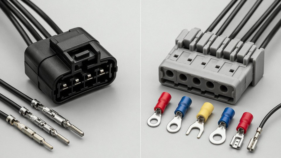
A terminal is a single-conductor end-point — a ring lug, fork terminal, bootlace ferrule, or pin — crimped or clamped onto one conductor and attached to one stud, lug, or cage clamp. It does not mate with anything; it just secures a wire. A connector, by contrast, is a multi-way housing system: it contains multiple contacts, aligns them mechanically, and allows repeated mating and unmating between two cable assemblies or between a cable and a piece of equipment. That repeated connect/disconnect capability is the defining feature. On a control panel terminal block, you’re working with terminals. On a machine’s quick-disconnect cable harness, you’re working with a connector. Mixing up the vocabulary isn’t just pedantic — specifying “terminals” when you actually need a field-replaceable multi-pin connector leads to designs that require rewiring during maintenance instead of a 5-second unplug.
Can I use an IP67-rated connector in a Zone 1 hazardous area?
No — or at least, not on its own. IP rating tells you about ingress protection: dust, water, submersion depth. It says absolutely nothing about whether the connector can generate an arc, spark, or surface temperature capable of igniting a flammable atmosphere. ATEX (Europe) and IECEx (international) certifications address ignition risk through separate engineering requirements — enclosure construction, surface temperature limits, and in many cases intrinsically safe circuit design. A connector used in Zone 1 typically needs both: IP66 or IP67 for environmental sealing and a valid ATEX/IECEx Ex d, Ex e, or Ex i certification for the explosion protection mode. Treat them as two independent checklists, not overlapping ones.
IP67 rating alone qualifies a connector for use in ATEX Zone 1 hazardous areasFalse
IP ratings only address dust and water ingress. ATEX/IECEx certification is a completely separate requirement governing ignition risk and is mandatory for hazardous area use regardless of IP rating.
How do I know what connector fits my existing cable outer diameter?
Measure the cable OD with calipers — not a ruler, not your fingers. Every connector cable gland, clamp, or strain-relief entry has a listed clamping range, usually something like 6–10 mm or 8–14 mm. If your cable OD lands right at the edge of that range, you’re in trouble: too loose and the strain relief won’t grip, meaning flexing loads transfer directly to the solder or crimp contacts. In that situation, a heat-shrink boot built up over the jacket can effectively increase the OD to sit in the center of the clamp range. Overmolded strain relief is cleaner still if you’re producing in volume. The worst habit I see in the field is someone forcing a cable that’s a couple of millimeters too slim into a gland and relying on the locknut torque to compensate. It doesn’t work long-term.
What causes connector contact failure, and how can I prevent it?
Four failure modes dominate. Fretting corrosion happens when vibration produces micro-movement between mated contacts, grinding through the plating and generating resistive oxide debris — gold plating over nickel significantly reduces this. Galvanic corrosion occurs when dissimilar metals meet in the presence of moisture; an aluminum-shell connector with unplated copper contacts in a coastal environment is a predictable failure. Over-crimping crushes conductor strands and creates stress fracture points that open up under thermal cycling. Thermal cycling fatigue itself — daily heat-up and cool-down in a motor junction box, for instance — works contact interfaces loose over months.
Prevention is straightforward in principle: match plating to the environment (gold for low-signal dry contacts, tin for power contacts in clean environments, silver for high-current with good sealing), use the manufacturer’s specified crimp tooling and die, verify crimp pull-force against spec on the first batch, and build quarterly visual inspection into the maintenance schedule for any connector in a vibrating or thermally cycling application. Contact resistance is your early-warning metric — a high-quality crimp contact should measure under roughly 5 mΩ; anything trending above 20–30 mΩ warrants investigation before it becomes a thermal event.
Is there a universal connector standard I can use across all my equipment?
There isn’t, and anyone selling you one is oversimplifying. Power, signal, data, and environmental requirements diverge too sharply for any single connector family to cover everything safely. That said, the M12 circular connector comes closer than anything else for industrial sensor and fieldbus applications — IEC 61076-2-101 defines it globally, and you’ll find M12 A-coding, D-coding, and X-coding covering sensors, PROFIBUS, and 10 Gbps Ethernet respectively on most modern factory floors. For anything involving higher current, RF signal integrity, or fiber optics, you’re back to application-specific families. The practical approach is to standardize within application categories — one circular series for all field instruments, one rectangular series for all panel wiring — rather than chasing a single universal solution.
How does connector type affect cable bend radius requirements?
The cable datasheet gives you a minimum bend radius for the cable body, but that number becomes almost irrelevant right at the termination zone. A rigid metal-shell connector — MIL-DTL-38999 circular, N-type RF, or a steel-armored industrial connector — creates a hard fixed point. Any flex in service concentrates at the cable exit, and if the strain relief isn’t correctly designed for the expected flex angle and cycle count, fatigue failure initiates there, not at the mid-span of the cable. The strain relief geometry — its length, hardness, and whether it’s a simple clamp boot or a tapered overmold — determines how bending load is distributed away from the termination. For cables in continuous flex applications (robotic arms, cable track systems), a straight-exit connector is usually the wrong choice; a right-angle or swivel-backshell version distributes the bend properly. Specifying the cable bend radius without also specifying the strain relief design is half a specification.