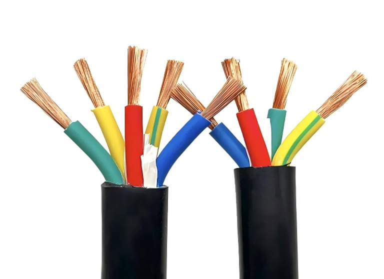
Someone buries a cable without thinking too hard about it — wrong depth, no bedding sand, no warning tape — and it works fine until a groundworker’s bucket tooth finds it three years later, or a summer dry spell pushes soil resistivity high enough that the cable quietly thermally degrades under sustained load. The repair bill is rarely just the cable: it’s excavation, traffic management if it crosses a driveway, potential damage claims, and unplanned downtime that ripples back through whatever the circuit was feeding. Getting direct burial right the first time is genuinely cheaper than getting it wrong once.
Yes, you can bury an armoured cable directly in the ground, but only if you meet specific depth, bedding, and route-marking requirements. Under BS 7671 and IEC 60364 guidance, minimum cover is 450 mm under footpaths, 600 mm under open ground, and 900 mm under roads or driveways. The cable must also be suitable for the soil conditions — thermal resistivity, mechanical risk, and chemical environment all affect whether SWA alone is sufficient or whether ducting is needed.
What most installation guides skip over is the gap between “technically permitted” and “actually safe for the next 30 years.” Depth is only the starting point. The soil your cable sits in is a thermal environment that changes with the seasons, a mechanical environment that shifts with ground movement and third-party work, and sometimes a corrosive one depending on what else is buried nearby or what the ground chemistry looks like. Each of those factors has a direct line to either a fault or a derated circuit that never quite delivers what the design assumed.
How Armoured Cable Construction Determines Its Suitability for Direct Burial
The cable itself earns the right to be buried — or it doesn’t. Understanding why means working from the conductor outward, because every layer was designed with a specific threat in mind, and underground conditions are not forgiving when one layer underperforms.
The Layer Stack and What Each One Does Underground
Start at the centre: the conductor, copper or aluminium, sized for current and voltage drop. Aluminium runs lighter and cheaper per ampere-metre, but it’s more sensitive to mechanical nicking during installation — a detail that matters on a rocky pull. Immediately outside the conductor on medium-voltage designs is a conductor screen, a semi-conductive layer that smooths the electric field gradient and prevents localised stress concentrations that would eventually punch through insulation.
The insulation itself — XLPE or PVC — is where voltage is actually held off. XLPE handles higher operating temperatures (90°C continuous versus 70°C for PVC), which translates directly to higher current-carrying capacity in a trench where heat dissipation is limited by soil thermal resistivity. That resistivity can swing from roughly 0.5 K·m/W in wet clay to around 3.0 K·m/W in dry sandy backfill, and in the worst case that difference alone can force a 30–40% derating of the cable’s rated current. It’s not an abstract datasheet footnote; it’s the reason a cable that was perfectly sized on paper overheats in a summer drought.
On MV cables (roughly 6–35 kV), a core screen sits outside the insulation — another semi-conductive layer, plus a metallic earth screen (copper tape or wires) that provides fault current return path and shields the cable from external electric fields. This metallic screen needs a deliberate earthing strategy at installation: earth one end only to prevent circulating currents, or both ends with appropriate cross-bonding on longer runs. Get that wrong and you generate continuous heating losses even at normal load.
Inside the outer armour: fillers (usually thermoplastic compounds or textile) pack the interstices between cores, keeping the assembly round and preventing moisture tracking along air channels. The inner sheath — sometimes called bedding — cushions the armour wires against the cores and provides a secondary moisture barrier.
SWA vs. STA vs. AWA: The Choice Is Not Random
Steel Wire Armoured (SWA) cable uses helically applied steel wires. That construction resists longitudinal tensile stress — critical when a cable is pulled through conduit, laid on a slope, or subjected to soil settlement over time. Pull tension limits for SWA are typically in the range of 50–70 N/mm² on the conductor cross-section; exceed that and armour wires deform, which then bites into the bedding and eventually stresses the insulation. On sloped ground or through rocky terrain, SWA is usually the right call.
Steel Tape Armoured (STA) cable wraps flat steel tapes in overlapping layers. It handles radial crush well — useful in stable, flat runs — but offers noticeably less tensile strength. Avoid STA anywhere with significant grade changes or where ground movement is expected.
For single-core AC cables, aluminium wire armour (AWA) eliminates the induced circulating current losses that a closed steel armour loop would generate.True
Steel armour forms a closed magnetic circuit around a single-core AC conductor. The alternating magnetic field induces a voltage around that loop, driving circulating currents that produce real I²R losses and heat. Aluminium is non-ferromagnetic, so it does not form an effective magnetic circuit, suppressing these induced currents. In practice this can recover efficiency losses that would otherwise reach several percent of transmitted power on heavily loaded single-core runs.
On long, heavily loaded single-core MV runs, switching from SWA to AWA can recover efficiency losses in the range of 2–5% of transmitted power, depending on conductor size, load factor, and armour cross-section. Not trivial.
Outer Sheath Material Is Not Just a Commercial Decision
PVC outer sheaths are cost-effective and handle most neutral soils, UV exposure during surface runs, and incidental moisture without complaint. In contaminated ground — industrial sites, old landfill, petrochemical zones, anywhere soil pH drops below about 5 or climbs above 9 — PVC can soften or embrittle over time. HDPE sheaths tolerate aggressive chemistry substantially better and are worth the modest premium on any site with known contamination.
LSZH (low-smoke zero-halogen) outer sheaths make more sense where cables route through tunnels, cable culverts, or dense urban cable corridors where a fire event would trap combustion gases. They’re not mechanically superior underground; the value is in what they don’t release when they burn.
What Armour Does Not Do
This is where assumptions become expensive. Armour is a mechanical layer. It does not stop sustained electrochemical attack. Stray DC currents from nearby electrified rail, cathodic protection systems, or even poorly earthed welding equipment can drive galvanic corrosion through a steel armour progressively — without any visible surface symptom until a fault develops. Acidic or highly alkaline soils attack steel wire directly; the protective effect of the outer sheath is the only real barrier, and if that sheath is nicked during laying, the armour underneath begins corroding from that point forward. Prolonged waterlogging without a verified watertight outer sheath is similarly problematic — not an immediate failure, but a slow degradation that shows up five to twelve years later as insulation resistance drift.
Knowing the layer stack means knowing which layer you’re actually relying on for each threat. That’s the foundation of a burial decision that holds up over a 30-year service life.
Soil Assessment Before You Dig: The Step Most Installers Skip
Most cable failures in direct-burial installations aren’t caused by choosing the wrong cable — they’re caused by installing the right cable into ground that was never assessed. A contractor who skips soil testing is essentially guessing, and in my experience that guess costs money eventually, whether that’s a derated circuit tripping thermal protection six months after commissioning, or corroded armour discovered during a trench reopened for an unrelated reason.
Thermal Resistivity: The Number That Controls Your Ampacity
Thermal resistivity (ρ, expressed in K·m/W) describes how well soil conducts heat away from a buried cable. It is, without question, the single most important soil parameter for cable sizing underground — more important than burial depth within normal ranges, more important than backfill compaction.
Wet clay sits around 0.5–0.8 K·m/W: it conducts heat well and is broadly benign for ampacity. Loam runs roughly 1.0–1.2 K·m/W, which is the baseline assumption most IEC 60287 ampacity tables use. Dry sand is where things go wrong — 2.5–3.0 K·m/W, and in drought conditions some sandy soils get worse. At that level you can expect a derating of 25–40% against the tabulated current capacity, depending on cable OD, burial depth, and whether multiple circuits share the same trench. A 95 mm² SWA circuit derated by 30% in poor soil may carry less current than a 70 mm² circuit in good soil. Cable undersizing isn’t always the designer’s error; sometimes the soil specification was just never done.
The IEC 60287 derating procedure requires you to know your actual site ρ value, not a textbook estimate. Thermal resistivity probes are cheap to hire, and the test itself takes under an hour. There is no good reason to skip it on any cable circuit above, say, 50 A.
Chemical Aggressiveness and pH
Soil pH below 5.0 or above 9.0 is directly corrosive to steel wire armour and to standard PVC outer sheaths. Acid soils hydrolyse the plasticisers in PVC over years; highly alkaline ground — common near old concrete rubble fills or lime-stabilised subgrade — attacks the armour coating. Sulfate content above roughly 400 mg/kg accelerates metallic degradation further, and this matters especially on sites with made ground, near old industrial works, or anywhere fill material origin is uncertain.
If lab pH or sulfate results come back outside safe ranges, the cable specification needs to change before a single metre of trench is opened. Minimum response: an HDPE outer sheath instead of PVC. In severely contaminated ground, bitumen-wrapped armour or a fully enclosed HDPE duct system is the more defensible choice. Reopening a trench to replace a corroded cable is not a small job.
Soil pH below 5.0 accelerates corrosion of steel wire armour in direct-buried cablesTrue
Acidic soils accelerate electrochemical corrosion of ferrous metals; BS 8010 and IEC 60364-5-52 both reference soil chemical aggressiveness as a factor in cable installation design and sheath material selection.
Stray Current and Galvanic Risk
Any site within roughly 500 m of a DC traction system — railway, tramway, light rail — carries stray current risk. DC leaks from return rails into the earth and back to the source through any conductive path it can find, including steel armour. The resulting galvanic corrosion can eat through armour wires in under ten years on a bad site. The same risk exists near impressed-current cathodic protection systems protecting adjacent pipework, and near grounded DC industrial equipment like rectifiers.
Mitigation options aren’t one-size-fits-all. Sacrificial zinc or magnesium anodes bonded to the armour work in low-risk situations. Insulating joints that interrupt the armour’s electrical continuity along the route are more effective where stray current density is higher. On particularly aggressive sites, an impressed current cathodic protection system covering the cable route is warranted — expensive, but far cheaper than replacing a 300 m buried circuit. The key is identifying the risk before installation, because retrofitting corrosion protection underground is painful.
Ground Movement and Mechanical Stability
Expansive clays — high plasticity index, typically above PI 35 — move seasonally. Cables buried in shrink-swell clay experience lateral and vertical displacement as moisture content changes, which over several cycles concentrates mechanical stress at any fixed point: a duct entry, a joint bay, a buried draw-pit. Rocky ground creates a different problem: point loading from angular stone fragments against the cable OD, particularly during installation pull-in.
In expansive clay, concrete tile protection above the cable is a minimum, and a flexible bedding sand surround of at least 75 mm all around matters more than the tile itself. In rocky ground, split-duct or continuous smooth-bore HDPE duct is usually the right call even when direct burial would technically be permitted — the armour can handle a lot, but repeated abrasion against a sharp granite edge for two decades is a different thing.
A Working Site Assessment Checklist
Before mobilising an excavator, a competent installation team should have completed the following:
- Visual inspection of the trench route for signs of fill material, demolition rubble, or unusual discolouration suggesting contamination
- Laboratory thermal resistivity measurement along the cable route, with at least one sample per 100 m on variable ground
- Laboratory soil pH and sulfate content test on samples from proposed burial depth
- Review of historical Ordnance Survey or equivalent mapping to identify former industrial land use, landfill, or made-up ground
- Consultation of utility records and local authority strike maps for existing buried services
- Assessment of proximity to DC traction, cathodic protection systems, or industrial DC sources
These results feed directly into which cable specification is ordered, what bedding material is used, whether conduit adds enough value to justify the cost, and what the final burial depth needs to be. None of it is difficult. It just requires doing the work before the cable reel is on site rather than after the trench is already open.
Burial Depth, Separation, and Route Planning: The Dimensional Rules That Protect Cables for Decades
Depth requirements exist for two distinct reasons that most installers conflate into one: mechanical protection and thermal management. Treating them as a single concern — “just go deep enough” — misses half the engineering.
Minimum Burial Depths by Surface Type
The numbers below come from BS 7671 (18th Edition), IEC 60364-5-52, and NEC 300.5. They are minimums, not targets, and real conditions often push you deeper.
| Surface type | BS 7671 / IEC 60364 minimum | NEC 300.5 equivalent | Primary hazard being controlled |
|---|---|---|---|
| Footpaths, light foot traffic | 450 mm | 300 mm (GFCI protected) | Spade or garden fork strike |
| General open ground | 600 mm | 600 mm | Landscaping, shallow service trenches |
| Roads and driveways | 900 mm | 600 mm in conduit | Vehicle loading, road maintenance |
| Agricultural land (deep plough risk) | 1200 mm | Site-specific | Subsoil ploughing to 600–900 mm depth |
The NEC figures look more permissive partly because they assume conduit in many contexts. Direct-buried SWA under a UK road at 600 mm instead of 900 mm is a non-compliant installation — and if a cable strike injures a contractor five years later, that drawing becomes evidence in a liability claim.
The Thermal Argument for Depth
Here is where the physics actually bite you. Shallow burial in summer means the cable sits in soil that has absorbed radiant heat from the surface. At 300 mm depth under open ground in a warm climate, soil ambient temperature can run 35–40°C in mid-summer. At 600 mm it is closer to 25°C, give or take depending on soil type and shade cover.
Run the IEC 60287 derating: a 95 mm² SWA cable rated at, say, 210 A continuous in 25°C soil with a thermal resistivity of 1.2 K·m/W derated to roughly 170–175 A in 35°C soil — a reduction of 17–20% before you have even accounted for grouping factors. If your design assumed 200 A load at the cable boundary, that 300 mm shortcut just put you into chronic overtemperature. Insulation degrades logarithmically with temperature; that mistake might not trip a breaker for years, but it will halve the cable’s service life quietly.
Cable Spacing and Grouping Derating
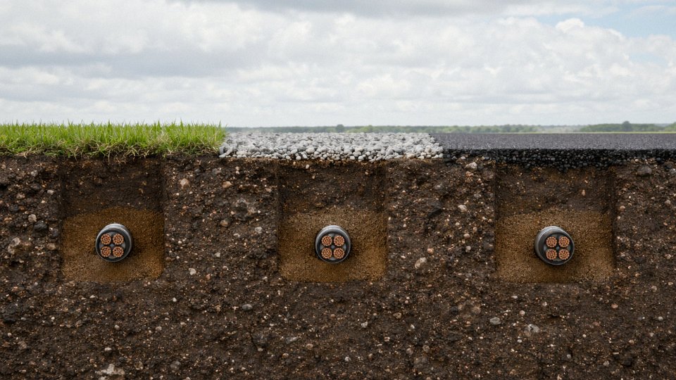
For multi-cable runs, the IEC 60287 grouping derating factor drops to around 0.6 for six cables laid touching in a flat formation. Space them at 70 mm centre-to-centre — the standard minimum for same-circuit cables — and the factor recovers to roughly 0.75–0.80. That difference can mean the gap between using 95 mm² and 120 mm² conductors across a 200 m run. At current copper pricing, that sizing decision is worth calculating properly rather than guessing.
Parallel circuits feeding the same load need even more thought. Mutual heating between circuits is cumulative; if you have three parallel feeders in a tight trench, treat them as a group and apply derating before you finalise conductor size.
Separation from Other Utilities
The rule of thumb heard on site — “keep it away from the gas pipe” — is correct but vague. The actual figures matter when space is tight in a congested service corridor:
- 300 mm minimum from gas distribution pipes
- 500 mm from potable water mains (freeze/thaw cycling near water pipes causes soil movement)
- 600 mm from telecom cables (induced interference is secondary; the real issue is preventing accidental joint damage during telecom maintenance)
Marker tape — orange for power, 150 to 300 mm above the cable depending on regional practice — is not optional decoration. Third-party strikes are the leading cause of unplanned cable outages in urban infrastructure. A mechanical contractor with a mini-excavator will not be checking your as-built drawings. The tape buys a few seconds of warning; those seconds matter.
BS 7671 requires marker tape to be installed above direct-buried cables as a mandatory precaution against third-party excavation damageTrue
BS 7671 Regulation 522.8.10 requires that cables buried in the ground be marked by cable covers or marker tape to alert future excavators, making marker tape a code-specified requirement, not merely best practice.
Route Planning: The Work Nobody Wants to Do Until Something Goes Wrong
Shortest practical route does not mean shortest route. It means routing that avoids areas scheduled for future development, stays clear of known contamination zones, allows access at joints and terminations without full excavation, and gets documented properly.
GPS-referenced as-built drawings are not bureaucracy — they are the thing that prevents your maintenance crew from spending three days locating a fault in a 400 m run six years from now. Cable route markers at grade level (the small yellow posts, or flush plaques in paved areas) are cheap. Relocating an unmarked cable that nobody can find is not.
Trench-Free Road Crossings
For road crossings, horizontal directional drilling (HDD) or thrust boring is almost always worth the extra cost on any crossing over roughly 6–8 m. Install HDPE duct — 100 mm diameter minimum for a single SWA, typically — with a draw rope left inside. That rope is what allows cable replacement without re-boring a decade later when the road is fully loaded with traffic.
HDD costs vary considerably with soil conditions and crossing length, but for a standard two-lane road crossing of 10–15 m, the premium over open-cut is usually recovered the first time you avoid a road closure permit. Compacted granular backfill under roadways is also notoriously difficult to re-compact to the original specification, making re-excavation a headache nobody wants twice.
Trench Preparation, Bedding, and Backfill: Why the Ground Around the Cable Matters As Much As the Cable Itself
Most cable failures attributed to “burial” aren’t really cable failures. They’re trench failures. The cable itself was fine; the ground around it moved, compressed unevenly, or introduced point loads that the armour was never designed to resist continuously. Getting the trench right is arguably more important than cable selection once you’ve confirmed the correct cable type.
Trench Dimensions and Wall Stability
Minimum trench width for a single cable run is 300 mm — not because the cable needs that much space, but because you need working room to lay bedding material properly and verify it’s seated evenly. Add roughly 100 mm for each additional cable in the same trench. Where you have, say, four cables running in parallel, a 600–650 mm trench width is realistic minimum.
Trench walls matter more than most site supervisors acknowledge. Rocky spoil left proud on a wall face, a protruding root, a sharp flint — any of these creates a point load on the outer sheath that doesn’t show up at commissioning and won’t show up for months, until ground movement or frost cycles push that object directly into the cable. Dress the walls before laying. This takes twenty minutes; ignoring it can mean excavating 50 m of trench two years later to find one penetration point.
Bedding Layer: The Load Distribution Platform
Lay a minimum 75 mm bed of fine sand or selected granular fill before the cable goes in. “Fine sand” means passing a 5 mm sieve, and it genuinely must be free of sharp particles — quarry fines with angular edges are not an acceptable substitute for washed sharp sand, regardless of what a groundworks crew might tell you. If there’s any doubt about the material quality on site, a quick sieve analysis takes under an hour and removes the ambiguity.
This layer does two things. It distributes load across the cable’s circumference rather than allowing it to bear on isolated high points in the trench bottom. It also creates reasonably uniform thermal contact with the cable jacket, which matters directly for current-carrying capacity — an air void under a cable in high-load service is essentially a local insulator and can cause localised heating over months or years.
Laying the Cable Without Inducing Twist
Unroll cable directly from the drum. Never figure-eight it on the ground before feeding into the trench — figure-eight coiling introduces opposing twist segments that don’t cancel out cleanly and leave residual torsional stress locked into the armour wires. Check drum flanges for damage before pulling begins; a cracked or deformed flange can grip and kink the cable during unspooling in a way that’s difficult to detect until you’re looking at the armour under a magnifier.
Maintain minimum bending radius throughout the run. For SWA cables this is typically 8–12 times the overall cable diameter, depending on conductor cross-section and construction — smaller conductors with thicker relative armour sit toward the tighter end of that range. Corners are where this gets violated most often on site. Mark your corner points before the drum starts turning.
Figure-eight coiling of armoured cable before burial induces permanent torsional stress in the armour layer.True
Reversing the coil direction mid-lay creates opposing twist that doesn't self-cancel; the residual stress concentrates at transition points and can accelerate armour wire fatigue under cyclic loading underground.
Cover Layer, Warning Tile, and Marker Tape
Once the cable is laid, place a minimum 75 mm of the same fine sand or selected fill over it before any backfill. This is not optional and it’s not interchangeable with native spoil. Sharp stones in backfill dropped directly onto a cable are responsible for a significant share of the premature failures I’ve seen pulled out of the ground on infrastructure projects.
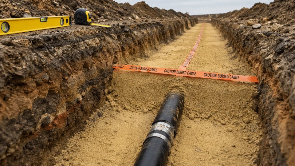
At 150 mm above the top of the cable, lay a continuous warning tile — ceramic or concrete-backed — or at minimum a continuous run of warning tape clearly marked with the cable voltage level. The 150 mm spacing is deliberate: shallow enough that a spade or mini-excavator hits the warning before reaching the cable.
Backfill Compaction
Backfill in 150 mm compacted layers using a plate compactor. Don’t run the plate directly over the cable until you have at least 300 mm of compacted fill above it; before that depth, the vibration and direct pressure can deform the armour. Target 95% Proctor density throughout — loose backfill that settles over winter allows surface water to migrate downward along the trench line toward the cable, particularly where ground level is higher than the surrounding area.
Thermal Backfill for High-Load Installations
On high-load circuits — main feeders, EV charging infrastructure, industrial supply cables running near capacity — native soil thermal resistivity can quietly reduce current-carrying capacity by 30–40% compared to rated conditions if the soil is dry sand or similar poor-conductivity material. In these cases, thermal backfill is worth serious consideration.
Controlled low-strength material (CLSM) or specialist thermal sand with resistivity below 1.0 K·m/W can be placed around the cable in place of native fill, typically extending 150–300 mm around the cable envelope. Cost premium over standard backfill is roughly 3–8 times the material cost per linear metre, which sounds significant until you calculate what under-rated conductor sizing or a future cable replacement excavation actually costs on a busy site. For infrastructure projects handling sustained high loads, thermal backfill often pays back within the first few years through avoided derating and the ability to use a smaller conductor cross-section at design stage.
Jointing, Termination, and Earthing Underground: The Failure Points That Installers Underestimate
Walk through enough post-fault investigations on buried LV and MV systems and a pattern becomes impossible to ignore: somewhere between 60% and 70% of buried cable failures originate at a joint or termination, not somewhere along the clean cable run between them. The cable manufacturer gets blamed. The cable is usually fine. It’s the jointing that failed — often slowly, over months or years, as moisture crept into a kit that wasn’t rated for ground burial, or as an armour earth connection corroded to nothing inside a flooded joint pit.
That statistic should reframe how you allocate installation time and budget. Spending two hours on meticulous bedding and backfill while rushing a joint in fading daylight is exactly the wrong trade-off.
Approximately 60–70% of buried cable failures originate at joints or terminations rather than along the cable run itself.True
This figure is consistent with findings from network operator failure analysis reports and is cited in IET guidance on cable installation and jointing practice. Root causes include moisture ingress, inadequate armour bonding, and incorrect stress control at MV joints.
LV SWA Joint Kits: Indoor-Rated Versus Direct-Burial Rated
This distinction trips up procurement more often than it should. A heat-shrink straight joint kit designed for above-ground or panel installation will often look nearly identical to a direct-burial kit on the shelf. The critical difference is the outer mould: below-ground kits require a resin-filled encapsulation — polyurethane or epoxy resin injected into a rigid outer shell — that mechanically excludes water even under sustained hydrostatic pressure. Without it, you’re relying on heat-shrink alone, and ground moisture will eventually find the interface.
Cold-shrink kits have become the practical preference for in-trench jointing, and for good reason. No open flame or heat gun in a confined excavation, no risk of charring bedding sand or over-heating an adjacent service. The cold-shrink silicone sleeve is pre-stretched on a removable core; you pull a tab and it contracts onto the cable. In cold weather — below about 5°C — cold-shrink kits can be sluggish, so factor that into winter installation schedules. Either system, heat-shrink or cold-shrink, must be specified explicitly for direct-burial service. “Outdoor rated” is not the same thing.
MV Joints: Partial Discharge Is Not a Downstream Problem
At medium voltage, the consequences of a poorly made joint are faster and more severe. The semi-conductive screen over the insulation — the layer that smooths the electric field geometry — must be re-established continuously and correctly across the joint. Miss this, leave a geometric discontinuity or an air void at the screen cut-back point, and you’ve created a partial discharge site. PD degrades insulation incrementally but relentlessly. A cable system that passes commissioning testing can still fail within two to five years if the MV joint was assembled without proper stress control geometry. Prefabricated cold-shrink MV joint kits with factory-controlled stress cone geometry are worth the extra cost over field-built tape joints for exactly this reason.
Armour Bonding and the Circulating Current Question
Armour continuity is not optional. The steel wire or tape armour is both mechanical protection and a fault current return path, and it needs to be bonded to the earthing system at each end of the cable run. For LV SWA, both-ends earthing is standard and straightforward — bond the armour at the supply end and at the load end, connect both to the earthing conductor. The practical complication arises with longer single-core LV cables or single-core MV cables: bonding the screen or armour at both ends creates a closed loop, and any imbalance in the magnetic field induces circulating currents that heat the armour and waste energy. Circulating current losses in a long single-core run bonded at both ends can reach 10–20% of conductor losses depending on spacing and current magnitude. Single-point earthing (bonding at one end only, with a voltage-limiting device at the other) breaks the loop. The choice between the two strategies depends on cable length, current level, and whether induced voltages at the un-bonded end can be kept within safe limits — typically below 25 V to 65 V depending on the standard and accessibility of the location.
Joint Pit Construction
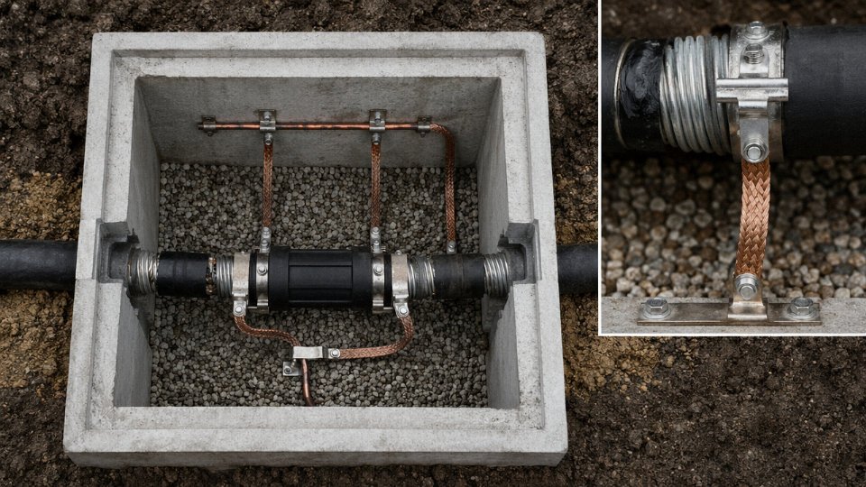
Permanent buried joints should not be buried blind. A properly constructed joint pit — sand-filled internally, with a concrete surround and a surface access cover — protects the joint mechanically, allows inspection, and provides drainage. Minimum internal dimensions of roughly 600 × 600 × 600 mm are widely cited in network operator standards; for multiple-cable joints or large-cross-section MV cables, you’ll need more room than that. A sump or drainage connection at the pit base is not a luxury: in clay soils, even well-drained trenches accumulate water seasonally, and a flooded joint pit accelerates corrosion of armour terminations and earth connectors faster than most installers expect.
Testing Before the Trench Closes
Once the backfill goes in, your window for non-destructive diagnosis narrows dramatically. Before burial, run an insulation resistance test at 500 V DC for lower-voltage cables or 1 kV DC for cables rated above 1 kV — record the result as a baseline. After jointing but before backfill, perform an HV withstand test per the relevant standard (typically at 3–4 kV DC for LV cables or as specified for MV). Check armour continuity with a low-resistance measurement. Document everything: cable drum numbers, joint kit batch numbers, IR values, test voltages, and the name of the jointer. Those records are your evidence base if a fault develops later and liability becomes a question.
Rushing this sequence because the concrete pour is scheduled for tomorrow morning is how projects end up with an uninvestigated fault three years later and no baseline data to work from.
Mechanical Protection, Marker Systems, and Third-Party Strike Prevention
Third-party excavation damage — a digger bucket or a hand-held breaker hitting a buried cable that nobody knew was there — accounts for a significant share of unplanned outages on industrial and infrastructure sites. The cable itself may be perfectly installed, joints intact, depth correct. None of that matters once a machine strikes it. So the protection hierarchy doesn’t end when the trench closes; it starts a new phase.
The Layered Protection Hierarchy
Armour is the first line. SWA or STA construction handles incidental scraping, minor point loads, and rodent damage reasonably well. It is not designed to absorb a direct hit from a mechanical excavator. For that, you need a second physical barrier.
In high-risk zones — road crossings, areas with future development planned, congested utility corridors — draw the cable through a split-duct or HDPE conduit before backfilling. The conduit adds mechanical standoff and, usefully, makes future cable replacement or partial rerouting possible without full excavation.
Concrete protective tiles are a different class of protection entirely, and the two are frequently confused. A concrete tile sits above the cable and absorbs the initial impact of a dig — it is a physical strike barrier. Minimum specification is 600 mm wide, 50 mm thick, positioned so that the top of the tile is at least 300 mm above the cable. For multi-cable routes or road crossings, pre-cast concrete cable protection covers (channel-shaped sections) are more practical and give consistent positioning across a long run. Neither of these is interchangeable with marker tape, which is a warning device. Marker tape does not stop anything.
Marker Tape — Warning, Not Protection
Marker tape requirements are often under-specified on procurement documents. Minimum width is 150 mm. Colour for electrical services is yellow with black text. The legend should be continuous along the full length — “CAUTION ELECTRIC CABLE BELOW” or a recognised local equivalent — not printed at intervals where it could be missed in a partial trench. The material should be UV-stable polyethylene; cheap alternatives become brittle within a couple of seasons if they are ever exposed.
Place the tape 150–300 mm above the cable, not immediately on top of it. The point is to give a worker with a hand tool a warning before the blade gets close. If the tape is flush against the cable jacket, it provides almost no reaction time.
Detectable marker tape with an embedded metallic strip is worth specifying on any project where the route will need locating in the future. A cable avoidance tool (CAT) can pick up the signal from a passive metallic strip without needing the cable itself to be energised or signal-injected. On long rural runs or in dense industrial yards where the original installation crew won’t be around in fifteen years, this is genuinely useful.
Standard yellow marker tape acts as a physical protection barrier against excavation damage.False
Marker tape is a warning device only. It alerts excavators to the presence of a cable but provides no mechanical protection against a strike. Physical protection requires concrete tiles, protective covers, or conduit.
Above-Ground Route Markers
Route markers above ground are essential at every direction change, road crossing, and joint position. Cast-iron or HDPE marker posts are both acceptable; the post must display the voltage class, cable owner identification, and an emergency contact number. In practice, the emergency contact is the detail most often missing or out of date — worth checking during any project handover review.
CAT, Genny, and the GPS As-Built Problem
A cable avoidance tool (CAT) used with a signal generator (genny) is the standard pre-excavation survey method. The genny clips onto the cable or an earthed surface conductor and injects a traceable signal; the CAT receiver lets the operator walk the route and confirm depth and position. The limitation that rarely gets mentioned explicitly: this only works if the cable route has been accurately recorded and the asset registered. A cable buried ten years ago on a site that has changed hands twice, with paper drawings long gone, is essentially invisible to CAT unless detectable tape or a metallic marker was installed.
This is the practical argument for GPS as-built drawings on every project. Post-installation GPS survey of the route, logged to a coordinate system that survives building changes and ownership transfers, is not expensive relative to the total project cost. It is almost always skipped on smaller industrial or commercial installations.
Utility Notification Systems
Dial-before-you-dig programs exist precisely because the as-built records problem is widespread. In the USA, 811 is the national one-call system. Australia operates Dial Before You Dig (DBYD). The UK uses LSBUD (Lines and Structures Below Underground). These systems only work if cable owners register their routes in the first place. An unregistered cable returns no data on a pre-dig enquiry, and the excavator proceeds assuming the ground is clear.
Route registration through the relevant national utility notification system should be a formal deliverable in the project handover checklist — not optional, not deferred. On international projects supplied through manufacturers like Jinda, the technical handover package should include route records in a format directly suitable for submission to the local notification authority. That one step, consistently applied, closes a failure mode that no amount of quality cable installation can compensate for.
Current-Carrying Capacity Derating for Direct-Buried Cables: Getting the Sizing Right Underground
Tabulated cable ratings look reassuringly precise in IEC 60502 or BS 7671 Appendix 4. They are not design values — they are reference values. Every published figure assumes a specific set of conditions that, in practice, almost never all apply simultaneously: soil thermal resistivity of 1.0 K·m/W, installation depth of 0.8 m, ground temperature of 20°C, a single isolated cable. Change any one of those, and the number changes. Change several at once, which is the normal situation on a real project, and you can be looking at a cable that’s genuinely undersized before a single amp has flowed.
Why Reference Conditions Are Rarely Your Conditions
Soil resistivity alone swings from roughly 0.5 K·m/W in wet clay to around 3.0 K·m/W in dry sand or gravel — and that 3.0 figure is not a worst case you can ignore. Installations in coastal industrial zones, areas with good drainage, or sites next to compressed-air piping or heat-generating adjacent services can sit in that upper range. At 3.0 K·m/W, current-carrying capacity derating relative to the 1.0 K·m/W reference runs 30–40%, depending on conductor size and construction. That’s not a rounding error. That’s the difference between a cable running comfortably at design load and one slowly cooking in the ground.
Depth adds another correction. The standard reference depth is 0.8 m, but road crossings typically go to 900 mm or deeper, and heat dissipation decreases as you go deeper — the ground around a deeply buried cable acts as better insulation. Ground temperature is equally project-specific; in parts of the Middle East and South Asia, undisturbed ground at 500 mm depth can reach 30–35°C in summer, not 20°C.
Walking Through the Derating Methodology
Take a 95 mm² 4-core SWA cable with a 0.6/1 kV XLPE insulation rating, base continuous current rating of roughly 220–230 A in the reference condition (single cable, 1.0 K·m/W soil, 0.8 m, 20°C soil temperature). Real project conditions: dry sandy soil at 2.0 K·m/W, depth 0.9 m for a driveway crossing, two cables laid in parallel touching, ground temperature estimated at 25°C.
Soil resistivity correction at 2.0 K·m/W: factor approximately 0.83. Depth correction at 0.9 m: factor approximately 0.97 — minor but applies. Grouping factor for two touching cables: approximately 0.80. Ground temperature correction from 20°C to 25°C with XLPE (conductor limit 90°C): factor roughly 0.96. Combined factor: 0.83 × 0.97 × 0.80 × 0.96 ≈ 0.62.
That base 225 A drops to around 140 A under actual field conditions. If the design load is 170 A, the cable is undersized by a meaningful margin — not catastrophically at first, but the margin for load growth or a warm summer is gone.
Reference Derating Scenarios
| Scenario | Approx. Combined Factor | Key Variables |
|---|---|---|
| Single cable, dry sand, 900 mm depth | ~0.75 | Resistivity ~2.5 K·m/W, 20°C soil |
| Three cables touching, loam, 600 mm | ~0.65 | Resistivity ~1.2 K·m/W, grouping dominant |
| Six cables, engineered thermal backfill, 800 mm | ~0.72 | Backfill resistivity ~0.8 K·m/W, depth factor, grouping |
| Single cable, wet clay, 600 mm | ~0.95 | Favourable resistivity offsets grouping |
Factors depend on conductor size, insulation type, and specific soil chemistry — use these as planning estimates, then confirm against IEC 60287 calculations before procurement.
Thermal Runaway: The Positive Feedback Problem
Undersized cables in dry or well-drained soils don’t just run warm — they actively make their situation worse. A cable running above its thermal threshold dries the surrounding soil. Drier soil has higher resistivity. Higher resistivity means less heat dissipation. Temperature rises further. The moisture migration effect is well-documented and genuinely nasty in practice; it tends to manifest slowly over a summer season rather than as an immediate trip, which makes it harder to catch before insulation damage sets in.
Thermal runaway in buried cables is primarily caused by undersizing combined with dry soil conditions, not by cable manufacturing defects.True
IEC 60287 and field failure analysis consistently show that moisture migration from cable self-heating in dry or sandy soils is a leading cause of in-service thermal degradation, separate from and more common than manufacturing faults in correctly specified cables.
Cyclic Loading and the IEC 60853 Recovery
Not every cable runs at its design maximum continuously. Industrial feeders, EV charging infrastructure, and process plant sub-distribution circuits often follow daily or weekly load profiles with genuine off-peak periods. IEC 60853 provides a cyclic rating methodology that accounts for thermal mass in the cable and surrounding soil. In typical applications, cyclic ratings recover roughly 10–20% of capacity compared to continuous-duty ratings — enough, sometimes, to avoid stepping up a conductor cross-section entirely. Worth checking on any project where the load profile is genuinely predictable and documented.
The Business Case for Getting Sizing Right the First Time
Stepping up from 120 mm² to 150 mm² conductor cross-section typically adds 15–25% to cable material cost, depending on current copper pricing and armour specification. That stings at procurement. A full cable replacement in a direct-buried installation — expose, excavate, remove, relay, re-joint, re-terminate, reinstate — costs several times the original installation, disrupts operations, and for industrial sites often means unplanned downtime. The calculation is not close. Spend the engineering time upfront on a proper IEC 60287 thermal analysis, confirm soil conditions with on-site measurements rather than assuming the reference value, and right-size the conductor before the trench is backfilled. That is, by a wide margin, the cheaper path.
Regulatory Compliance and Standards Reference: What the Codes Actually Require for Buried Armoured Cable
Standards don’t exist to create paperwork. They encode decades of failure analysis, and on a buried cable project — where you won’t see a problem until it’s already caused an outage or a fatality — getting the compliance framework right before the first shovel goes in is genuinely non-negotiable.
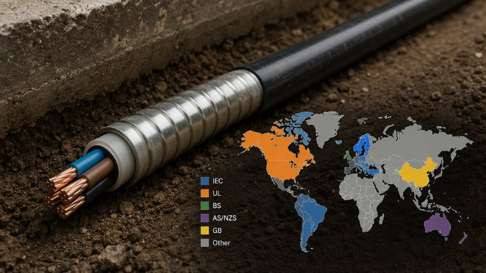
IEC 60364 and IEC 60502: The International Baseline
IEC 60364 (Low-voltage electrical installations) is the foundation most of the world works from, particularly across Asia, the Middle East, and large parts of Africa. Part 5-52 covers wiring system selection and erection, including direct-buried cables, and references installation method D (direct burial in soil) for ampacity purposes. What it doesn’t do is hand you a single universal depth figure — it sets principles and directs you to national implementation.
IEC 60502 is the cable construction standard: Parts 1 and 2 govern low- and medium-voltage power cables respectively, specifying the armour, insulation, and sheathing requirements that make a cable suitable for direct burial in the first place. If you’re procuring internationally, cross-referencing the cable’s test certification against IEC 60502 is your first filter. A cable described as “armoured” without that certification may not have passed the minimum mechanical crush, impact, or water-penetration tests the standard demands.
BS 7671 and ENA G39: The UK and Commonwealth Framework
BS 7671 (18th Edition, AMD 2 as of 2022) is the IET Wiring Regulations and applies directly in the UK and, with local amendments, across many Commonwealth jurisdictions. Installation Method D — direct burial in soil — is the reference method for buried cables in Appendix 4, and the associated current-carrying capacity tables are built around it. Burial depths align with the figures covered earlier in this article: 450 mm under footpaths, 600 mm in open ground, 900 mm under roads.
For utility-scale or distribution-network work in the UK, ENA Engineering Recommendation G39 sits above BS 7671 in practical authority. It specifies additional requirements for trench construction, cable separation from other services, and marker tape placement. An installer who’s compliant with BS 7671 but hasn’t checked whether the project falls under G39 may fail a DNO inspection. That’s an expensive lesson to learn after backfilling.
NEC Article 300 and Table 300.5: The US Requirement
The US National Electrical Code (NFPA 70) handles direct burial in Article 300, with Table 300.5 being the specific reference for minimum cover requirements. Cover depth varies by circuit voltage, cable type, and location — under a building, under a road, in conduit versus direct-buried. For direct-buried cables rated up to 600 V in general locations, the NEC typically requires 600 mm (24 inches) of cover; reduced depths apply when the cable is in conduit or under concrete.
The NEC recognises Type USE-2 cables and listed armoured types (including MC cable in certain configurations) for direct burial. The key word is listed — if the cable isn’t UL-listed or otherwise recognised by the Authority Having Jurisdiction, it doesn’t matter how well you’ve installed it.
All UL-listed armoured cables are automatically approved for direct burial under the NEC.False
UL listing confirms a cable meets a product standard, but NEC Article 300 and Table 300.5 impose additional installation-method and cover-depth requirements. The cable must also be explicitly rated or listed for direct burial — not all armoured cable types qualify.
AS/NZS 3000 and AS/NZS 1429: Australia and New Zealand
The Australian and New Zealand Wiring Rules (AS/NZS 3000) take a notably conservative position on burial depths, and in practice local utilities frequently impose amendments that go further than the base standard. AS/NZS 1429 governs the cable construction side — insulated cables for underground use — and should be checked alongside 3000 for any project in those markets.
One distinctive requirement in AS/NZS 3000 is the mandatory use of marker tape above the cable, placed at a specified distance above the cable top, combined in many jurisdictions with mechanical protection tiles or covers. This isn’t optional and it isn’t left to the installer’s judgement. Inspectors will ask for evidence it was done.
IEC 60287 and IEC 60853: The Engineering Calculation Standards
These two standards aren’t installation codes — they’re the mathematical engine behind all ampacity and derating work. IEC 60287 covers steady-state current ratings; IEC 60853 handles cyclic and emergency loading. Any serious cable sizing exercise for a direct-buried installation should reference both, particularly where soil thermal resistivity data from site investigation is being fed into the calculation. A designer who sizes cable purely from a manufacturer’s table without checking whether the soil conditions match the table’s assumptions is working with incomplete information.
The Practical Compliance Workflow
The sequence matters. Identify the project jurisdiction. Confirm which standard is the primary legal instrument — and check whether the local Authority Having Jurisdiction or utility has issued amendments that supersede it, because they often do. Document the cable selection rationale, the installation method, the burial depth, and the derating assumptions in a technical submission before work starts. Get inspection sign-off before backfilling. That last point sounds obvious, but a surprising number of disputes arise precisely because the cable was covered before the inspector arrived.
Jinda’s armoured cables are type-tested and certified to IEC, BS, and other major international standards. For project submissions, Jinda’s technical team can supply test certificates, construction data sheets, and application-specific notes — the documentation package that an AHJ or a client’s engineer will actually need to sign off a compliance submission, not just a product brochure.
Frequently Asked Questions About Burying Armoured Cable
Can I bury SWA cable without conduit?
Yes — and in most situations, that’s exactly how it’s designed to be installed. The steel wire armour provides mechanical protection broadly equivalent to rigid conduit, which is why SWA exists as a product category. Wrapping it in duct on top adds cost, trench width, and in practice often adds a false sense of security that leads to sloppier bedding underneath.
The cases where you’d genuinely add conduit or duct: under a block-paved driveway that’s likely to be lifted and re-laid, through a congested services corridor where future cable replacement without excavation would save serious money, or in areas with demonstrably high ground movement. For a straightforward run under a garden or field, conduit is usually unnecessary expense.
What is the minimum depth to bury armoured cable under a driveway?
Under any surface subject to vehicular traffic, the standard minimum is 900 mm to the top of the cable — that’s the BS 7671 and IEC 60364 reference figure. Some local highway authorities push that to 1,200 mm, particularly under adopted roads. Never assume the standard figure is the final word; check with the authority having jurisdiction before you dig. One contractor I’m aware of had to re-lay an entire 80 m run because the local utility required 1,200 mm and the installer hadn’t checked. That’s the kind of expensive lesson that sticks.
Under ordinary open ground the minimum is 600 mm, and under footpaths 450 mm — but deeper is almost always cheaper in the long run than a future strike.
Do I need to earth the armour of a buried SWA cable?
Mandatory, not optional. For low-voltage installations, earth the armour at both ends through proper steel wire armour (SWA) cable glands to provide a low-impedance fault return path. An unearthed armour on a buried LV cable is a genuine shock hazard if the outer sheath is breached.
For medium-voltage single-core cables the situation is more nuanced. Earthing both ends allows circulating currents that can cause real heating losses, sometimes enough to derate the cable significantly. Single-point bonding or cross-bonding becomes necessary depending on circuit length and load. If you’re working above 1 kV, get a power engineer to run the numbers before specifying the earthing arrangement.
Armour earthing at both ends is required for LV SWA cable installations per BS 7671 Regulation 543 and IEC 60364-5-54.True
Both standards mandate a protective conductor connection to metallic cable armour to ensure earth fault currents have a safe return path and that touch voltages remain within safe limits.
How long will a buried armoured cable last?
A correctly specified and installed XLPE-insulated SWA cable with an undamaged outer sheath realistically achieves 30–40 years in service. That range depends heavily on soil chemistry, installation quality, and loading history. Cables buried in aggressive soil — low pH, high sulphate content, stray DC currents from nearby traction systems — will age faster even if everything else was done right. Persistent overloading beyond the derated current-carrying capacity accelerates insulation degradation noticeably; running a cable at 110% of its derated rating continuously isn’t a small infraction, it genuinely compresses service life.
The single biggest killer of buried cable life, in my experience, isn’t the cable itself — it’s a poorly made joint that admits moisture over several wet seasons.
Can I use SWA cable in waterlogged or flooded ground?
SWA cable with a continuous, undamaged HDPE outer sheath handles permanently wet ground well. HDPE’s water absorption is negligible and it resists the mild acids found in most waterlogged soils better than PVC. PVC-sheathed SWA is more vulnerable — if the outer sheath picks up even a small nick during installation and the cable sits in standing water, moisture ingress at that point is a matter of time.
Specify HDPE outer sheath for anything going into flood-prone ground, inspect the sheath with a holiday detector before backfilling, and use fully sealed, resin-filled joint kits rather than heat-shrink-only solutions.
What cable do I need to bury for a garden or outdoor power supply?
For a typical domestic garden supply — outbuilding, pond pump, outdoor sockets — a 2-core or 3-core 0.6/1 kV SWA cable with PVC insulation covers most situations. Size the conductor cross-section for the actual load with the buried derating factors applied; people regularly under-size garden cables and then wonder why the breaker trips when the workshop is running. Minimum 600 mm depth under open ground, 450 mm under a garden path.
Earth the armour at the consumer unit end through a proper SWA gland — don’t improvise with a jubilee clip and a bit of green/yellow wire. The outdoor termination should use an IP66-rated gland minimum, and the enclosure at the far end needs to match the environment.
Is direct burial cheaper than installing cable in duct?
Lower upfront cost, not necessarily lower whole-life cost. Direct burial skips duct material and usually allows a narrower, simpler trench. For a one-off permanent installation in stable ground — a substation feed, a rural distribution run — direct burial is often the right economic call.
Cable-in-duct wins on whole-life cost wherever cable replacement is a realistic prospect: urban installations with complex services, high-voltage infrastructure with anticipated load growth, or anywhere ground reinstatement is expensive. Pulling a replacement cable through existing duct typically costs 10–25% of the cost of re-excavating, depending on depth and surface type. For permanent MV or HV infrastructure, the duct option is frequently cheaper over a 30-year horizon even though it costs more on day one.
Choosing the Right Jinda Armoured Cable for Your Direct-Burial Project
Everything covered in this article — soil assessment, derating calculations, trench preparation, jointing integrity — ultimately converges on one practical decision: which cable do you actually order? Getting the installation method right with the wrong cable specification is a common, expensive mistake. Here’s how Jinda’s armoured cable range maps to the scenarios discussed above.
LV and MV Product Lines for Direct Burial
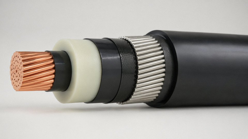
Jinda’s core direct-burial offering at low voltage covers 0.6/1 kV SWA cables with copper or aluminium conductors, available in 2, 3, 3+1, 4, and 5-core configurations from 1.5 mm² up to 400 mm². That range covers the overwhelming majority of site distribution, substation outgoing, and plant infrastructure projects. For medium voltage — 6/10 kV through to 26/35 kV — Jinda produces XLPE-insulated SWA and AWA cables with copper conductors, the latter using aluminium wire armour where magnetic losses in single-core circuits are a design concern. These aren’t niche catalogue items assembled to order; they run as standard production across Jinda’s five manufacturing bases.
For industrial plant work, armoured instrumentation cables and armoured control cables for direct burial are part of the standard portfolio. In practice, these get overlooked in the initial cable schedule and then become urgent late in a project. Jinda can supply screened, individually armoured pairs and triads alongside power cables in the same order — which matters for EPC contractors trying to consolidate procurement.
Matching Outer Sheath to Soil Conditions
This is where the earlier soil assessment section pays off commercially. Standard PVC outer sheath is adequate for most neutral, well-drained soils. Where site surveys show elevated chloride or sulphate content, pH below roughly 5 or above 9, or persistent waterlogging — conditions common in coastal reclamation projects, former industrial land, and parts of sub-Saharan Africa and Southeast Asia — a HDPE outer sheath variant provides meaningfully better chemical resistance and lower moisture permeability over a 30-plus year service life. Jinda supplies both sheath variants as standard production runs. There’s no minimum order premium for specifying HDPE over PVC, which removes one of the usual procurement barriers on smaller infrastructure jobs.
Large-Project Logistics and Lead Time
Five production bases across China totalling 470,000 m² of manufacturing floor space means parallel production across multiple conductor sizes is a real operational capability, not a marketing claim. For infrastructure and utility projects requiring, say, several thousand metres each of four or five different sizes — the kind of schedule common on industrial park power distribution or grid extension work — Jinda can run those concurrently rather than sequentially. Lead time on large orders drops considerably as a result. Drum scheduling and length optimisation are offered as part of the technical support service, which directly reduces the number of underground joints on critical routes. Given that joints are statistically the most common failure point in buried cable systems, fewer joints is a genuine engineering benefit, not just a convenience.
Jinda supplies armoured cables to infrastructure projects in more than 50 countries across Southeast Asia, the Middle East, Africa, and Europe.True
This is stated as a company fact by Jinda Special Cable Group and reflects their documented international supply activity since 1987.
Technical Support Before and After the Order
Pre-order cable sizing and derating calculations using IEC 60287 — accounting for soil thermal resistivity, installation depth, grouping, and ambient ground temperature — are available from Jinda’s technical team at no cost. For utility and EPC clients, Jinda provides type test certificates against BS and IEC standards for compliance submissions, and FAT witnessing can be arranged at the production facility. These aren’t afterthoughts; they’re the kind of documentation that determines whether a cable passes a client’s incoming inspection or sits in a port warehouse while paperwork is resolved.
Jinda’s international sales team works across time zones with customers specifying to BS 7671, IEC 60364, and various national equivalents. If you have a project in progress — or one moving from design to procurement — submit your voltage class, conductor size and configuration, total route length, soil conditions from site survey, and applicable installation standard. The team will return a technical proposal covering product selection, derating confirmation, and delivery scheduling. That’s a faster starting point than working through a generic cable catalogue alone.