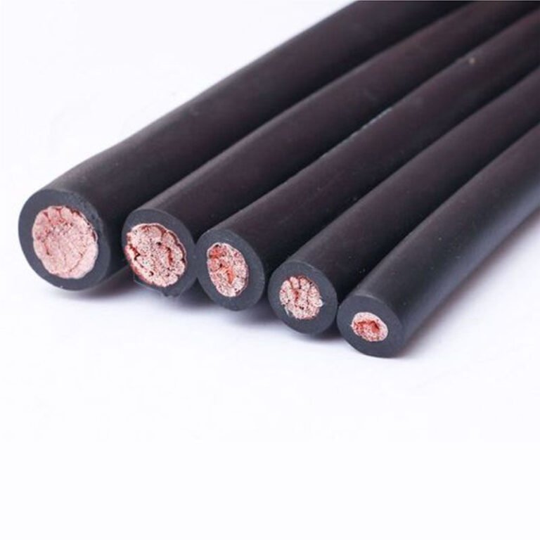
Wiring errors in control circuits don’t announce themselves politely. A misidentified cable run — signal-grade wire pulling double duty on a motor starter circuit, or unshielded conductors routed too close to a VFD — shows up as intermittent faults, ghost trips, and the kind of nuisance downtime that maintenance logs quietly accumulate for months before anyone traces it to the cable itself. The financial drag is real: unplanned stoppages on a mid-size production line can run anywhere from a few hundred to several thousand dollars an hour depending on the process, and shielded control cable that might have prevented the whole situation costs a fraction of one hour of lost output.
Control cables are purpose-built multi-conductor cables, typically rated 300/500 V to 450/750 V, designed to carry instrumentation signals, switching commands, and low-power control circuits reliably in industrial environments. Their advantages include electromagnetic interference attenuation of 40–85 dB in shielded versions, mechanical flexibility suited to confined cable trays and moving machinery, and insulation systems that maintain stable performance from -40°C to +90°C depending on grade.
What makes them genuinely useful — rather than just “compliant” — goes deeper than the voltage rating on the drum label. The real value shows up in long cable runs through electrically noisy plant environments, in multi-axis machines where a dozen circuits share one conduit, and in procurement decisions where the wrong specification looks identical to the right one until something fails at three in the morning.
Precise Signal Transmission: How Control Cables Preserve Command Integrity
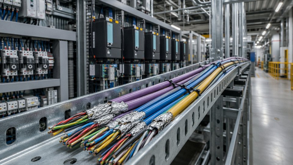
Signal integrity is where control cable engineering gets serious. A control cable’s job isn’t to deliver kilowatts — it’s to carry a 24 VDC command or a 4–20 mA analog signal from a controller to an actuator, accurately, every time, across whatever distance the plant layout demands. Get the electrical parameters wrong and you’re not looking at a tripped breaker; you’re looking at a PLC that misreads a valve position, a conveyor that starts half a second late, or a batch process that drifts out of tolerance while the SCADA screen shows everything green.
Conductor Purity and Resistance: The Foundation
IEC 60228 defines the conductor classes that matter here. Class 1 is solid round copper — low resistance, rigid, best for fixed installations where you need predictable, stable DC resistance over a long run. Class 2 is stranded, which tolerates the kind of minor flexing that happens during installation in a cable tray or when a panel door gets opened and closed over years of service. For control applications, both classes are used depending on application, but the resistance spec is what actually drives signal reliability.
For a 0.75 mm² copper conductor, the DC resistance ceiling under IEC 60228 runs to roughly 26 Ω/km for Class 1 and under 26 Ω/km for Class 2 at 20°C — in practice, well-drawn copper from a controlled manufacturing process will come in noticeably under those limits, typically 24–25 Ω/km. Step up to 1.5 mm², and you’re looking at around 12–13 Ω/km. Why does this matter? Run a 0.75 mm² conductor 500 meters from a remote field junction box back to a central DCS panel, and you have a full kilometer of copper in the loop. At 25 Ω/km, that’s 25 Ω total loop resistance. On a 24 VDC circuit powering a digital input with a 3 mA quiescent load, that’s a 75 mV drop — usually fine. Feed a 4–20 mA transmitter loop instead, and the math stays workable. But use a substandard conductor drawing at 32–35 Ω/km and you’re eating into the switching margin in ways that cause intermittent faults that are genuinely hard to troubleshoot. Maintenance teams chase these for weeks.
Capacitance Between Cores: The Crosstalk Problem
When you lay a multi-core control cable in a tray alongside twenty other circuits, inter-core capacitance becomes the quiet troublemaker. The capacitance between adjacent cores in a well-designed control cable typically falls in the 80–200 nF/km range — the actual value depends on insulation wall thickness, core diameter, and whether cores are individually screened. At the low end of that range, high-speed PLC I/O scanning cycles (sub-10 ms update rates aren’t unusual in modern machine control) see minimal distortion. Push toward the high end with a cheaper cable and thin, inconsistent insulation, and you get capacitive coupling between cores: a rapidly switching digital output bleeds noise into an adjacent analog input. In practice this shows up as unstable analog readings that vary with the switching state of nearby outputs — the kind of fault that drives instrumentation engineers to question their sensor calibration before anyone checks the cable spec sheet.
Tight manufacturing tolerances on insulation wall thickness directly control this. A nominal 0.6 mm insulation wall needs to land within ±0.05 to 0.08 mm across production to keep capacitance consistent. This is a process control issue as much as a materials issue — it requires calibrated extrusion lines and in-line spark testing on every meter of production, not just end-of-reel sampling.
Control cables manufactured to IEC 60228 Class 2 conductor standards maintain DC resistance values that prevent signal degradation across cable runs of 500 meters or more in typical 24 VDC industrial control circuits.True
IEC 60228 Class 2 specifies maximum DC resistance limits for standard copper conductors; for 0.75 mm² this is approximately 26 Ω/km, which results in manageable loop resistance even at 500 m runs for 24 VDC digital and 4–20 mA analog circuits when voltage margins are correctly calculated during design.
Dielectric Consistency and Timing in High-Speed I/O
This is underappreciated by purchasing teams and sometimes by younger controls engineers. In a high-speed I/O scan — a motion control application triggering position feedback from a servo drive, for instance — the dielectric properties of the insulation affect signal propagation delay and edge fidelity. Inconsistent insulation walls mean variable dielectric constant along the cable length, which in aggregate introduces timing jitter. For most PLC I/O at 10–100 ms scan rates this is irrelevant. For distributed I/O nodes communicating over EtherCAT or PROFINET at microsecond timing cycles, it starts to matter. Specifying cables with controlled dielectric properties isn’t over-engineering for those applications — it’s the correct call.
Compliance testing against IEC 60189 (which covers low-frequency cables for internal wiring) and IEC 60227 (PVC-insulated cables including conductor and insulation performance requirements) provides the framework. What actually separates acceptable product from good product is the in-house testing regime: verifying conductor resistance, insulation spark test results, and capacitance measurements on production samples before the drums leave the factory. For a procurement manager placing a large order for a new plant fitout, asking for lot-specific test reports — not just a generic type certificate — is the right move. Certificate numbers are easy to print; measured Ω/km values on your specific production lot are what you actually need.
Electromagnetic Shielding Options: Protecting Control Signals in Electrically Noisy Environments
Walk through most process plants or automated assembly lines and you’ll find control cables running in the same cable trays as 480 V power feeders, variable-frequency drives (VFDs), and arc welding returns. That physical proximity is the root cause of most unexplained PLC faults, drifting analog readings, and intermittent drive trips that maintenance crews chase for days. The fix almost always traces back to shielding — or the absence of the right kind.
How Industrial Noise Gets Into Control Circuits
VFDs are the dominant offender in most modern facilities. Their fast-switching IGBTs generate high-frequency common-mode currents that radiate and couple onto adjacent cables — particularly at the 5–50 kHz range where many drive switching frequencies land, and with harmonics extending well into the MHz range. Arc welders inject broadband transients. High-current bus bars create magnetic fields that induce voltages through inductive coupling. Switching power supplies add conducted and radiated noise across a wide spectrum. A 4–20 mA temperature loop running a meter away from a 75 kW VFD without adequate shielding can show 1–3 mA of superimposed noise — enough to turn a ±0.5% transmitter into a useless instrument.
The Three Shield Architectures
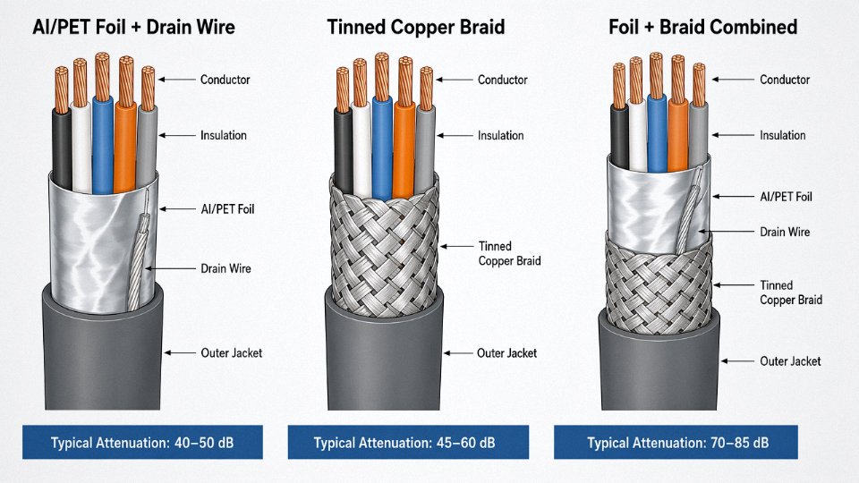
Aluminum-polyester (Al/PET) foil with drain wire is the most common and economical option. The foil wraps the conductor bundle with 100% coverage — no gaps, no weave patterns, complete circumferential contact. It performs well against electric field (capacitive) coupling and handles high-frequency noise above roughly 100 kHz effectively, typically delivering 40–50 dB of attenuation in that range. The drain wire gives you a reliable termination point. The weakness is mechanical: foil is brittle under repeated flex, and in applications with continuous cable movement it can crack and lose continuity without any visible external damage.
Tinned copper braid trades a small amount of coverage — typically 85–98% depending on braid angle and wire count — for significantly better mechanical durability and lower DC resistance. Braid is the right answer for flex applications and anywhere you need a low-impedance ground path. It provides better shielding effectiveness at lower frequencies (below 1 MHz) compared to foil alone, and its mass makes it more tolerant of physical abuse. Coverage percentage matters: a loosely woven 85% braid on a cheap cable is noticeably worse than a tight 95%+ braid. Check the spec sheet, not just the label.
Combined foil-plus-braid is the architecture you reach for in genuinely hostile environments — a cabinet full of VFDs, a welding cell, or any analog loop running parallel to power for more than a few meters. The foil handles high-frequency electric field shielding; the braid adds low-frequency magnetic shielding and gives the assembly mechanical integrity. Combined configurations can achieve 70–85 dB of attenuation across the relevant industrial frequency range, which is sufficient for stable 4–20 mA and 0–10 V signal loops even in close proximity to power feeders.
Individual Core Shielding vs. Overall Shield
For multichannel instrumentation — think a 12-pair cable carrying thermocouple signals from different zones — an overall shield protects the bundle from external noise but does nothing about crosstalk between pairs inside the cable. Individually shielded twisted pairs (each pair with its own foil and drain) reduce inter-circuit crosstalk to negligible levels. In a temperature monitoring system where channels are supposed to be fully independent, crosstalk from an adjacent high-level signal can corrupt a low-level millivolt reading outright. Overall shielding alone won’t solve that.
Grounding: Where Good Shields Fail in Practice
This is where most installations go wrong. A shield grounded at both ends creates a ground loop — any potential difference between the two ground points (and in a large plant, that can be several volts) drives a current through the shield that appears as noise on the signal. The standard practice is single-end grounding at the control panel side, leaving the field end floating. In practice, some engineers leave the field end connected “just to be safe” and then wonder why the shielding is making things worse.
Grounding a control cable shield at both ends always improves noise rejectionFalse
Dual-end grounding creates a ground loop between two reference points at different potentials. The resulting shield current directly induces noise onto the enclosed conductors, often degrading signal quality compared to an unshielded cable. Single-point grounding at the control panel end is standard practice for most industrial signal circuits.
One additional nuance: the drain wire or braid should be terminated with a proper cable gland or EMC gland that makes 360° contact with the shield — not stripped back and twisted into a pigtail. A pigtail termination adds inductance at exactly the frequencies you’re trying to suppress. It’s a small detail that shows up as a measurable performance difference.
Jinda produces both overall-shielded and individually-shielded multi-core control cables designed to IEC 60092, NFPA 79, and customer-specific requirements, covering foil, braid, and foil-plus-braid configurations across the full cross-section range from 0.5 mm² to 10 mm².
Mechanical Durability Advantages: Resisting the Physical Stresses of Industrial Deployment
A cable that transmits a perfect signal but fails mechanically in six months is not a solution — it’s a deferred problem. In practice, mechanical failure is the leading cause of control cable replacement in high-cycle manufacturing environments, and most of those failures trace back to a mismatch between conductor class or jacket material and the actual installation conditions.
Fixed vs. Flex: Conductor Construction Is Not Interchangeable
The distinction between fixed-installation and continuous-flex control cables matters more than most procurement specs acknowledge. Fixed installations — conduit runs, cable trays, panel wiring that gets routed once and left alone — suit Class 1 or Class 2 conductors, which are solid or lightly stranded. These optimize for low DC resistance and dimensional stability, but they work-harden quickly under repeated bending. Run a Class 2 cable through a cable chain on a robot arm and you’ll see intermittent faults within weeks, then outright conductor fracture not long after.
For any application involving continuous movement — machine tools, robotic welders, overhead cranes, automated storage and retrieval systems — you need Class 5 or Class 6 fine-stranded conductors. A Class 6 conductor with wire gauges down around 0.08–0.1 mm per strand can survive 5 to 10 million bending cycles at rated bend radius without fatigue fracture, depending on the cycle speed, temperature, and whether the cable is also twisting. That last variable, torsion, is often ignored at the specification stage and comes back as a warranty dispute.
Jacket Materials: Where the Trade-offs Get Practical
Standard PVC jacket is the right choice for roughly 70–80% of industrial control cable installations. It’s cost-effective, shows good abrasion resistance (typically passing EN 50395 scrape tests at 1.5–2.5 N load), and performs adequately from about -15°C up to +70°C. Below that lower limit, standard PVC stiffens badly — in an unheated northern European warehouse in January, a standard PVC cable can become almost brittle enough to crack at a sharp corner.
Polyurethane (PUR) jacket costs more, usually 20–40% premium over PVC depending on cable diameter and order volume, but it earns that premium in environments with cutting oils, hydraulic fluid splash, or frequent mechanical abuse. Shore A hardness for PUR cable jackets typically runs 85–95, and flex life in torsion-plus-bending test rigs often exceeds PVC by a factor of three to five. For food processing lines that get hosed down with cleaning agents daily, PUR also handles chemical exposure far better.
TPE jacket is the choice when you need halogen-free compliance and cold-temperature flexibility together. It retains usable flexibility down to -40°C, which matters for outdoor installations in northern climates or refrigerated logistics facilities. It’s not as abrasion-hard as PUR in most formulations, so it’s the wrong call for cable drag chains with tight clearances.
| Jacket Material | Abrasion Resistance | Low-Temp Flex Limit | Oil/Chemical Resistance | Typical Application |
|---|---|---|---|---|
| PVC | Good | -15°C | Moderate | General industrial, panel wiring |
| PUR | Excellent | -35°C | High | Machine tools, food processing, offshore |
| TPE | Moderate | -40°C | Moderate | Outdoor solar farms, cold storage, halogen-free zones |
Crush Resistance and the Realities of Plant Floors
Industrial-grade control cables tested per EN 50305 undergo flat-plate crush loading at 2,000 N per 100 mm of cable length. The pass criterion is that all conductor circuits remain electrically intact after the load is released. This matters for cable tray edges — a loaded tray with cables pinched against a sharp steel lip applies surprisingly concentrated force — and for the occasional forklift incident that nobody documents until the line goes down.
Industrial control cables rated to EN 50305 crush test standards must maintain circuit continuity after 2,000 N/100 mm flat-plate loading.True
EN 50305 specifies mechanical performance requirements for industrial data and control cables, including crush resistance testing at this load level to simulate cable tray edge pressure and similar installation stresses.
Steel wire armor (SWA) and steel tape armor (STA) are available for cables that will be direct-buried, run through exposed conduit in high-traffic areas, or installed in environments with risk of rodent damage. SWA handles longitudinal tension well, which makes it the better choice for vertical drops or direct-burial pulls over long distances. STA provides more uniform radial crush protection. Either armor type adds weight and reduces flexibility, so you wouldn’t specify armor for a cable chain application — but for a buried run feeding outdoor machinery, skipping it is a false economy.
Bending Radius: The Spec Nobody Checks Until It’s Too Late
Minimum bending radius for fixed control cable installations is typically 6× the outer diameter. For dynamic flex applications, the figure jumps to 10–15× outer diameter depending on conductor class, jacket material, and whether the cable includes a shield. Exceed these limits during installation — and it happens routinely when cable trays are pulled tight around corners — and the consequences are insulation cracking, conductor strand breakage at the outer arc of the bend, and shield deformation that compromises EMI performance discussed earlier. The damage is often invisible from outside the jacket, so the cable appears fine until it fails under electrical load or after a few thousand flex cycles. Checking bending radius compliance at installation, not just at specification, prevents a category of failures that otherwise looks like “random cable failures” in maintenance logs.
Chemical, Temperature, and Environmental Resistance: Performance at the Extremes
Environmental resistance is where cable specifications get quietly expensive to get wrong. A cable that handles voltage and signal integrity perfectly on a test bench will fail prematurely if the jacket material was chosen for cost rather than the actual plant environment. The consequences are rarely dramatic — usually a slow degradation that shows up as intermittent faults months after commissioning, by which point the original procurement decision is long forgotten.
Matching Insulation Chemistry to the Operating Environment
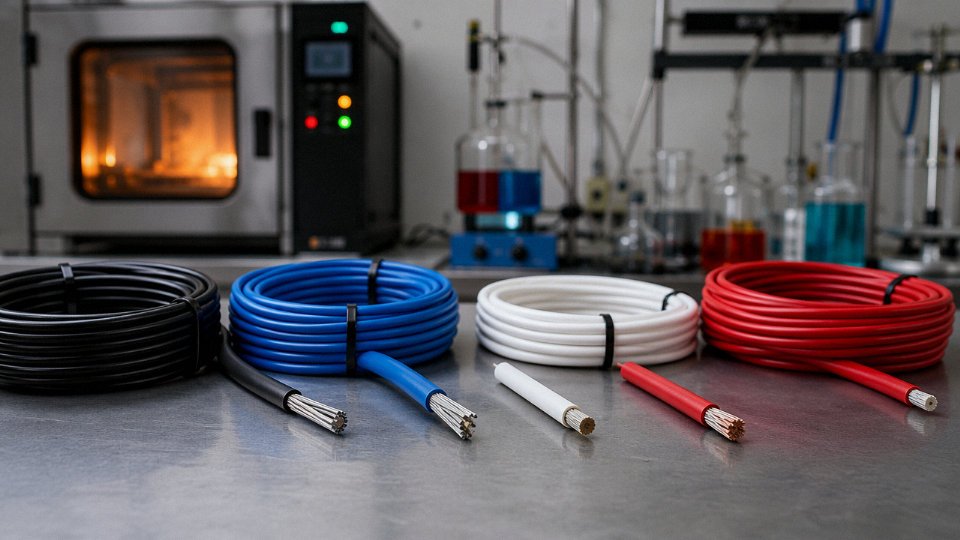
Standard PVC insulation is the default for good reason: it’s cost-effective, reasonably flexible, and handles incidental chemical splash without complaint. What it doesn’t handle well is sustained contact with concentrated hydrocarbons — hydraulic oil, diesel, cutting fluids in machine tool enclosures. Plasticizer extraction from PVC under hydrocarbon immersion causes the jacket to harden and crack, typically within 12–24 months in a real CNC environment. IEC 60811-406 oil immersion testing makes this visible before installation: standard PVC cables commonly show 12–18% mass increase after 24-hour oil submersion, which signals plasticizer leaching. PUR-jacketed or LSZH-PUR hybrid cables typically stay under 5% mass change under the same test. That difference translates directly to jacket service life in a petrochemical valve actuator panel or a hydraulic press control cabinet.
XLPE (cross-linked polyethylene) insulation changes the picture considerably for thermal performance. The cross-linking process converts thermoplastic PE into a thermoset structure that resists both deformation at elevated temperature and chemical attack. Continuous rating sits at 90°C; short-circuit withstand reaches around 250°C. For control cables routed near heat exchangers, steam tracing, or industrial ovens, that thermal margin matters more than the rated operating voltage. XLPE also resists dilute acids and alkalis better than PVC, which is relevant in water treatment plants and battery storage facilities where electrolyte vapors are a factor.
At the extremes, silicone rubber insulation is the only practical choice once you’re above roughly 150°C continuous or below -50°C. Silicon-oxygen backbone chemistry gives it flexibility at -60°C and stability past 180°C. It’s more expensive and mechanically softer than PVC or XLPE — abrasion resistance is noticeably worse — so silicone-insulated control cables belong in static high-temperature installations, not flexible trailing applications.
UV, Ozone, and Outdoor Exposure
Outdoor control cable runs — solar farm tracker wiring, outdoor switchyard control panels, water treatment plant cable trays exposed to direct sun — face UV and ozone degradation that standard PVC simply wasn’t designed for. UV photons break polymer chains at the surface; ozone attacks double bonds. Over a 25-year design life typical for infrastructure projects, this produces surface chalking, micro-cracking, and eventually jacket breaches that let moisture in. Carbon-black-loaded HDPE and UV-stabilized PVC compounds address this through UV absorption and free-radical scavenging. The carbon black loading level matters — it needs to be sufficient and evenly dispersed, not just present as a checkbox. Reputable manufacturers will specify the UV stabilizer system in the compound data sheet.
Moisture Ingress and Water Blocking
For underground or coastal installations, dry-core cable construction is a liability. A single jacket nick allows capillary wicking to travel meters along the cable core. Longitudinal water-blocking tape and gel-filled core construction, tested under IEC 60229, contain ingress at the breach point. In practice, this distinction matters enormously for direct-buried control cables in coastal industrial zones where the water table is high and jacket damage during installation is nearly inevitable on a large site.
Fire Performance and LSZH
Fire performance grades are frequently underspecified until an insurer or building authority asks the question at commissioning. IEC 60332-1 covers a single vertical cable flame — a fairly easy bar. IEC 60332-3 covers cable bundle flame spread, which is the relevant test for densely packed cable trays. The harder requirements are IEC 60754 (halogen gas emission, critical because hydrogen chloride from burning PVC is both toxic and corrosive to electronics) and IEC 61034 (smoke density, which determines visibility in evacuation routes). LSZH formulations meet all four. For tunnels, data centers, rail, and public buildings, LSZH isn’t optional — it’s the baseline.
LSZH cables emit significantly less toxic gas and smoke than standard PVC cables when exposed to fire, reducing risk to personnel and installed equipment.True
IEC 60754 halogen emission testing and IEC 61034 smoke density testing consistently demonstrate that LSZH compounds produce lower halogen acid gas concentrations and higher light transmittance during combustion compared to PVC-jacketed cables.
Holding CE, UL, and DNV-GL marine approvals under a single manufacturer’s product line isn’t a minor convenience — it collapses procurement documentation significantly for international EPC projects where the same cable type may need to satisfy European, North American, and offshore certifications simultaneously. Chasing multiple approval bodies across multiple suppliers adds weeks to a project qualification process and introduces the risk of spec drift between supposedly equivalent products.
Multi-Core Flexibility and System Integration: Simplifying Complex Control Architectures
Walk into any older automated production line that was wired with individual single-core conductors and you’ll see the problem immediately: cable trays packed to the brim, gland plates drilled to the point where the steel looks like a sieve, and conduit runs so congested that pulling a replacement wire becomes a half-day job involving two electricians and a fish tape. Multi-core control cables exist largely to solve this, and they do it well.
Core Count Ranges and What Consolidation Actually Buys You
Standard catalog offerings typically run from 2 cores up to 61 cores, with cross-sections from 0.5 mm² to 6 mm² per core covering the vast majority of industrial control applications. Custom builds — for large panel builders, shipbuilders, or process plant contractors — commonly go to 100+ cores in a single assembly. That’s not exotic; it’s just a matter of specifying it early enough in the project.
The practical payoff is real and immediate. Conduit fill calculations change dramatically when 24 discrete conductors collapse into a single 24-core cable. You’re reducing gland-plate penetrations from 24 holes to one, which matters enormously in sealed enclosures where every additional penetration is a potential IP rating failure point. Cable tray congestion drops, cable tray support loading drops, and the fire load in the cable run drops. These are not trivial considerations in an IEC 61439-compliant panel room or a Zone 2 hazardous area installation.
Identification Systems That Actually Work Under Pressure
Color coding and core numbering matter more than people give them credit for. IEC 60446 and DIN VDE 0293 define sequential numbering schemes and color sequences that field technicians can work with under pressure — at 2 a.m. during a breakdown, in a panel with poor lighting, with a maintenance window of 90 minutes. Printed alphanumeric core identification at regular intervals along each insulated conductor means a technician can pick up any core at any point in the run and know exactly which circuit they’re holding without tracing back to the panel. That’s the whole point.
In practice, cables that use only color coding without printed numbers become ambiguous past about 5 cores because color sequences repeat. For anything above 5 cores, numbered cores are worth specifying explicitly.
Quantifying the Labor Savings
Replacing 24 individual single-core conductors with a single 24-core control cable can reduce cable pulling time by roughly 70%, gland entries by 23, and field termination time by around 40%.True
These figures are consistent with industrial installation benchmarks based on pulling one cable assembly versus 24 individual cables through the same conduit or tray run, and reducing gland terminations from 24 to one per entry point. Termination time savings reflect faster core identification through standardized numbering versus individual conductor tracing.
That 40% reduction in termination time adds up fast on a large machine build. A panel with 10 multi-core cable entries instead of 240 individual gland entries is a fundamentally different project for the installation crew.
Scalability and Machine Design Alignment
Multi-core cables align naturally with IEC 60204-1 machine wiring practice. When a machine builder adds a servo axis to an existing platform, the control architecture change ideally means specifying one additional control cable — not re-engineering a conduit run or renegotiating tray space. This is the modular wiring philosophy that serious machine builders follow, and it’s why having a cable manufacturer who can supply identical cables on repeat orders to exact cut lengths matters. Jinda supplies cables on drums up to 10,000 m with custom cut-length options, which eliminates on-site splicing entirely. Spliced control cables are a chronic source of intermittent faults that are genuinely difficult to diagnose — voltage drop across a poorly crimped splice changes under thermal cycling and load variation in ways that look like a PLC input fault rather than a wiring fault.
Twisted Pairs and Triads Inside Multi-Core Assemblies
Not every circuit in a control cable runs single-ended. Profibus DP, DeviceNet, and 4–20 mA analog loops all benefit from twisted-pair or triad constructions within the cable assembly. A 12-pair twisted cable running both digital fieldbus and analog instrumentation signals in the same sheath is a reasonable configuration for a compact machine — provided the pairs are individually identified and the overall shielding is appropriate for the noise environment. The twist lay length affects differential noise rejection; tighter twist lay generally gives better common-mode rejection, which is why specifying a fieldbus-rated twisted pair within the assembly is worth the slight cost premium over an untwisted multi-core when running Profibus at 1.5 Mbit/s over distances beyond roughly 50 m.
The bottom line is that multi-core construction is a system-level efficiency tool, not just a packaging convenience. The cable tray, the panel, the commissioning schedule, and the long-term maintenance burden all look different when the wiring architecture is built around consolidated multi-core cables from the start.
Long-Term Cost Economics: Total Cost of Ownership vs. Initial Cable Price
Purchase price dominates most cable procurement conversations. It shouldn’t. Over a 20–30 year asset life, the initial material cost of control cabling typically accounts for only 15–25% of total cost of ownership — the exact share depends on industry sector, installation complexity, and how hard the environment is on insulation. The remaining 75–85% sits in installation labor, commissioning, periodic inspection, unplanned downtime, and eventual replacement. Optimizing only for purchase price is, in practice, optimizing for the smallest slice of the problem.
Where the Money Actually Goes Over a 25-Year Asset Life
Break TCO into its real components and the math becomes uncomfortable for anyone who has been buying on lowest unit price. Installation labor and termination work alone often run 3–5× the cable material cost on a complex control system — conduit pulling, lacing, labeling, continuity testing, loop checking. That cost is paid once regardless of cable quality. Replacement, when it happens at year 12 instead of year 25, means paying that labor bill a second time, plus the engineering cost of re-commissioning affected control loops, plus whatever production was lost during the outage window.
Maintenance inspection cadence is a real and often underestimated cost. PVC-jacketed cables in oily sumps, outdoor tray runs, or near UV sources generally need formal inspection every 2–3 years and start showing jacket embrittlement and cracking somewhere between year 10 and year 15 depending on the severity of exposure. Correctly specified PUR-jacketed cables in the same oily environment, or XLPE-insulated cables in UV-exposed outdoor trays, routinely run to 25–30 years with nothing more than an annual visual walkdown. That difference — say, four or five formal inspection cycles eliminated over a project life — translates to real technician hours, scaffolding if the runs are elevated, and documentation overhead.
The Arithmetic of One Unplanned Trip
A single process trip caused by insulation failure in a critical control loop is where the economics of cable specification become brutally clear. Depending on the industry, lost production costs from an unplanned shutdown run roughly $50,000 to $500,000 per hour — closer to the low end for a batch chemical process, toward the high end for a continuous casting line or offshore platform. Even a two-hour trip in a mid-tier process plant easily exceeds $100,000 in lost margin before you account for restart costs, waste, and the maintenance call-out itself.
The incremental cost of upgrading to a higher-specification control cable is negligible compared to the cost of a single unplanned process trip it may prevent.True
A premium-specified shielded PUR control cable might cost 20–35% more per meter than a basic PVC equivalent. On a 500-meter run, that premium is typically a few hundred dollars. A single avoided process trip worth $100,000+ makes the ROI of the upgrade self-evident.
The insidious failure mode isn’t usually the catastrophic trip, though. It’s the nuisance. Out-of-tolerance conductor resistance — which shows up in undersized or poorly drawn conductors — causes intermittent faults on sensitive PLC analog inputs. These generate repeated call-outs: a technician goes to the panel, finds nothing obviously wrong, clears the alarm, logs it as “investigated, no fault found.” Do that six times over two years and you’ve spent more in labor than the price premium of a correctly specified cable would have cost on day one. Under-specified shielding on an analog measurement loop causes slow drift that gets attributed to the instrument, triggering instrument re-ranging or even replacement before anyone looks at the cable. Both failure patterns are common and both are preventable at the specification stage.
Procurement Economics of Buying Right at Scale
Spot-market purchasing of control cable — buying what’s available from a distributor when a project needs it — carries real cost penalties beyond unit price. Batch inconsistency is the one most engineers don’t think about until it causes a problem: conductor resistance or capacitance varying between delivery lots can shift loop behavior enough to require re-calibration. Lead time uncertainty forces over-ordering and tying up working capital in inventory.
Blanket-order agreements with a vertically integrated manufacturer address all of this. With five production bases and roughly 470,000 m² of manufacturing capacity, Jinda can support volume agreements that lock pricing across a project lifecycle, guarantee batch consistency from a single production line, and typically reduce per-meter cost by 8–15% versus equivalent spot purchases — the actual saving depends on annual volume and contract length, but even the low end of that range compounds meaningfully on a large cable package.
A Simplified 25-Year NPV View
Run a stripped-down NPV comparison: premium-specified control cable at roughly 1.3× the purchase price of a standard equivalent, against standard cable. Credit the premium scenario with one avoided process trip every five years (conservative for a continuous process), two fewer formal inspection cycles over the project life, and a replacement cycle of 25 years instead of 12–15. Discount at a modest rate. In virtually every industrial scenario where control cabling serves a critical loop, the premium specification returns positive NPV — often within the first five years. The cases where standard cable wins on NPV are genuinely narrow: non-critical, easily accessible, low-consequence loops where a trip causes no production loss and replacement takes an hour. Those exist. They’re not the majority of a plant’s control cable inventory.
Specifying correct cable quality is not a premium for its own sake. It’s the cheaper decision, correctly accounted for.
Selecting the Right Control Cable for Your Application: A Practical Engineering Checklist
Getting the specification right before you issue a purchase order saves far more time and money than any post-installation fix. Misspecified control cables are responsible for a disproportionate share of commissioning delays — not because engineers don’t know their systems, but because the translation from system design to cable datasheet gets rushed. The six parameters below form a working checklist, not a theoretical framework.
Voltage and Current Rating
Start with system operating voltage and confirm whether your circuits run at 300/500 V or 450/750 V. Neither is “better” — it depends on your control panel design and any local code requirements. The more important check is transient headroom: inductive switching loads and VFD output lines can generate voltage spikes well above the nominal rail, so the rated voltage of your cable needs to exceed your worst-case transient, not just your steady-state operating voltage. Then calculate voltage drop across the full cable run length at continuous load current. On long runs — anything over roughly 80–100 m carrying a 4–20 mA analog signal — conductor cross-section starts to matter even though the current is small, because the loop resistance affects signal accuracy at the receiving end.
Core Count and Circuit Architecture
List every circuit the cable must carry before you open a catalogue. Group them by signal type: digital I/O circuits can usually share a multicore without special precautions, but a 4–20 mA analog loop running next to an RS-485 data pair in the same unshielded cable is asking for trouble. Thermocouple extension circuits are the most sensitive and should either run in dedicated cables or, at minimum, in individually shielded pairs within a composite cable. Paired or triaded construction — rather than plain multicore — matters wherever common-mode noise rejection or impedance matching is a functional requirement.
Shielding Requirement
Use IEC 61000-4-3 zone classification as a starting framework even if full EMC compliance testing isn’t mandatory for your project. In practice: light industrial environments with some contactor switching get by with foil-only shielding (typically 40–60 dB attenuation). Heavy plant — near large motor drives, welding equipment, or high-frequency induction systems — warrants foil-plus-braid construction, which can reach 85 dB attenuation in well-terminated installations. Mixed analog and digital circuits in a single cable almost always need individual pair shielding, regardless of overall environment severity. Shield termination at one end only for most analog circuits; both ends for RF-heavy environments. This detail rarely makes it onto a purchase order, but it determines whether the shield helps or creates a ground loop.
Foil-plus-braid shielded control cables can achieve up to 85 dB EMI attenuation in industrial environments.True
This level of attenuation is achievable with properly constructed overall foil-plus-braid shields and correct low-impedance termination at both ends; attenuation figures below 40 dB typically indicate foil-only construction or poor shield termination practice.
Mechanical Installation Class
Fixed tray or conduit installation is the least demanding mechanically — standard Class 2 stranded conductors and a PVC outer jacket will cover most of these applications. Occasional flex during maintenance access is a middle category that many engineers underspec; cables bent repeatedly during routine panel access fail earlier than expected if specified for static installation. Continuous dynamic flex in cable tracks or festoon systems requires Class 5 or Class 6 fine-stranded conductors and a jacket compound — typically PUR rather than PVC — rated for the specific bend radius and cycle count of the application. Get the track manufacturer’s bend radius specification before finalizing the cable order.
Environmental Exposure
Map your site conditions systematically: operating temperature range including cold-bend temperature at installation (relevant in unheated facilities in northern climates during winter commissioning), continuous service temperature, chemical and oil exposure, UV if the cable runs outdoors or near skylights, and any submersion risk. A cable rated for –40 °C to +90 °C covers most industrial HVAC and general plant applications, but oil-resistant jacketing, halogen-free compounds, or direct burial ratings each require a deliberate material choice, not a default.
Certification and Compliance
Identify the regulatory framework for the end market — CE marking for European installations, UL/CSA listing for North America, DNV-GL approval for marine and offshore, ATEX/IECEx for explosive atmosphere zones — and then verify that the manufacturer holds a current, auditable certificate for the specific cable construction you are ordering. A corporate ISO 9001 certificate does not substitute for a cable-type approval. Request the certificate number, confirm it covers the exact rated voltage and construction, and check expiry dates.
Incoming Inspection
Regardless of supplier reputation, a minimum incoming inspection protects the project. Measure conductor resistance and compare against IEC 60228 Class limits. Run an insulation resistance test at 500 VDC — values below roughly 100 MΩ·km on new cable warrant rejection or a call to the supplier before installation. Check shield continuity end-to-end. Verify drum marking matches the purchase specification on conductor count, cross-section, voltage rating, and certification mark. This takes an afternoon on arrival and prevents weeks of fault-finding after commissioning.
Frequently Asked Questions About Control Cable Advantages and Applications
Engineers and procurement staff tend to hit the same walls repeatedly when specifying control cables. These questions come up in factory acceptance tests, during installation troubleshooting, and — unfortunately — after a commissioning failure that could have been avoided. Here are straightforward answers drawn from real application experience.
Can I use a power cable instead of a control cable for control circuits?
Technically, some electrical codes don’t outright prohibit it. In practice, it’s a bad idea for several reasons that compound over time. Power cables are sized for load current — you end up with 4 mm² or 6 mm² conductors carrying 50 mA control signals, which is wasteful in conduit fill and cost. They typically have two to four cores with no color-coded identification scheme suited to multi-device control wiring, so your maintenance crew will be tracing conductors with a tone probe instead of reading a label. No shielding means every VFD-laden panel becomes a noise injection point. The capacitance characteristics are optimized for nothing in particular. You can make it work on a simple on/off circuit, but the day someone has to fault-find a nuisance trip at 2 a.m., they’ll understand why the original specifier made the wrong call.
How many cores do I need for a standard motor starter circuit?
A basic direct-on-line starter — start pushbutton, stop pushbutton, one auxiliary contact for seal-in, one for remote run indication, a fault output, and two common returns — lands you at roughly 7 to 10 cores depending on how the common returns are arranged. Add a local/remote selector and an hour-run meter pulse output and you’re at 12. A VFD installation with a remote keypad, analog speed reference (4–20 mA), run/fault feedback, and a couple of digital inputs typically needs 12 to 16 cores. IEC 60204-1 recommends carrying 10–20% spare cores on every run, which is cheap insurance — pulling a new cable through a finished cable tray because you ran out of cores is expensive and disruptive.
What is the maximum run length before signal degrades?
It depends entirely on the signal type, which is the honest answer. For 24 VDC digital I/O with standard PLC input impedance, 1.5 mm² conductors will handle runs up to roughly 1,000 m without issue. Analog 4–20 mA loops are governed by loop resistance budget — most transmitters and receivers allow a total loop resistance of around 600 Ω, so your conductor cross-section directly limits run length; at 0.75 mm² you might be capped at 200–300 m, while 2.5 mm² opens that up considerably. RS-485 has a protocol-defined ceiling of 1,200 m at 100 kbps. Run longer than that and you need a repeater, not a heavier cable.
Should control and power cables share the same cable tray?
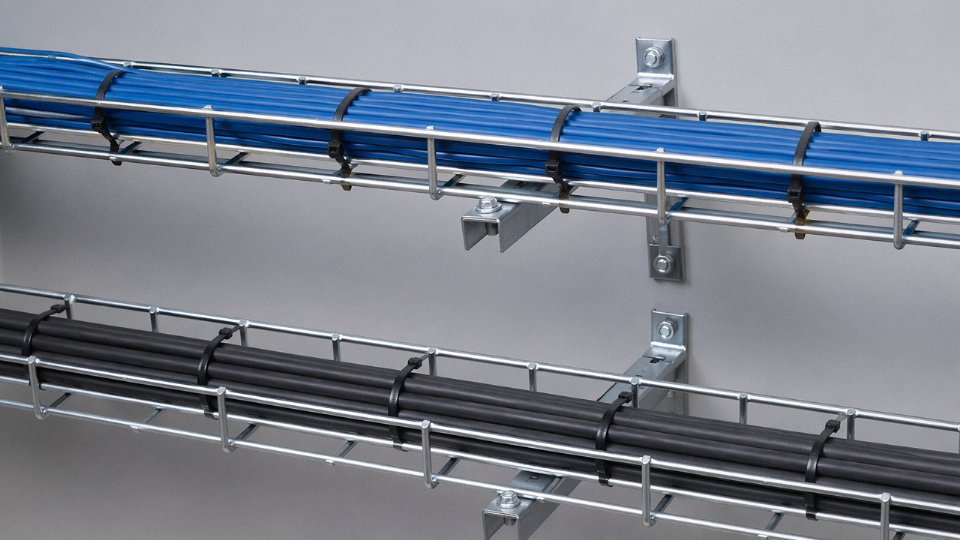
No, unless you separate them properly. IEC 60364-5-52 requires at least 50 mm physical separation or a grounded metallic divider between control and power cable groups. Unshielded control cables should stay at least 200 mm away from VFD output cables — those output lines carry high-frequency PWM switching transients that couple aggressively into adjacent conductors. This isn’t a theoretical concern; it’s a common root cause of unexplained PLC input faults in plants with dense tray routing.
LSZH versus standard PVC — when does it matter?
Standard PVC cable in a fire can emit 20% or more hydrogen chloride by mass and reduce visibility in an enclosed corridor to near zero within minutes. LSZH (low smoke zero halogen) cable limits halogen acid gas emission to below 0.5% and achieves greater than 60% light transmittance in standardized smoke tests. Specify LSZH in tunnels, marine vessels, offshore platforms, data centers, metro rail installations, and any enclosed public space where people need to walk out through smoke. In an open outdoor industrial yard, standard PVC is usually fine and cheaper. The performance gap is real but only matters in specific scenarios.
LSZH control cables emit less than 0.5% halogen acid gas under fire conditions and achieve greater than 60% light transmittance in smoke tests per IEC 60754 and IEC 61034 test standards.True
These values are standardized test thresholds defined in IEC 60754-2 (halogen content) and IEC 61034-2 (smoke density), and compliant LSZH cables must meet them to carry the designation. They are verifiable against manufacturer test reports.
How does Jinda support customers with custom specifications?
Jinda’s engineering team reviews your technical datasheet or project specification, proposes a compliant cable construction referencing IEC, UL, or customer-proprietary standards as applicable, and provides pre-production samples with full test reports before series production begins. Type-approval certification through accredited third-party labs is supported where required. Lead time for custom control cable orders typically runs 15 to 30 working days, though that window depends on core count, jacket material availability, and whether specialty fillers or armoring are involved.
What is the shelf life of an uninstalled cable stored on a drum?
PVC-jacketed control cables stored indoors — 5–35°C, relative humidity below 70%, no direct UV, away from ozone sources like arc welders or corona discharge equipment — will hold full performance for roughly 3 to 5 years. XLPE and LSZH constructions typically extend that to 5 to 10 years under the same conditions. If a drum has been sitting in a warehouse for more than two years, test insulation resistance before installation and do a visual check of the jacket for cracking or surface chalking, especially near the drum core where bending stress concentrates.