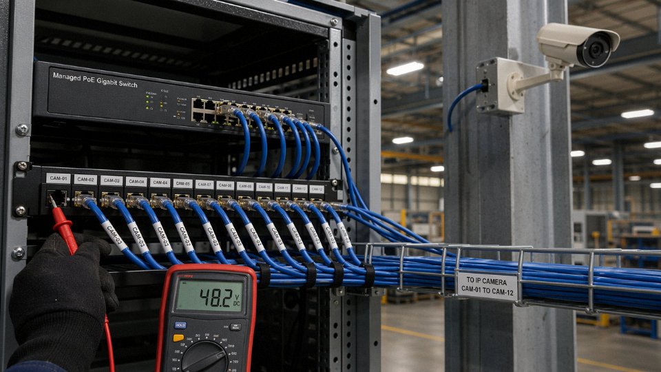
Pick the wrong cable for a Power over Ethernet run and you don’t just get a sluggish network — you get a switch port that trips under load, a camera or access point that resets at peak hours, or a slow thermal failure inside a bundled conduit that nobody notices until a production line goes dark. Undersized conductors and poorly rated insulation are the usual culprits. Getting the voltage question right before procurement saves rework, prevents unplanned downtime, and keeps your cabling infrastructure from becoming the weakest link in an otherwise solid installation.
Standard Ethernet data signaling runs at roughly 1–2.5 V differential on the twisted pairs. Power over Ethernet raises that dramatically: IEEE 802.3af/at delivers 44–57 V DC under load, while 802.3bt Type 4 (PoE++) can reach 71.3 V DC open-circuit and supply up to 90 W at the source — all over the same Cat5e-through-Cat8 cable. The voltage your cable actually needs to handle depends entirely on which PoE standard your equipment uses.
What surprises most engineers the first time they work through an 802.3bt deployment is how quickly the electrical requirements shift from a pure data-cabling problem into something that looks a lot more like low-voltage power distribution — with real consequences for conductor resistance, bundle sizing, and ambient temperature that the data-only spec sheets simply don’t cover.
Data-Signaling Voltage: How Ethernet Physically Encodes Information at the Wire Level
Strip away the PoE discussion for a moment and look at what Ethernet cable is doing in its most basic role: moving logic states from one PHY chip to another, fast enough to be useful, accurately enough to matter. The electrical reality is surprisingly humble.
Differential Pairs and Why the Voltage Is So Small
Each twisted pair in a Cat5e, Cat6, or Cat6A cable carries two conductors that are always driven to opposite polarities — one goes slightly positive while the other goes slightly negative, then they swap. The receiver ignores the absolute voltage on either wire; it measures only the difference between them. That differential approach means electromagnetic interference picked up along the cable length hits both conductors roughly equally, and the noise cancels at the receiver. It also means the actual wire-to-wire voltage swing is modest — typically somewhere between 1 V and 2.5 V peak differential, depending on the speed standard and the specific PHY implementation. Neither conductor is sitting at a hazardous potential relative to ground. This is genuinely a low-energy signal environment.
Encoding Schemes and What They Demand from the Cable
The encoding scheme layered on top of that differential signal changes substantially as speed increases, and it drags the cable’s electrical requirements with it.
At 10 Mbps (10BASE-T), Manchester encoding flips the signal to represent each bit with a mid-bit transition. Voltage swings are relatively large and the timing is slow enough that even marginal cable quality rarely causes problems. Run cheap patch leads in a 10BASE-T installation and you probably never notice.
Fast Ethernet at 100 Mbps uses MLT-3, a three-level scheme that reduces high-frequency spectral content and narrows the required bandwidth, but noise margins tighten compared to Manchester. You start caring more about cable quality here — particularly return loss, which reflects signal energy bouncing back from impedance discontinuities like a poorly terminated jack or a crushed section of cable.
Gigabit Ethernet (1000BASE-T, PAM-5) encodes five discrete voltage levels simultaneously across all four pairs, running full-duplex on every pair at once. The voltage steps between PAM-5 levels are small — fractions of a volt — and the noise margin shrinks proportionally. A cable with a bad punchdown, a sharp bend that deforms the pair geometry, or inconsistent twist rates will introduce crosstalk and return loss that were invisible at 100 Mbps but fail link training at 1 Gbps.
10GBASE-T pushes this further with PAM-16, sixteen discrete voltage levels. The signal swing barely changes from PAM-5, but distinguishing sixteen levels instead of five demands dramatically tighter noise floors. Cable category becomes non-negotiable: a Cat5e link that trains at 1 Gbps may simply refuse to run 10G, not because of any damage, but because the insertion loss curve at 500 MHz is a few dB worse than Cat6A allows.
Where the PHY Chip Fits — and What Happens When Wiring Goes Wrong
The PHY chip at each end sets and interprets these precise voltage levels. It is also the component that suffers first when something goes wrong. A wiring fault that connects one side of a pair to ground, or a splice that mixes pairs from two different cable runs with mismatched impedance, can inject common-mode voltage that the receiver’s front end was not designed to reject. Transceiver damage from wiring errors is more common than people admit — I’ve seen a rack of SFP+ modules lose RX ports one by one before someone traced the fault back to a cable bundle where two runs had been swapped at a patch panel.
Insertion Loss and Return Loss: The Factory’s Responsibility
From a cable manufacturer’s perspective, insertion loss and return loss are voltage-domain parameters specified across a frequency range, not just a single number. Insertion loss describes how much signal voltage is attenuated by the time it reaches the far end — too high, and the PHY’s equalizer runs out of range. Return loss describes reflections at impedance boundaries — too low (too many reflections), and the received signal is corrupted by ghost images of itself. Both are controlled through consistent dielectric materials, tight twist-rate tolerances, and precise conductor geometry maintained across every meter of the reel.
At the data-signaling level, then, Ethernet cable is carrying milliwatts of signal power, voltages that would not light an LED. The voltage story changes entirely once a PoE injector or switch port enters the picture.
Power over Ethernet Voltage Generations: From IEEE 802.3af to 802.3bt and What Changed
PoE didn’t arrive fully formed. It evolved in three major steps over roughly fifteen years, each step pushing more voltage and wattage down the same Cat cable — and each step creating new compatibility headaches for anyone who inherited a mixed-generation infrastructure.
Here’s the reference table most project specs leave out:
| Standard | Year | Common Name | Nominal Voltage at PSE | Min Voltage at PD | Max Power at PSE | Max Power at PD | Pairs Used |
|---|---|---|---|---|---|---|---|
| IEEE 802.3af | 2003 | PoE | 44–57 V DC | 37 V DC | 15.4 W | 12.95 W | 2 (phantom feed) |
| IEEE 802.3at | 2009 | PoE+ | 50–57 V DC | 42.5 V DC | 30 W | 25.5 W | 2 (phantom feed) |
| IEEE 802.3bt Type 3 | 2018 | PoE++ / 4PPoE | 50–57 V DC | 42.5 V DC | 60 W | 51 W | 4 |
| IEEE 802.3bt Type 4 | 2018 | PoE++ / 4PPoE | 52–57 V DC | 41.1 V DC | 90 W | 71.3 W | 4 |
Why the Source Voltage Has to Be Higher Than What the Device Receives
This is the part that catches people off guard when they’re laying out a building network for the first time. The cable isn’t just a wire — it’s a resistor. A 100 m horizontal run of Cat 5e has a DC loop resistance of roughly 18–25 Ω per pair depending on conductor gauge and temperature, and TIA-568 sets a ceiling of 12.5 Ω per conductor (25 Ω loop) for the horizontal channel. At 802.3at currents, that resistance drops anywhere from 3 to 7 V along the cable before the powered device ever sees it. So if the PSE put out exactly 44 V, a device at the far end of a long, warm cable run would see something in the high 30s — below the minimum negotiation threshold and below what most PDs will accept.
That’s why the standards specify PSE output in the 50–57 V range rather than at the minimum PD voltage. The headroom is deliberately baked in to absorb cable loss.
Phantom Feed vs. Spare Pairs
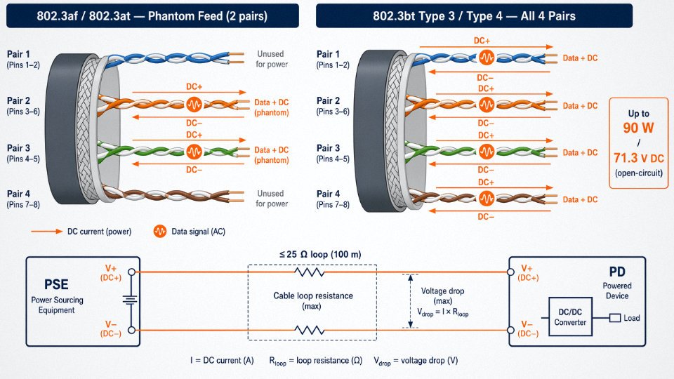
802.3af and 802.3at use what the standard calls the “phantom” method: the DC power rides on the same twisted pairs carrying data, superimposed as a common-mode signal. The data signals are differential, so they cancel out at the transformer; the DC doesn’t. It’s an elegant solution that required no extra pairs, which is why it worked on two-pair active installations.
802.3bt changed the math by adding the spare pairs (pairs 1 and 4 in TIA-568 numbering, typically blue and brown). Running all four pairs in parallel cuts the effective loop resistance roughly in half, reduces heat generation per pair, and is what makes 90 W delivery physically possible without requiring heavier-gauge cable. Both methods can be active simultaneously in a Type 3 or Type 4 switch.
The 71.3 V Open-Circuit Situation
Installation Warning — IEC 62368-1 Threshold: An 802.3bt Type 4 PSE port can sit at up to 71.3 V DC open-circuit before a PD handshake completes. IEC 62368-1 (which replaced IEC 60950-1) classifies anything above 60 V DC as a Class 2 energy source requiring additional safeguards. In practice this means patch panels and open-ended PoE++ ports in accessible areas — server rooms with rotating staff, factory floors, school IT closets — need clear labeling and, ideally, port shutdown policies when cables are unplugged. It’s not a dramatic shock hazard, but it’s above the threshold where the standard stops calling it “limited power.”
IEEE 802.3bt Type 4 open-circuit voltage can reach 71.3 V DC, placing it above the IEC 62368-1 Class 2 limit of 60 V DC.True
The 802.3bt standard specifies a maximum open-circuit voltage of 71.3 V at the PSE port for Type 4, and IEC 62368-1 sets the Class 2 DC voltage boundary at 60 V, confirmed in both the IEEE and IEC published standards.
Proprietary PoE and Why It Still Causes Problems
Before 802.3at ratified, Cisco shipped what it called “Cisco Inline Power” (later “Pre-Standard PoE”) at voltages and detection sequences that didn’t match the 802.3af negotiation protocol. Ubiquiti ran a similar proprietary scheme on certain 24 V passive PoE systems — no handshake at all, just constant voltage on the pairs regardless of what’s connected. Plug a 24 V passive PoE device into an 802.3at port, or vice versa, and you’re either starving the device or, in the worst case, applying voltage to equipment that wasn’t expecting it.
The cable itself usually survives. The end device sometimes doesn’t, and the failure mode is often a quiet one — degraded performance or reduced lifespan rather than an immediate dead port. On any project where you’re inheriting existing switching infrastructure, it’s worth auditing PSE firmware versions and port configurations before assuming the cable plant is the problem.
Cable Category and Construction: Which Ethernet Cables Are Rated to Handle PoE Voltage Safely
Not every cable that carries data is ready to carry power. That distinction matters far more than most procurement checklists acknowledge, and getting it wrong shows up as thermal degradation, excessive voltage drop at the powered device, or — in the worst case — insulation failure in a bundled ceiling conduit nobody opens for five years.
Category Ratings: Bandwidth Is Only Half the Story
TIA-568 and ISO/IEC 11801 define category ratings primarily around frequency performance — insertion loss ceilings, return loss, NEXT — but those same parameters indirectly constrain PoE suitability. Cat 5e is rated to 100 MHz and remains the minimum acceptable category for IEEE 802.3af/at deployments; it physically works for 802.3bt too, though you’re leaving headroom on the table. Cat 6 (250 MHz) tolerates higher-frequency signaling with lower insertion loss and is the practical minimum most experienced installers specify for new 802.3bt Type 3/Type 4 runs. Cat 6A at 500 MHz is genuinely the sweet spot for high-power PoE: its larger conductor cross-section and tighter manufacturing tolerances reduce resistive losses, and the augmented spec explicitly addresses alien crosstalk that becomes relevant at 10GBASE-T data rates running alongside PoE current.
Cat 7 and Cat 8 occupy a different tier. Cat 7 (600 MHz, S/FTP construction) and Cat 8 (2000 MHz, also S/FTP) are designed for data center and industrial backbone applications. They handle PoE without complaint electrically, but their stiff, individually-shielded pair construction can make field termination slower and costlier — worth it for a 30-meter server room spine, probably overkill for a 80-meter IP camera run in a warehouse.
Conductor Gauge: Where Voltage Drop and Heat Are Actually Created
DC resistance is where the physics gets unambiguous. For a 100 m horizontal cable run carrying 802.3bt Type 4 current, TIA-568 caps the DC loop resistance at 12.5 Ω per pair. Whether a given cable meets that ceiling depends almost entirely on conductor AWG.
| AWG | Approx. DC loop resistance, 100 m pair | Typical use case |
|---|---|---|
| 22 | ~5.8–6.5 Ω | Industrial, solid, high-power PoE |
| 23 | ~7.5–8.2 Ω | Cat 6A solid, standard horizontal |
| 24 | ~9.4–10.5 Ω | Cat 5e/6 solid, most common |
| 26 | ~15–17 Ω | Patch cords, short flex runs only |
Figures depend on conductor purity (bare copper vs. CCA), stranding, and exact length. CCA — copper-clad aluminum — will run roughly 55–60% higher resistance than solid bare copper at the same AWG. For PoE, CCA is genuinely problematic; the voltage drop penalty at 90 W loads can push a 26 AWG CCA cable well past the 12.5 Ω limit before you’ve even accounted for connector resistance.
AWG 26 copper-clad aluminum patch cables are unsuitable for IEEE 802.3bt Type 4 deployments beyond short runsTrue
CCA conductors have roughly 55–60% higher resistivity than solid bare copper. At AWG 26, DC loop resistance for a 100 m run can reach 15–17 Ω even in pure copper; CCA pushes this past 20 Ω, far exceeding the TIA-568 12.5 Ω ceiling and causing unacceptable voltage drop and heating under 90 W PoE loads.
Shielding and Thermal Behavior in Bundled Runs
This is the area that trips up even experienced facilities engineers. UTP cable dissipates resistive heat outward through the jacket and into surrounding air — in a loose conduit with good airflow, it manages reasonably well. Bunch 24 UTP cables together in a tight cable tray under 802.3bt four-pair loading, and temperature rise of 10–15 °C above ambient is realistic. That doesn’t sound catastrophic until you remember the ambient inside a crowded conduit in a sun-exposed rooftop plant room can already be 45–50 °C in summer.
F/UTP (overall foil, unshielded pairs) and S/FTP (braided outer shield plus individual pair foils) behave differently. The metallic layers conduct heat longitudinally along the cable, which sounds helpful but in a tightly bundled installation actually reduces radial heat dissipation — the bundle’s thermal resistance rises. ANSI/TIA-568.2-D Annex M provides derating curves that quantify how bundle count and fill factor force you to either reduce the current per pair or specify a higher-rated cable. In practice, most installers skip Annex M entirely and then wonder why PoE switches are throttling power after two years.
Jacket Material: PVC, LSZH, and Plenum FEP
Jacket choice affects both voltage withstand and building-code compliance. Standard PVC jackets are rated for in-wall use in most residential and light commercial applications; they soften around 60–75 °C depending on plasticizer content, which is relevant if you’re consistently operating near the thermal ceiling in a bundled tray. LSZH (low-smoke zero-halogen) jackets are mandatory in many European and Middle Eastern specifications for occupied buildings — they don’t produce corrosive halogen gases when burning, which matters enormously for data center equipment even if the cable itself survives. Electrically, LSZH jackets typically withstand 1000–2000 V AC dielectric test voltage, well above PoE operational levels.
Plenum-rated cables with FEP or low-smoke PVC jackets are required by NEC Article 800 in US air-handling spaces. FEP is dimensionally stable up to roughly 200 °C continuous, so thermal derating under PoE loads is a non-issue. The trade-off is cost — plenum cable typically runs 40–80% more per meter than riser-rated equivalents, depending on market conditions and order volume.
Matching Specification to Deployment
Jinda manufactures Cat 5e through Cat 8 cables with solid AWG 22, 23, and 24 conductor options, covering UTP, F/UTP, and S/FTP constructions, with PVC, LSZH, and plenum jacket variants available across categories. The production lines are built to ANSI/TIA-568 and IEC 61156 dimensional and electrical tolerances, which matters specifically for PoE applications where pair-to-pair resistance unbalance — not just average resistance — affects how current distributes across the four pairs in a 802.3bt Type 4 deployment. Unbalanced pairs mean uneven heating. It’s a specification detail that separates cables built for power delivery from cables built only for data.
Specify the wrong AWG or jacket for the installation environment, and you’ll discover it during a heat wave or a partial-load expansion, not during commissioning when everything looks fine.
Temperature Rise and Voltage Drop: The Engineering Calculations That Protect Your PoE Installation
Most PoE installations fail the voltage budget on paper before a single cable is pulled — the problem is that almost nobody does the paper calculation first.
The Voltage Drop Formula and Why It Bites at 100 Meters
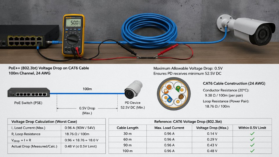
The fundamental relationship is straightforward: V_drop = I × R_loop, where R_loop = 2 × (resistance per meter × cable length). The factor of two is the part people forget — current travels out on one conductor and returns on the other, so you’re paying the resistive penalty twice.
Cat 6 AWG 23 copper conductor runs roughly 9.38 Ω per 100 m per conductor at 20 °C, giving a loop resistance of about 18.8 Ω for a 100 m horizontal run. Under IEEE 802.3bt Type 4 (PoE++), each powered pair carries approximately 1.73 A. Plug that in: V_drop = 1.73 A × 18.8 Ω ≈ 3.3 V per pair. Four pairs delivering power simultaneously each drop 3.3 V, so the powered device receives somewhere in the range of 50–54 V depending on the PSE output — still comfortably above the 802.3af minimum of 44 V in a clean, unloaded tray. That comfort margin evaporates fast once you add bundling heat.
Bundling Changes Everything: The TIA-568.2-D Annex M Derating Reality
A single cable in free air dissipates heat without much trouble. Pack 24 PoE cables into a cable tray or conduit and the thermal picture changes completely. ANSI/TIA-568.2-D Annex M establishes bundling derating guidelines: a bundle of 24 cables all carrying simultaneous PoE load can require current derating of up to 40% per conductor, or — if you need to maintain full current — a significant reduction in allowable run length to keep temperature rise within 10 °C of the cable’s rated operating temperature ceiling (typically 60 °C for standard PVC-jacketed horizontal cable, 75 °C for some plenum-rated constructions).
In practice this means a 100 m run that looks fine for a single cable may only be acceptable to about 60–70 m in a dense bundle before you breach the thermal limit. The exact cutoff depends on tray fill percentage, ambient temperature, whether adjacent cables are also under PoE load, and airflow through the tray. Seasonal effects matter too — a poorly ventilated ceiling plenum in summer runs 10–15 °C warmer than winter, and that shifts your entire operating point.
The Compounding Effect: Why Heat Makes Voltage Drop Worse
Copper resistance rises approximately 0.393% per °C. A bundle running 15 °C above ambient has conductors with roughly 6% higher resistance than your room-temperature calculation assumed. Feed that back into V_drop = I × R_loop and the drop per pair increases proportionally. In a worst-case scenario — dense bundle, high ambient, long run, Type 4 load — PD voltage can slide below 44 V, which is the 802.3af minimum. The powered device either underperforms or resets repeatedly. Maintenance chases the symptom for weeks before anyone pulls a thermal camera on the tray.
IEEE 802.3bt Type 4 guarantees at least 71.3 V at the PSE output, but cable resistance and bundling can push PD voltage below the 802.3af minimum 44 V in long, dense installations.True
The 802.3bt standard specifies PSE open-circuit voltage up to 71.3 V and a minimum PD voltage, but cable loop resistance and thermal derating in dense bundles create compounding voltage drop that the standard explicitly requires installers to account for through proper cable selection and run-length limits.
Mitigation: What Actually Works on the Floor
Cat 6A is the practical answer for high-density PoE. The larger AWG 23 conductor (same gauge as Cat 6 but tighter tolerances and typically better conductor concentricity) offers slightly lower DC resistance, and the larger overall cable diameter improves thermal mass and surface-area-to-volume ratio for heat dissipation. Shielded Cat 6A — F/UTP or U/FTP — performs better still in dense trays because the foil acts as a modest thermal spreader.
Beyond cable selection: keep tray fill below 40% for PoE-heavy runs, separate PoE and non-PoE cables where feasible, and specify perforated trays over solid-bottom trays to get airflow underneath. For high-density PoE panels — say, 48-port switches feeding IP cameras throughout a facility — active cable management with horizontal cable managers that allow spacing between bundles is worth the added cost.
Jinda’s technical support team provides free cable sizing and bundle derating calculations as part of its pre-sales engineering service for international customers, which is genuinely useful if you’re specifying a large run without an in-house cable engineer on staff. Getting those numbers checked before procurement is considerably cheaper than re-pulling 2,000 meters of undersized cable.
Voltage Isolation, Safety Standards, and Grounding Requirements for PoE Cable Runs
IEC 62368-1 and the Energy-Hazard Classification That Governs 802.3bt
IEC 62368-1 replaced IEC 60950-1 fully by 2022 and shifted the safety framework from a prescriptive “is it a power supply or IT equipment?” model to a physics-based energy-hazard classification. Under that model, a source is assessed by what it can actually do to a human body — not what category the product falls under. PoE at 802.3af/at (44–57 V DC) sits comfortably in the ES2 class, which is considered painful but not lethal under normal dry-skin contact. 802.3bt Type 4 at up to 71.3 V DC open-circuit bumps right against the ES2/ES3 boundary, and that matters.
It is still classified as a “limited-power source” under IEEE 802.3, which constrains the maximum available energy and limits fault current. But limited-power does not mean no-hazard. Installers working on live 802.3bt circuits in confined cable trays, or anyone probing a poorly terminated jack with wet hands, faces a meaningfully different risk than they would on a 48 V telecom pair. The practical consequence: 802.3bt installations in commercial buildings increasingly fall under the inspection scope of IEC 62368-1 annex requirements, and some jurisdictions are now requiring labeling on patch panels identifying PoE-capable ports. Worth confirming with your local AHJ before commissioning.
Insulation Voltage Ratings: Where the Real Risk Actually Lives
Standard PVC insulation on Category 5e through Category 8 cable is rated for 300 V AC rms or 300 V DC — well above the 71 V DC that 802.3bt delivers. So the cable insulation itself is not the limiting factor under normal steady-state conditions.
The problem is transients. A lightning strike 200 m away from a building can couple several kilovolts onto an outdoor cable run in milliseconds. Ground potential differences between two buildings on a large campus — especially where the electrical infrastructure was installed in stages across different decades — can add tens or even hundreds of volts of common-mode offset onto the cable shield or pairs. Under those transient conditions, the margin between 71 V nominal and 300 V rated insulation shrinks fast.
Standard Cat5e/6 PVC insulation at 300 V DC is adequate for steady-state 802.3bt PoE voltages but not for transient overvoltages in inter-building runs without surge protection.True
IEEE 802.3bt maximum open-circuit voltage is 71.3 V DC, which is well below the 300 V DC insulation rating of standard PVC-jacketed Ethernet cable. However, lightning-induced surges and ground potential differences in campus environments can produce transient voltages exceeding the insulation rating, requiring SPD protection on inter-building runs.
Shielded Cable Grounding: Single-Point, Both-End, and the Ground Loop Problem
ISO/IEC 14763-2 is the installation standard that governs structured cabling, and its guidance on shielded cable grounding is frequently misread. The textbook answer is single-point grounding — ground the shield at one end only, typically at the distribution frame — to prevent ground loop currents. That works well for short, intra-building runs.
On longer runs, or wherever two bonding points have different ground potentials (common in industrial plants, older campuses, any site with heavy motor loads), single-point grounding can leave the shield floating at the remote end, which reduces its effectiveness against high-frequency interference. Some installers ground both ends, which resolves the shielding problem but introduces a low-impedance loop. That loop can carry noise currents directly onto the cable, degrading the differential voltage margins that 1000BASE-T and 10GBASE-T depend on.
The practical resolution is equipotential bonding: bring both bonding points to the same ground reference before you connect the shield. In industrial settings this usually means running a dedicated grounding conductor between the two cabinets. It adds cost and takes time. Skip it and you will spend far more tracing intermittent link drops.
Surge Protective Devices for Outdoor and Inter-Building PoE Runs
Any PoE run that exits a building — rooftop cameras, parking lot access points, inter-building links — needs an SPD on both ends. The selection criteria matter more than most procurement specs acknowledge.
IEEE C62.42 defines the application classes, and for data/PoE circuits you need a device with a clamping voltage below 400 V (lower is better; aim for under 300 V if the device is available), a response time under 1 ns, and insertion loss below 0.5 dB across the cable’s operating frequency range. That last requirement eliminates a lot of cheap units. An SPD with 1–2 dB insertion loss on a 10GBASE-T link will cause marginal channels to fail, and the failure will look like a cable fault, not a protection device problem. Verify SPD performance with the cable category you are running — a device tested for Cat 6 may not meet insertion loss requirements for Cat 6A or Cat 8.
Response time is equally non-negotiable. A device rated at 5–10 ns may clip the peak of a fast lightning transient after the leading edge has already stressed the cable insulation and switch port.
Certifications That Should Appear on the Cable Datasheet
For any project with cross-border procurement or insurance requirements, the cable needs to carry relevant third-party certifications. UL Listing (or ETL for North America) confirms that the cable construction was tested by an independent lab — not just factory-self-declared. CE marking is mandatory for the European market. RoHS and REACH compliance matter wherever hazardous substance restrictions apply, which is most developed markets. KEMA certification is recognized across much of Europe for industrial applications.
A cable that carries only factory test reports and lacks third-party marks is a liability on a commercial or industrial project, regardless of how good the datasheet looks. Insist on documentation before procurement is finalized.
Industrial and Outdoor PoE Deployments: Voltage Stability Across Harsh Environments
Most PoE installations get planned at 20 °C on a clean desk. The cable ends up running through a logistics warehouse at +55 °C ambient, bundled with motor control cables, exposed to rain at one end and a forklift bay at the other. That gap between spec sheet and field reality is where PoE voltage problems live.
Temperature’s Direct Effect on Delivered Voltage
Copper resistance isn’t fixed. It rises roughly 0.393% per °C above 20 °C — that’s the standard temperature coefficient for annealed copper, and it’s not negligible at industrial temperature extremes. At +75 °C, a conductor’s resistance is approximately 15% higher than at the 20 °C baseline used in every datasheet calculation. On a 90 m Cat 6A run with 26 AWG conductors, that resistance increase can drop delivered PoE voltage by 3–5 V depending on load current and pair configuration. For 802.3af (44–57 V nominal), that margin might still be acceptable. For a device sitting right at its minimum input voltage, it isn’t.
Cold end of the range matters too, though differently. At −40 °C, resistance is lower and voltage delivery improves slightly — but elastomers in non-rated jackets become brittle, crimp connections crack under thermal cycling, and standard polyethylene insulation can develop micro-fractures that won’t show up until moisture ingresses. Specifying cable rated for a genuine −40 °C to +75 °C operating range isn’t conservative bureaucracy; it’s the difference between a five-year installation and an eighteen-month troubleshooting nightmare.
Mechanical Protection: Armor, Burial, and UV Resistance
Outdoor PoE runs need physical protection that indoor Cat 6A simply doesn’t provide. The main options each carry trade-offs that affect installation practice, not just cost.
Corrugated steel tape (CST) armor provides strong crush resistance and rodent protection, but it adds weight and stiffness — minimum bend radius typically increases to 8–10× the cable OD versus 4× for unarmored equivalents. Interlocked aluminum armor is more flexible and works well in conduit pull or cable tray, but doesn’t seal against moisture on its own. Direct-burial gel-filled cables flood the core with a water-blocking compound that prevents longitudinal water migration; they’re messy to terminate (you need to clean the gel off the conductors before connectorizing) but genuinely suited to below-grade runs where conduit isn’t practical. UV-stabilized HDPE or LLDPE jackets are non-negotiable for any exposed aerial or surface-mounted run — standard PVC yellows and cracks within a year or two of UV exposure, and jacket degradation is usually how moisture gets in.
EMI Environments and Shielding Specification
In factory settings near variable-frequency drives (VFDs), servo motor cables, or high-current bus bars, unshielded twisted pair is a liability. Induced common-mode noise from nearby power wiring can easily reach 1–3 V peak on an unshielded cable run — enough to push the receiver past its common-mode rejection limit and trip protection circuits, or corrupt packets in ways that look like a network switch problem rather than an EMI problem. S/FTP Cat 6A or Cat 7A with individual pair foils plus an overall braid provides the best combination of high-frequency shielding effectiveness and the mechanical robustness needed in industrial trays. The shield must be grounded at one end only for long runs to avoid ground loop currents; in practice, grounding at the PSE end is the cleaner choice in most plant layouts.
Worked Scenario: Warehouse Camera Network, 90 m Runs, 802.3bt Type 3
A distribution warehouse installs 24 outdoor IP cameras on the building perimeter, each requiring 802.3bt Type 3 PoE (up to 60 W, nominal 50–57 V at the PSE). Cable runs average 90 m, routed in a shared cable tray that also carries 480 V motor control wiring to dock leveler drives.
Cable selection here isn’t a simple category choice. The shared tray mandates shielded cable — S/FTP Cat 6A is the practical minimum, and Cat 7A S/FTP would be specified if the tray spacing from power cables is under roughly 300 mm. Armor is warranted for the exposed exterior sections. For voltage drop: at 20 °C, a 90 m Cat 6A run (23 AWG, ~8.2 Ω per pair at 100 m) gives a loop resistance around 7.4 Ω at 90 m per pair — well within the 12.5 Ω TIA-568 limit. At +55 °C summer ambient inside a metal tray, resistance climbs by about 14%, putting loop resistance around 8.4 Ω. At 1.0 A draw (60 W ÷ 57 V, worst case), voltage drop per pair is roughly 8.4 V, leaving approximately 48–49 V at the camera. That’s above the 802.3bt Type 3 minimum PD input of 42.5 V — but only just, without bundling derating applied.
IEEE 802.3bt Type 3 guarantees a minimum of 42.5 V at the powered device across a compliant 100 m horizontal cable run.True
IEEE 802.3bt specifies minimum PD input voltage of 42.5 V for Type 3 (Class 5/6) under worst-case conditions, with the PSE output at 50–57 V nominal and cable losses accounted for within the standard's 100 m channel model.
Bundling four or more cables in the tray adds thermal derating on top of that. The right answer for this installation is 23 AWG S/FTP Cat 6A with a UV-stabilized LLDPE jacket and corrugated steel tape armor on the exterior sections — a product class that Jinda’s armored outdoor Ethernet cable line is built around, with ratings validated across the full −40 °C to +75 °C industrial temperature range and shielding effectiveness tested against IEC 61156.
Cutting corners to plain Cat 6A UTP here wouldn’t cause instant failure. It would cause intermittent camera dropouts on hot afternoons that take two service calls to trace back to marginal voltage delivery. That’s the realistic consequence, and it’s expensive in a way that doesn’t show up on the original procurement quote.
Frequently Asked Questions About Ethernet Cable Voltage
Can I run PoE and data simultaneously on the same Ethernet cable without interference?
Yes, and this is actually one of the more elegant parts of the IEEE 802.3 design. PoE delivers power as either a DC offset or a low-frequency AC signal riding on the twisted pairs, while data travels as high-frequency differential signals — typically in the MHz to GHz range depending on the standard. The PHY (physical layer transceiver) at each end is transformer-coupled, which inherently blocks DC. The standard mandates that data circuitry reject the power component, so the two coexist without meaningful crosstalk under normal conditions.
In practice, the concern is rarely interference — it’s heat and voltage drop, which are covered in the thermal and drop calculations elsewhere in this article.
Is 48 V PoE dangerous to touch?
Under IEC 62368-1, voltages below 60 V DC fall into the PS2 (limited energy) classification and are not generally regarded as a lethal shock hazard under dry, intact-skin conditions. That said, “generally not lethal” is a low bar to set your safety culture around. Wet environments, abraded insulation, or a technician with a cut on their hand changes the risk profile meaningfully. Best practice is to treat all energized conductors with respect regardless of voltage class — de-energize before re-terminating, inspect insulation before pulling through conduit, and never assume a cable is dead because it looks dead.
IEEE 802.3bt Type 4 PoE operates at up to 71.3 V DC open-circuit at the PSE output, which exceeds the IEC 62368-1 PS2 threshold of 60 V DC.True
IEEE 802.3bt specifies a maximum open-circuit voltage of 71.3 V at the power-sourcing equipment, placing it in the PS2/PS3 boundary region. This is one reason proper insulation rating and installation practice matter more with 802.3bt than with earlier PoE generations.
What happens if I use Cat 5e cable for 802.3bt 90 W PoE?
This comes up more often than it should. Cat 5e typically uses AWG 24 conductors; Cat 6A typically uses AWG 23. That one AWG step translates to roughly 10–12% lower DC resistance per unit length — which matters a lot when you’re pushing four-pair power simultaneously over a 100 m bundled run. Under 802.3bt conditions, the combined voltage drop and thermal rise on AWG 24 cable can push pair temperatures 10–15 °C above ambient in a tight bundle, and voltage at the powered device end may drop below what the device needs to operate reliably. TIA-568 explicitly recommends Cat 6A or better for 802.3bt deployments. Using Cat 5e isn’t guaranteed to fail immediately, but you’re burning margin you may need when ambient temperature climbs in summer or when someone adds more cables to the same tray.
Can Ethernet cable carry higher voltages for other applications like Single-Pair Ethernet?
IEEE 802.3cg (10BASE-T1L) is worth knowing about if you work in industrial automation or process control. It runs 10 Mbit/s over a single twisted pair for distances up to roughly 1,000 m — far beyond standard Ethernet’s 100 m limit. The companion PoDL (Power over Data Line) standard can deliver up to 52 V DC and 50 W over that same single pair. The cable construction differs from conventional multi-pair structured cabling, and the voltage/distance combination demands careful attention to insulation rating and ground loop management, especially in environments with large potential differences between equipment.
Does cable length affect the voltage a PoE device actually receives?
Directly and predictably. Every meter of cable adds DC resistance, and resistance times current equals voltage lost before the powered device sees it. TIA-568’s 100 m horizontal run limit exists precisely because beyond that, you can no longer guarantee that insertion loss and resistive drop together stay within the bounds the standards define. A 100 m run of AWG 24 at full 802.3bt load can drop several volts — the exact figure depends on conductor temperature, bundle size, and actual current draw — leaving the PD with noticeably less headroom than a 30 m run would.
If your layout is pushing past 80 m, budget the voltage drop calculation before you pull cable. Fixing it after the fact usually means adding a midspan injector or rerouting, neither of which is cheap.
What voltage test do cable manufacturers perform before shipping?
Reputable manufacturers apply a hi-pot (high-potential dielectric withstand) test — typically somewhere in the 1,000–2,000 V AC range applied between conductors and between conductors and the shield or ground — to verify that insulation integrity is intact before the cable leaves the factory. This catches micro-defects in the insulation that would never show up in a continuity or resistance check but would fail under real operating voltage, especially after the cable has been pulled through conduit and bent around corners.
Jinda performs hi-pot testing as part of its 100% outgoing quality inspection on shielded and industrial-grade Ethernet cables, with test parameters documented on the quality certificate shipped with each drum. When you’re procuring cable for a PoE deployment — particularly 802.3bt or an outdoor industrial run — asking for the hi-pot test record is a reasonable and professional request. Any manufacturer worth working with should have it ready.
Specifying and Sourcing PoE-Ready Ethernet Cable for Large-Scale Projects: A Practical Checklist
By the time you’ve worked through voltage drop calculations and thermal bundling limits, the engineering is largely done. The harder problem, in practice, is translating that engineering into a procurement document that actually protects you — and then finding a supplier who can deliver against it consistently across a 50,000-meter order, not just a sample spool.
What Must Appear in the Specification Document
A PoE cable spec that just says “Cat6A, UTP” is almost useless for serious project work. At minimum, your procurement document needs to call out:
Cable category and channel rating — Cat5e, Cat6, Cat6A, or Cat8, with the target channel application (e.g., IEEE 802.3bt Type 3 or Type 4 PoE). Category alone doesn’t tell a supplier which end of the performance envelope you need.
Conductor AWG — for high-power PoE (60–90 W), 23 AWG solid bare copper is the practical baseline for 100 m runs. Accepting 24 AWG to save cost on a bundled IP camera installation is the kind of decision that creates warranty calls two summers later when the bundle runs hot.
Shielding configuration — UTP is fine for clean office environments; F-UTP (overall foil) adds alien crosstalk rejection in dense runs; S-FTP (braid plus individual pair foil) is warranted in industrial cable trays with heavy motor or VFD noise nearby. Specify it explicitly, because “shielded Cat6A” can mean different things to different factories.
Jacket material and flame rating — CM, CMR (riser), or CMP (plenum). For outdoor or industrial runs, specify UV-stabilized LLDPE or direct-burial gel-filled variants as applicable. Jacket compound chemistry matters for long-term insulation resistance, especially in installations that see seasonal temperature swings of 40°C or more.
DC resistance per 100 m — require a maximum figure aligned with TIA-568 limits (roughly ≤9.38 Ω/100 m for 24 AWG, ≤6.9 Ω/100 m for 23 AWG solid). This is the single parameter most directly tied to PoE voltage drop. If a supplier’s test report shows values clustered suspiciously near the limit on every reel, that’s worth a conversation.
Mutual capacitance and transmission parameters — call out insertion loss, NEXT, and ANEXT to the relevant TIA or ISO 11801 edition, and state which edition. The 2017 ISO 11801-1 revision tightened several parameters compared to earlier editions; don’t leave it ambiguous.
Third-Party Testing Is Non-Negotiable
Self-declared compliance is not compliance. For any bulk order going into a critical infrastructure, manufacturing, or public-safety application, require ETL Verified or UL Listed certification — or a recognized equivalent from an accredited body — with actual measured data, not pass/fail checkmarks. The test report should show insertion loss curves, NEXT and ANEXT margins, DC loop resistance, and dielectric withstand voltage results. A reputable manufacturer has these on file and can produce them without hesitation.
UL Listed and ETL Verified marks both require periodic factory audits and production sample testing, not just a one-time design certification.True
Both UL and ETL (Intertek) certification programs for cable include follow-up services with unannounced factory inspections and ongoing sample testing to maintain listing status, distinguishing them from a one-time self-declaration.
Supplier Evaluation Beyond the Data Sheet
Production capacity matters more than most buyers realize until they’re mid-project. Ask for monthly footage output on the specific category you’re ordering — not total plant capacity. Verify ISO 9001:2015 certification and, if your project is in a regulated sector, check whether the QMS scope actually covers the cable family you’re buying. Raw material traceability is increasingly a customer audit requirement: copper source documentation, insulation compound certification, and a current RoHS declaration plus REACH SVHC statement should be standard deliverables, not special requests.
Delivery track record is harder to verify but worth asking about directly. Request references from customers in your region, or at least in comparable logistics corridors. On-time delivery from a factory in Shandong to a port in, say, Rotterdam involves ocean freight scheduling, customs documentation, and container utilization planning — all of which break down differently than domestic supply.
Lead Times, Reel Logistics, and Import Documentation
Standard reel sizes for bulk Ethernet cable run 305 m (the North American pull-box standard), 500 m, and 1,000 m, with weight per reel varying roughly 8–35 kg depending on category and construction. For container planning on large orders, get accurate reel dimensions and gross weights early — a 40-foot container holds far fewer 1,000 m Cat6A S-FTP reels than the cubic volume alone suggests, once you account for reel diameter and stacking limits.
The documentation package for import should include a Certificate of Origin (for tariff preference purposes), full third-party test reports, RoHS declaration, REACH SVHC statement, and packing list with reel-level serial numbers if your project requires material traceability on installation.
Why Long-Term Supply Partnership Matters
For a 500-reel order, almost any factory will perform. The question is what happens on reel 501 when you need a non-standard AWG for a tight conduit fill, or a dual-rated CMR/outdoor jacket for a mixed indoor-outdoor run, or armoring for a direct-burial segment through a production facility.
Jinda’s five production bases across China — totaling 470,000 m² of manufacturing space — and in-house R&D capability mean custom specifications like non-standard conductor gauges, specialized jacket compounds, or armored variants can be engineered and produced without routing the order through a third-party subcontractor. Serving customers in more than 50 countries has also shaped a logistics and documentation process that handles the certificate and declaration requirements for most major import markets without back-and-forth. For project managers who’ve spent time chasing a missing RoHS declaration three weeks before a scheduled installation, that’s not a trivial point.