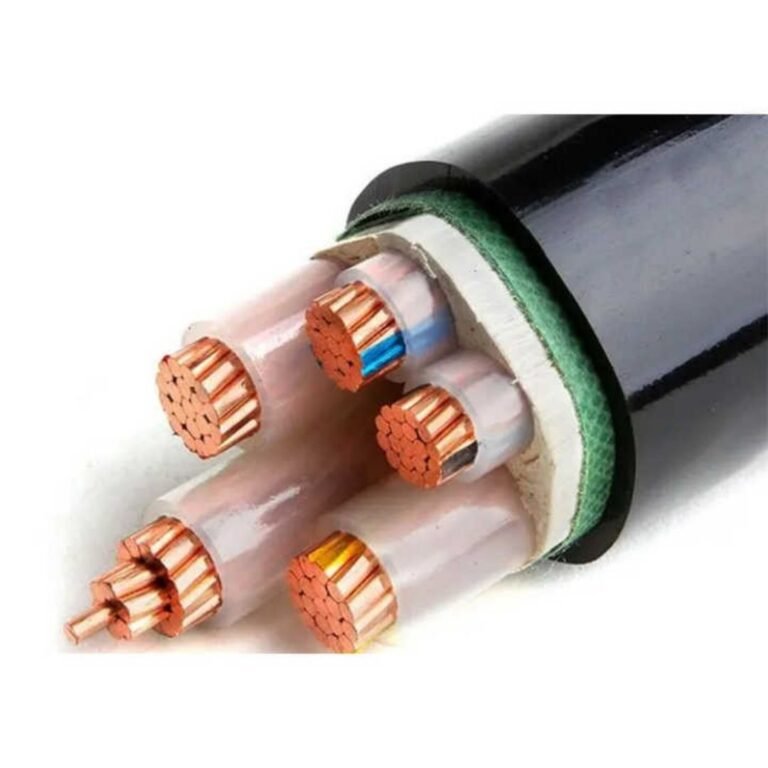
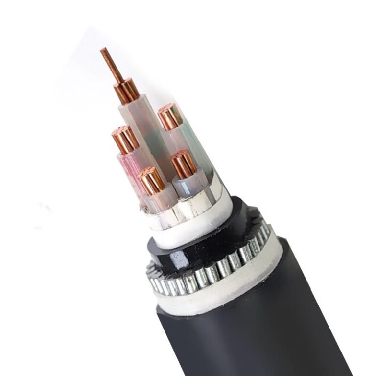
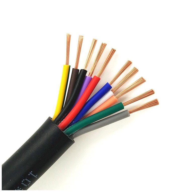
Ordering “Type 4 cable” from two different suppliers and assuming you’ll get the same product is a mistake that catches experienced procurement teams off guard. The conductor stranding is different, the insulation wall is thinner than your design spec, and the temperature rating printed on the reel doesn’t match what your protection relay was sized for. On a live project that means re-pulling cable, re-testing circuits, or running plant at derated capacity while you sort out a replacement order — none of which is cheap, and all of which was avoidable.
No, Type 4 cables are not all the same. The designation “Type 4” is defined differently under IEC 60502-1, BS 5467, AS/NZS 1158, SANS 1507, and several national variants, meaning conductor cross-sections, insulation thickness, sheathing material, and temperature ratings can vary by 10–30% between standards for nominally identical sizes. A cable labelled Type 4 from one country may be electrically and mechanically non-interchangeable with one from another.
What makes this genuinely tricky is that the differences aren’t always visible on the drum label, and a supplier quoting to your inquiry may be perfectly compliant with a standard — just not your standard. The gap between a 70°C PVC construction and a 90°C XLPE one, for instance, shifts continuous current-carrying capacity by up to 25% on the same conductor size, which is not a rounding error. Understanding exactly where the variation lives — and why it matters for your specific installation — is the only way to specify and procure with confidence.
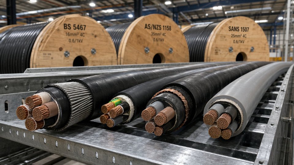
How Major Standards Define Type 4: IEC, BS, AS/NZS, and SANS Side by Side
If you’ve ever tried to cross-reference a Type 4 cable specification across two different project standards, you already know the frustration. The same two words mean genuinely different products depending on which document is sitting on the engineer’s desk. Working through each standard in turn is the only honest way to deal with this.
IEC 60502-1: The Framework Behind Many National Definitions
IEC 60502-1 doesn’t actually use the label “Type 4” anywhere in its text. What it does is define construction requirements for extruded solid dielectric insulated power cables rated from 1 kV up to 30 kV, covering conductor classes, insulation thickness, screen and sheath arrangements, and armour types in a modular, build-up fashion. The reason this matters for the Type 4 conversation is that most national standards bodies — particularly in Asia, the Middle East, and parts of Africa — have adopted IEC 60502-1 as their technical backbone and then applied their own type numbering on top. So when a procurement spec from a Southeast Asian contractor calls out “Type 4, 0.6/1 kV, XLPE insulated, PVC sheathed, multi-core,” they are almost certainly pointing at an IEC 60502-1-compliant cable with a local type label bolted on. The construction details — conductor stranding class, insulation thickness, oversheath colour and thickness — are drawn from IEC tables, but the designation itself is a national overlay.
This is actually a reasonably workable situation, provided the underlying IEC construction is clearly specified. The problem starts when engineers assume the type number alone is sufficient and skip the construction callout entirely.
BS 6346 and BS 5467: The British Legacy Interpretation
In British practice, Type 4 as it appears in older project documentation and legacy BS standards maps to steel wire armoured (SWA) cables insulated with either PVC (BS 6346) or XLPE (BS 5467), sheathed in PVC, and rated at 0.6/1 kV. These are fixed-wiring, multi-core power cables — the kind you’d pull into a cable tray in an industrial plant or a commercial substation fit-out. Conductor sizes run from roughly 1.5 mm² up to 630 mm², and the steel wire armour is the defining structural feature. Insulation thickness and sheath thickness are explicitly tabulated by conductor cross-section. XLPE-insulated variants under BS 5467 carry a 90°C conductor temperature rating, which gives a meaningful current-carrying capacity advantage over the 70°C PVC versions — typically 15–25% more continuous current for the same conductor size, depending on installation method and ambient temperature.
AS/NZS 1158: A Completely Different Animal
Here is where the confusion gets genuinely costly if you miss it. In Australian and New Zealand practice, Type 4 under AS/NZS 1158 refers to flexible trailing cables designed for mining equipment — draglines, continuous miners, shuttle cars. These are not fixed-wiring cables. They use EPR (ethylene propylene rubber) insulation and CSP (chlorosulphonated polyethylene) sheathing, and they’re rated at 1.9/3.3 kV or 3.6/6 kV. The mechanical construction — flexible stranding, robust outer sheath, resistance to trailing and flexing — is fundamentally different from a British SWA distribution cable. Specifying a BS-style Type 4 for an Australian mining trailing cable application, or vice versa, isn’t a minor paperwork error. It’s a safety-critical mismatch.
An AS/NZS 1158 Type 4 trailing cable and a BS 5467 Type 4 armoured cable are interchangeable for the same applicationFalse
They differ in voltage class, insulation material, mechanical flexibility, sheathing compound, and intended service conditions. AS/NZS 1158 Type 4 is rated 1.9/3.3 kV or 3.6/6 kV with EPR/CSP construction for dynamic mining service; BS 5467 Type 4 is a 0.6/1 kV fixed-wiring SWA cable. Using one in place of the other violates both standards and creates real safety risk.
SANS 1507: South Africa’s Take
SANS 1507 defines Type 4 as a 600/1000 V multi-core cable with PVC insulation and a PVC outer sheath — no armour as a defining requirement, though armoured variants exist. The definition sits closer to the British legacy interpretation than to the Australian mining cable world, but it’s not a direct copy. SANS specifies its own minimum insulation thickness values, which in some conductor sizes run slightly thicker than IEC equivalents, and the colour coding scheme for core identification follows South African practice, which differs from IEC 60446 in certain multi-core arrangements. In practice, South African industrial and infrastructure projects use SANS 1507 Type 4 for general building wiring, distribution boards, and light industrial fixed installations.
Side-by-Side Comparison
| Standard | Type 4 Scope | Voltage Rating | Insulation | Sheath | Armour | Typical Application |
|---|---|---|---|---|---|---|
| IEC 60502-1 (national adaptations) | Multi-core LV power cable, national type label applied over IEC construction | 0.6/1 kV | XLPE or PVC depending on local spec | PVC or HDPE | Optional (SWA or STA) | General industrial, infrastructure, utilities |
| BS 5467 / BS 6346 | SWA multi-core fixed-wiring cable | 0.6/1 kV | XLPE (BS 5467) or PVC (BS 6346) | PVC | Steel wire armour (defining feature) | Industrial plants, substation wiring, commercial infrastructure |
| AS/NZS 1158 | Flexible trailing cable for mobile mining equipment | 1.9/3.3 kV or 3.6/6 kV | EPR | CSP | None (flexibility-critical construction) | Underground and surface mining equipment |
| SANS 1507 | Multi-core PVC fixed-wiring cable | 600/1000 V | PVC | PVC | Optional | Building wiring, light industrial fixed installations, South African infrastructure projects |
The table makes the core problem concrete: voltage class alone varies from 0.6/1 kV up to 3.6/6 kV across these four regimes. Anyone sourcing “Type 4 cable” off a purchase order that names only the designation — without the governing standard — is genuinely flying blind.
Conductor Construction Differences: Stranding Classes, Cross-Sections, and Conductor Material
The conductor is where two cables with identical names start to diverge in ways that actually matter on the plant floor. A 35 mm² four-core cable called “Type 4” by a UK distributor and another called “Type 4” by an Australian mining supplier are not the same product — and if you substitute one for the other without checking the conductor class, you may not find out until you get premature termination failures or an unexpected voltage drop at the end of a 400-metre run.
IEC 60228 Conductor Classes and What Each Standard Demands
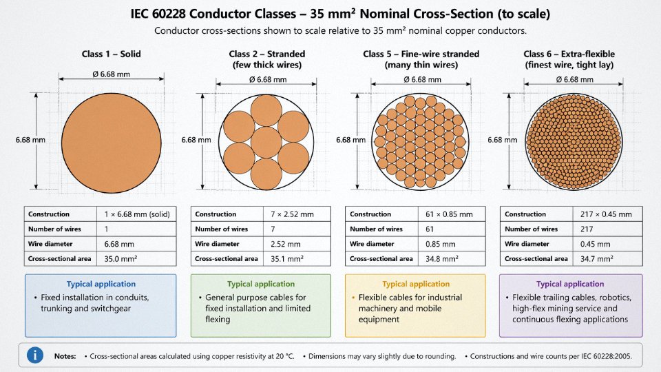
IEC 60228 defines four principal conductor classes relevant here. Class 1 is solid wire — essentially never appropriate for what most engineers mean by Type 4. Class 2 is stranded but relatively coarse, with fewer, thicker wires; it handles fixed installation well and terminates cleanly into compression lugs. Class 5 is fine-wire stranded, intended for flexible applications. Class 6 goes further — extra-flexible, tighter lay, finer gauge wires — and is used where repeated mechanical flexing is expected over the cable’s life.
Here is where the divergence begins. BS 5467-derived Type 4 multicore cables for UK distribution switchgear applications are typically built to Class 2 stranding. That works perfectly for static panel wiring. AS/NZS mining Type 4 trailing cables, on the other hand, routinely specify Class 5 or even Class 6 conductors because the cable moves — dragged across the floor, wound onto a drum, bent over sheaves dozens of times per shift. Specifying a Class 2 conductor in that environment is a straightforward path to wire fatigue cracking inside the lug, usually invisible until you measure insulation resistance and get a surprise.
Cross-Section Ranges and Application-Driven Sizing
The available cross-section range is itself application-driven. UK legacy Type 4 distribution cables are routinely stocked from 1.5 mm² up to 300 mm², covering everything from control wiring through medium-distribution feeders. The Australian and South African mining equivalents are generally specified starting at 16 mm² per phase — often up to 185 mm² — because the use case is high-current trailing cable feeding mobile mining equipment, not low-current panel wiring. You are unlikely to find a 2.5 mm² AS/NZS mining trailing cable; the application simply does not call for it.
Copper Versus Aluminium: What Each Standard Actually Permits
AS/NZS mining-type Type 4 trailing cables require copper conductors only and do not permit aluminium regardless of cross-section size.True
AS/NZS 1600 and related mining cable standards mandate copper for flexible trailing cables due to aluminium's inferior flex-fatigue resistance and lower fault current tolerance in mobile equipment applications. Aluminium conductors are brittle under repeated bending and are not suitable for Class 5 or Class 6 constructions in high-flex service.
Some IEC-mapped Type 4 constructions permit aluminium conductors above 16 mm², which keeps material cost down for fixed-installation distribution cables — aluminium at that size is a legitimate engineering choice where the cable does not move and terminations are properly torqued with bimetallic lugs. The flexibility penalty is irrelevant if the cable sits in a tray for thirty years. But in trailing cable service, aluminium’s flex-fatigue performance is genuinely poor; it work-hardens and cracks under repeated bending in a way that copper simply does not.
How Conductor Class Affects Real Electrical Performance
The resistance difference between conductor classes is small but not negligible on long runs. A 35 mm² Class 2 copper conductor will typically measure around 0.524 Ω/km at 20°C; the same nominal cross-section in Class 5 stranding usually comes in slightly higher, roughly 0.532 Ω/km, because fine-wire stranding introduces a marginally longer effective conductor path through the helical lay. On a 50-metre run that difference is academic. On a 400-metre trailing cable supplying a continuous miner, it feeds directly into your voltage drop calculation and your protection relay settings.
What You Cannot See in the Finished Cable
Strand compaction ratio, individual wire diameter tolerance, and lay length are manufacturing variables that are invisible once the cable is insulated. A conductor built with undersized wires to meet nominal cross-section on weight alone — without meeting the actual wire count and geometry specified in the standard — will terminate poorly, particularly in ferruled or compression terminations, and will fatigue faster in flexible service. Surface oxidation on individual wires, sometimes a seasonal problem in humid coastal manufacturing environments, reduces conductivity incrementally and accelerates corrosion inside the lug over time. None of this shows up on a cross-section measurement at goods receipt. It shows up eighteen months later as a warm termination or a nuisance trip.
This is why conductor construction specs — class, wire count, wire diameter, and surface treatment — belong in the purchasing specification, not just the conductor cross-section and voltage rating.
Insulation and Sheathing Material Variations: PVC, XLPE, EPR, and CSP Explained
The conductor inside a Type 4 cable gets most of the engineering attention, but the insulation and sheathing system is where the real differentiation lives — and where substitution errors cause the most damage.
PVC Insulation: The Legacy Baseline
Standard PVC insulation remains the dominant material in SANS 1507 Type 4 cables and in older BS 5467-era stock still circulating in distribution. The conductor temperature rating sits at 70°C, which sounds conservative until you realize that sustained operation above roughly 80°C causes the compound to soften progressively, which eventually leads to deformation under mechanical load and — in multi-core arrangements — tracking between conductors. For a 6 mm² conductor at 0.6/1 kV, IEC 60502-1 specifies 1.0 mm insulation wall thickness. That dimension matters: under-specified wall thickness from a non-compliant manufacturer drops dielectric withstand, full stop.
PVC performs well in fixed building wiring and civil infrastructure where temperatures are predictable and chemical exposure is minimal. The problem is oil and solvents. PVC swells and softens in hydrocarbon environments, which is why you will occasionally pull a supposedly serviceable PVC-insulated cable out of a pump station cable tray and find the insulation has turned sticky and cracked. Good for a substation cable duct. Not for a refinery.
XLPE: The Industrial Workhorse
Cross-linked polyethylene insulation has largely displaced PVC in new IEC 60502-1 and modern BS 7671-aligned Type 4 installations. The cross-linking process builds a three-dimensional polymer network that resists thermal deformation under sustained load — a fundamentally different failure mode compared to PVC, which simply softens. Conductor temperature rating rises to 90°C, and the practical consequence of that 20°C gap is significant: for the same conductor cross-section, XLPE-insulated cable carries roughly 20–25% more current continuously, depending on installation method and ambient temperature. In a project where conduit fill is tight, that can be the difference between a 35 mm² and a 50 mm² cable selection, which compounds through every joint, termination, and switchgear lug.
XLPE also handles moisture ingress better than PVC and tolerates a wider range of chemicals. For outdoor infrastructure, buried direct, or industrial plant environments, it is usually the right choice unless there is a specific flexibility requirement.
EPR: When the Cable Has to Move
Ethylene propylene rubber insulation appears in a specific and non-negotiable context: AS/NZS trailing cables used in mining. The reason is purely mechanical and thermal combined. EPR remains flexible at temperatures down to around -40°C, which matters in open-cut mining operations in cold climates where a PVC or XLPE cable would stiffen and crack at the bend points during winter startup. EPR also handles ozone and UV exposure without surface degradation — both real concerns for a cable lying on a haul road surface.
The 90°C conductor temperature rating matches XLPE on thermal performance, but EPR earns its place through flex-cycle fatigue resistance. A mining trailing cable may flex through tens of thousands of cycles over its service life. XLPE, despite its thermal performance, will eventually crack under repeated mechanical bending. EPR simply does not.
PVC Sheath Versus CSP Sheath: A Difference That Matters Enormously
This is where substitution errors become genuinely dangerous. Both PVC-sheathed cables and CSP (chlorosulfonated polyethylene, sometimes called Hypalon) sheathed cables appear under the Type 4 designation across different standards — yet their mechanical properties are in a different class entirely.
CSP offers abrasion resistance roughly three to five times greater than standard PVC compound, depending on the specific formulation and the test method used. In a mining environment where the cable is being dragged across rock surfaces and run over by equipment, that difference is not marginal. CSP also resists oils, diesel, and hydraulic fluid contact far better than PVC, and its flame-retardant performance in a confined underground heading is superior.
AS/NZS mandates CSP sheathing for trailing cables precisely because field experience showed PVC sheaths failing prematurely under those mechanical demands.
A PVC/PVC Type 4 cable is an acceptable substitute for a CSP/EPR Type 4 cable in a mining trailing application if both meet the same voltage rating.False
Voltage rating is only one parameter. AS/NZS trailing cable requirements specify EPR insulation and CSP sheathing because of flex-cycle performance, low-temperature flexibility, and abrasion resistance — none of which PVC/PVC construction meets. Substituting on the basis of shared 'Type 4' labelling ignores the mechanical and thermal requirements that define fitness for purpose in that application, and will typically void the cable manufacturer's warranty and potentially breach site safety compliance.
A procurement manager sourcing replacement trailing cable for a surface mining operation who specifies only “Type 4, 6 mm², 0.6/1 kV” without specifying EPR insulation and CSP sheathing may receive a compliant-looking PVC/PVC cable. It will pass a voltage test. It will fail in service — usually at a bend point, usually within one season, and potentially with a fault to ground that the trailing cable management system has to catch. That is an avoidable problem, and the fix is two extra lines on the purchase specification.
Armour, Screening, and Core Identification: The Variables Nobody Mentions in the Spec Sheet
The spec sheet usually tells you conductor size, voltage rating, and insulation material. What it rarely tells you — and what causes real problems during installation and commissioning — is how the cable is armoured, how the earth conductor is arranged, and what colour code the cores use. Two cables both stamped “Type 4” can differ on all three counts.
Armour Type and Why the Choice Matters More Than People Expect
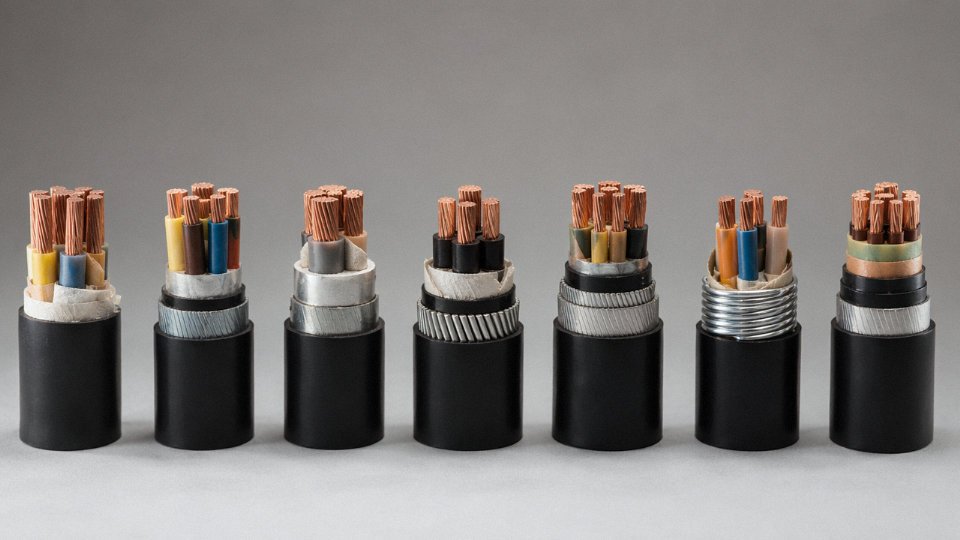
Steel wire armour (SWA) is the workhorse for buried multicore cables and fixed duct installations. It handles mechanical impact well and, under IEC 60502-1 and BS 5467 constructions, the armour itself is frequently used as the protective conductor — meaning the armour carries fault current back to the source. That works fine in multicore cables because the magnetic fields from balanced conductors effectively cancel each other out inside the armour. Run SWA on a single-core AC cable, though, and you induce circulating eddy currents in the steel that can get bad enough to overheat the sheath and cut continuous current capacity by a meaningful margin — sometimes 15–20% depending on cable size and load factor. For single-core installations, aluminium wire armour (AWA) is the correct call precisely because aluminium’s lower permeability breaks the eddy current loop.
Steel tape armour (STA) shows up more often in lightly loaded, protected-route installations where the priority is radial crush resistance rather than tensile pull-through strength. It is thinner, cheaper, and offers less mechanical protection than SWA when the cable is pulled under real tension through conduit.
The variable most procurement managers miss: flexible trailing cables used in mining draglines, mobile plant, and reeling systems cannot be SWA armoured at all. A rigid steel wire braid will crack under repeated flexing, and AS/NZS Type 4 mining designs typically specify flexible copper braid or textile braid over the cores instead. If you order an SWA version for a trailing application, you will see armour wire fractures within months. That is not a warranty argument you want to have.
Earth Core and ECC Arrangements: Not All Earths Are Equal
UK and IEC distribution-type Type 4 cables often include a reduced-section earth core — sized to handle fault current for the clearance time of upstream protection, not continuous load current. In many constructions the armour is the protective conductor, which simplifies installation but requires the electrician to ensure a low-resistance armour termination at both ends using proper glands. Skip that step and you have a high-impedance earth path that will not trip a standard overcurrent device fast enough during a ground fault.
AS/NZS mining Type 4 cables take a more explicit approach. They integrate a full-size earth continuity conductor (ECC) and sometimes a separate pilot core into the cable construction. The pilot core is there specifically for continuous earth fault loop impedance monitoring — underground mining regulations in Australia require that the earth circuit be monitored in real time, so a broken ECC trips the system before a fault becomes a fatality. Substituting a standard IEC Type 4 cable in that application because it is “equivalent” is a compliance failure and a safety risk.
In AS/NZS mining Type 4 cable applications, substituting a standard IEC multicore cable without an integrated ECC and pilot core does not meet underground mining earth fault protection requirements.True
Australian and New Zealand underground mining regulations require continuous earth fault loop impedance monitoring via a dedicated pilot core. Standard IEC 60502-1 multicore cables do not include this feature by design, making them non-compliant substitutes regardless of conductor size or voltage rating match.
Core Identification Colour Codes: A Termination Risk That Is Easy to Miss
IEC 60446 specifies brown, black, and grey for phase conductors, blue for neutral, and green/yellow for protective earth. That is the system most European and export-market cables follow. AS/NZS legacy designs used red, white (or yellow), and blue for phases — and some older plant in Australian mines still wires against that convention. SANS cables for southern African markets use their own colour assignments. If your maintenance electrician terminates a replacement cable by colour habit rather than checking the wiring diagram, the phase-to-neutral identification error can cause equipment damage or arc flash exposure on energisation.
This is not a theoretical concern. It comes up whenever a European-manufactured cable replaces a locally sourced one on a retrofit job without a full termination review. A cable labelled Type 4 from two different supply chains may arrive with completely incompatible core colours.
Screening for VSD and Instrumentation Applications
Some manufacturers offer screened Type 4 variants — usually a copper tape screen or braided copper screen over the assembled cores — for variable speed drive (VSD) feeders or sensitive instrumentation runs. The screen provides a return path for high-frequency conducted emissions and reduces electromagnetic interference pickup. Whether you need it depends heavily on cable length, the switching frequency of the drive, and whether the installation runs parallel to signal cables. For a 10-metre motor feeder in a steel cabinet, screening is mostly unnecessary cost. For a 150-metre VSD feeder running along a cable tray next to 4–20 mA instrument loops, skipping it can result in persistent measurement noise that is genuinely difficult to diagnose after commissioning.
Copper tape screens are cheaper and adequate for moderate shielding needs. Braided screens offer better coverage at higher frequencies and handle the mechanical stress of installation better, but they add cost and diameter.
Jinda’s Production Approach
Jinda manufactures both armoured and unarmoured Type 4 equivalents — SWA, STA, and unarmoured constructions — across its five production bases in China, covering IEC 60502-1 and BS-aligned specifications as well as custom project requirements. Full traceability runs from the conductor drawing stage through insulation extrusion and all the way to finished cable type testing, which matters when a procurement manager needs documentation for a project specification audit or a customs inspection in a regulated market. Core identification, armour type, and ECC configuration can be specified at order stage for project-specific builds rather than treated as fixed product parameters.
Voltage Rating and Testing Protocols: Where the 0.6/1 kV and 1.9/3.3 kV Gap Creates Real Risk
The U₀/U notation is one of those things that looks self-explanatory until someone gets it wrong. U₀ is the rated voltage phase-to-earth; U is the rated voltage phase-to-phase. So a cable marked 0.6/1 kV is designed for 600 V to earth and 1,000 V between phases — standard low-voltage distribution. A mining trailing cable rated 1.9/3.3 kV sees nearly three times the phase-to-earth stress. Even if both cables carry the same conductor cross-section — say, 35 mm² copper — the insulation wall thickness on the 1.9/3.3 kV construction will typically be 40–60% greater, because the electric field gradient the insulation must withstand scales with voltage, not conductor size. At 3.6/6 kV, the wall thickens further still. The conductor is doing the same job; the insulation is doing an entirely different one.
What IEC 60502-1 Type Tests Actually Confirm — and What They Don’t
IEC 60502-1 covers 0.6/1 kV cables and its test regime is built around that rating. The high-voltage type test applies 3.5 kV AC for 5 minutes on a completed cable sample. Routine production testing typically runs at 3.5 kV as well, though some manufacturers run it at 4 kV for internal quality reasons. The test suite also covers conductor DC resistance (confirming cross-section and material), insulation resistance after immersion, partial discharge for XLPE constructions (usually a 10 pC limit at 1.73 × U₀), and mechanical tests — elongation at break, tensile strength, hot set for XLPE.
Here is the critical point: passing every one of those tests at 0.6/1 kV level tells you nothing about how that cable behaves at 3.3 kV. The test voltages were chosen specifically for a 1 kV system. A cable that clears 3.5 kV for five minutes may fail catastrophically at sustained 3.3 kV phase-to-phase if the insulation wall was dimensioned for a lower field gradient.
Mining Trailing Cable Testing Is a Different Discipline Entirely
AS/NZS 1125 — the standard governing flexible cables used in Australian and New Zealand mining — applies substantially more rigorous electrical tests. For mining trailing cables, high-voltage withstand tests commonly reach 10 kV AC held for 15 minutes, and impulse withstand testing (simulating switching transients and lightning-induced surges) may also be required depending on construction class. The impulse test exposes the cable to a fast-rise voltage spike, typically 1.2/50 µs waveform, that a slow AC soak test simply cannot replicate. These requirements exist because underground mining drives run long trailing cable runs, operate in wet and abraded conditions, and are frequently switched under load — all conditions that generate transient overvoltages well above the nominal system voltage.
A standard IEC 60502-1 Type 4 distribution cable has never seen any of those tests. The two cables may share a designation and an identical conductor, but their qualification histories are completely different.
How Insulation Failure Actually Progresses in a Misapplied Cable
The failure mode is not sudden puncture. It is slower and in some ways worse. When a 0.6/1 kV Type 4 cable is energised on a 3.3 kV system, the electric field across the insulation wall exceeds its designed gradient from the first moment of operation. In PVC, this accelerates plasticiser migration and micro-cracking. In XLPE, the process is electrical treeing — tiny ionised channels propagate through the dielectric, branching outward from voids or contaminants. Neither process is visible during normal rounds. The cable passes insulation resistance tests with a hand-held megger for weeks or months, then fails during a load surge or a wet shift. Dielectric breakdown at 3.3 kV in a confined trailing cable arrangement releases enough energy to ignite jacket material. In mining environments, that consequence is obvious.
Rough field experience suggests accelerated failure timelines of 3–18 months in such misapplications, depending on ambient temperature, moisture ingress, and how frequently the cable is flexed. Drier, cooler, static installations last longer before failing — which is arguably worse, because it gives false confidence.
A cable that passes IEC 60502-1 high-voltage testing at 3.5 kV AC is qualified for use on a 3.3 kV mining system.False
IEC 60502-1 governs 0.6/1 kV cables. Its 3.5 kV test voltage is a proof test scaled to the 1 kV rating, not a qualification for 3.3 kV service. Mining cable voltage classes require separate standards, thicker insulation walls, and substantially more rigorous type and routine test regimes such as those in AS/NZS 1125 or IEC 60502-2.
Reading a Cable Drum Label Before You Accept the Delivery
The drum label is where mismatches get caught — or missed. At minimum, confirm these fields before the cable leaves goods-in:
| Label Field | What to Check | Red Flag |
|---|---|---|
| Rated voltage (U₀/U) | Matches system voltage class | “0.6/1 kV” on a 3.3 kV drawing |
| Standard reference | IEC 60502-1, AS/NZS 1125, BS 6708, etc. | Missing or vague (e.g. “meets IEC”) |
| Insulation material code | PVC, XLPE, EPR — matches spec | “PVC” where EPR trailing cable specified |
| Conductor class | Class 2 (fixed), Class 5/6 (flexible) | Class 2 on a mining trailing cable application |
| Test certificate origin | Country-specific IECEE CB scheme or local authority | Self-declared only, no third-party cert |
The voltage designation sits right at the top of the drum label in most constructions, but procurement teams under schedule pressure sometimes verify cross-section and conductor material and stop there. That is exactly how a 0.6/1 kV Type 4 ends up on a 3.3 kV drive. It fits the conduit, the lugs crimp correctly, the conductor resistance checks out — and the insulation problem will not show up until it matters most.
How to Specify the Right Type 4 Cable for Your Project: A Step-by-Step Selection Framework
Getting this right before purchase order stage saves far more than it costs. A wrong specification on a 500-metre buried feeder run isn’t a paperwork problem — it’s a re-excavation, a project delay, and sometimes an insurance dispute. Here’s a practical framework that works across international projects.
Step 1 — Identify the Governing Standard for Your Jurisdiction
This sounds obvious. It isn’t, especially on projects with mixed funding, international EPC contractors, or equipment supplied from multiple countries.
The primary standards authorities by market: IEC 60502-1 covers most of continental Europe, China, Southeast Asia, and the Middle East. BS 5467 and BS 6724 remain mandatory for UK projects and many legacy Commonwealth contracts in East Africa and South Asia. AS/NZS 1158 governs Australia and New Zealand. SANS 1507 is the reference for South Africa. France has NF C 32-100 series requirements that sit alongside IEC but add specific sheath and marking requirements. German projects typically require compliance with VDE 0276, which diverges from IEC on test voltages and sheath hardness.
Current editions matter. Standards get revised, and the revision can change insulation thickness tables by a meaningful margin. Obtain the current edition directly from the issuing body — IEC webstore, BSI Knowledge, SAI Global for AS/NZS, SABS for SANS. Don’t rely on a copy your colleague emailed five years ago.
Step 2 — Define the Application Class
Voltage rating alone doesn’t determine which Type 4 construction you need. A 0.6/1 kV four-core cable going into a direct-buried trench needs SWA or DSTA armour, a robust outer sheath rated for soil contact, and possibly bedding material between armour and insulation depending on the soil corrosivity classification. The same electrical rating in a cable management tray inside a clean, dry substation needs none of that, and over-specifying adds cost and installation weight without any performance benefit.
Fixed buried installation, fixed above-ground trunking, exposed outdoor (UV-rated sheath required), flexible trailing use (higher stranding class, abrasion-resistant sheath), mining and quarrying (often requiring CSP or ERP sheath per site safety regulations), and marine or offshore (halogen-free, flame-retardant requirements under IEC 60092 or equivalent) — each of these drives a materially different construction even within a single conductor size and voltage rating.
Step 3 — Confirm Conductor Cross-Section Through Load Calculation
The core calculation: load current (A) = rated power (kW) ÷ (√3 × voltage (kV) × power factor). That gives you the design current. Then apply derating factors: grouping correction (typically 0.7–0.8 for three circuits in trefoil), ambient temperature correction, and installation method factor per IEC 60364-5-52 or its national equivalent.
A 35 mm² Class 2 copper XLPE Type 4 cable in free air at 30°C runs roughly 169 A under IEC reference method E. Group it in trefoil with two other loaded circuits and that figure drops to somewhere around 127 A — a 25% reduction from a single parameter change. Undersizing at this stage because someone skipped the grouping factor is one of the more common causes of insulation degradation in plant cable installations, and it tends to show up gradually rather than immediately.
Step 4 — Write the Cable Specification String Correctly
A vague purchase order reading “Type 4, 35 mm², 4-core” will generate non-conforming deliveries. Different suppliers in different countries will each fill in the blanks using their local standard.
Write the full designation instead: 4-core 35 mm² Class 2 stranded copper conductor, XLPE insulated, SWA armoured, PVC oversheathed, 0.6/1 kV, per IEC 60502-1, cores identified by colour per HD 308 S2. That string removes almost every major ambiguity — conductor class, insulation material, armour type, voltage rating, governing standard, and core identification system.
A complete IEC 60502-1 cable designation string specifying conductor class, insulation material, armour type, and voltage rating prevents the majority of specification disputes on international procurement orders.True
Each parameter in a properly written designation maps to a testable requirement in the standard, leaving no room for a supplier to substitute materials based on their local practice or default construction.
Step 5 — Request Third-Party Test Certificates and FAT Data
A manufacturer’s own test report is useful context. It is not sufficient for safety-critical or high-value procurement.
Third-party type approval from KEMA, CESI, Bureau Veritas, or SGS confirms that a specific cable construction — with defined materials, dimensions, and manufacturing process — was independently tested against the stated standard. Critically, the certificate should reference the specific standard edition and the cable type designation exactly as you specified it. A type approval certificate for a PVC-insulated variant doesn’t cover XLPE construction, even if the conductor and armour are identical.
Factory acceptance testing (FAT) — conductor resistance measurement, high-voltage withstand test, insulation resistance, and dimensional checks — should be witnessed or at minimum certified by an independent inspector before shipment. For large orders, on-site inspection pays for itself.
Jinda’s in-house engineering team works directly with customers to map project specifications to the correct construction, issue dimensional and material data sheets, and coordinate third-party inspection at the factory prior to shipment — which matters most when lead times are tight and re-ordering isn’t an option.
Frequently Asked Questions About Type 4 Cable Differences
These questions come up repeatedly — from procurement desks, from site electricians holding two cables that look identical but aren’t, and from engineers who’ve inherited a spec written for a different continent. The answers below are direct.
Can I use a European Type 4 cable (0.6/1 kV, PVC/SWA) as a direct replacement for an Australian mining trailing cable?
No. Full stop. The two cables share a name and roughly similar cross-sections, but almost nothing else. A European PVC/SWA construction under IEC 60502-1 uses Class 2 (fixed-wiring) stranding, PVC insulation rated to 70°C, and a steel wire armour designed for mechanical protection in buried or conduit applications. An Australian mining trailing cable under AS/NZS 1158 requires Class 5 flexible stranding, EPR insulation, a CSP outer sheath that resists oil, flex fatigue, and ozone, plus a dedicated earth continuity conductor (ECC) sized to carry fault current through the trailing length.
Fit the European cable to a mining trailing application and you’re looking at conductor fatigue cracking within weeks, sheath splitting under repeated flexing, and — critically — a missing or undersized ECC that cannot clear a ground fault fast enough to protect the operator. That’s not a marginal technical deviation. It’s a breach of AS/NZS 1158 and a genuine electrocution risk.
Does a higher conductor cross-section automatically mean better cable?
No, and this assumption catches buyers out more often than you’d expect. A 50 mm² cable with loosely compacted Class 2 stranding, thin insulation walls at the low end of the standard’s tolerance band, and a borderline PVC compound can perform worse under short-circuit and sustained overload conditions than a properly manufactured 35 mm² XLPE cable. Cross-section is one variable. Insulation grade, conductor class, compaction quality, and standard compliance all sit alongside it. Evaluate the full construction, not just the conductor size on the drum label.
A larger conductor cross-section always means a higher-rated or higher-quality Type 4 cable.False
Cross-section determines ampacity for a given installation method, but cable quality and performance under fault or flexing conditions depend equally on insulation grade, conductor class, compaction, and the manufacturing standard applied. A poorly made large cable can fail faster than a well-made smaller one.
How do I verify that an overseas Type 4 cable actually meets my specification?
Start with the type test report — not a generic certificate, but a report that cites the specific standard revision you’ve ordered against and shows test values, not just pass/fail stamps. Check whether the samples were pulled from your production batch or were pre-made qualification samples; the latter tells you almost nothing about what’s on your drums. Get a photograph of every drum label before shipment — the label must show voltage rating, standard reference, conductor cross-section, insulation material, and manufacturer details in a traceable format. For large or safety-critical orders, a pre-shipment inspection by a recognised third-party body (SGS, Bureau Veritas, and similar) at the factory is worth the cost, typically a small fraction of the cable value on any order above a few thousand metres.
Is XLPE always the better choice over PVC?
Usually, yes — for outdoor industrial use, XLPE’s 90°C rating versus PVC’s 70°C translates to roughly 15–25% more continuous current-carrying capacity from the same conductor, and service life in UV-exposed outdoor conditions runs noticeably longer. But “always” is too strong. For short fixed indoor runs at low ambient temperatures, PVC is cheaper and in the field it strips faster and re-terminates more cleanly. Maintenance crews doing frequent joint work on panel wiring tend to prefer PVC for that reason alone. Pick the material against the actual operating environment and re-termination frequency, not a blanket rule.
What service life difference should I expect between PVC and XLPE outdoors?
In outdoor installations with UV exposure and seasonal temperature cycling, PVC insulation typically shows embrittlement, surface crazing, and eventually cracking somewhere in the 15–20 year range, depending on UV intensity and whether the jacket compound includes adequate stabiliser loading. XLPE in equivalent conditions can realistically reach 30–40 years when the cable is correctly specified and installation avoids mechanical damage. Jinda’s accelerated ageing test data supports that range for its XLPE Type 4 products. The gap widens further in high-ambient or chemical-exposure environments where PVC plasticiser migration accelerates degradation.
Does the number of cores affect whether a cable qualifies as Type 4?
Yes — in most standards, the Type 4 designation applies to multi-core constructions: typically 3-core, 3.5-core (three full plus one reduced neutral), or 4-core. A single-core cable, regardless of its insulation system or voltage rating, does not carry the Type 4 designation. This matters when you’re matching a spec string from a different project or region: always confirm core count explicitly rather than assuming it from the voltage rating alone.
Can Type 4 cables be used on VSD output circuits?
For short runs — under roughly 10 m in most industrial installations — a standard unscreened Type 4 can work without major issues. Beyond that, the high-frequency common-mode voltages generated by modern IGBT drives need a screened, symmetrically constructed cable to control leakage currents. Without screening on longer runs, you get capacitive coupling into the motor frame, accelerated bearing degradation from shaft voltage, and nuisance tripping on earth-leakage protection. A screened Type 4 with a symmetrical earth conductor arrangement addresses this. It’s a more expensive cable, but bearing replacement and motor rewind costs make the economics straightforward on any run over 20–30 m feeding a drive above roughly 15 kW.
Jinda’s Type 4 and Equivalent Cable Manufacturing Capability: What Global Buyers Should Know
Specifying the right cable is only half the problem. Finding a manufacturer who can actually build it — to the exact standard your project calls for, at volume, with the documentation your procurement team needs at tender stage — is where international EPC projects routinely run into trouble. That gap between a technically correct specification and a supplier who can fulfil it is where Jinda’s manufacturing infrastructure becomes relevant.
Production Scale That Handles Concurrent International Orders
Five manufacturing bases across China, totalling roughly 470,000 m² of floor space, means Jinda isn’t juggling a single production line across competing order books. In practice, that scale matters most when a contractor is running parallel projects under different standards — say, an IEC 60502-1 order for a Southeast Asian power project alongside a BS 5467 order for a UK infrastructure client — and cannot afford one order pushing the other’s lead time out by six weeks. Jinda’s distributed capacity across its bases allows simultaneous production of multiple cable families without that conflict. Over 1,000 employees, with production, QA, R&D, and technical support integrated under one operational structure, keeps handoffs between engineering and the factory floor short.
Standards Coverage: IEC, BS, AS/NZS, and Beyond
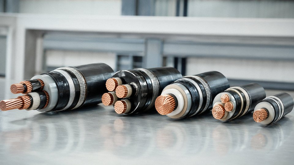
Jinda produces Type 4 equivalents to IEC 60502-1, BS 5467, and BS 6346 (the legacy SWA standard still referenced on older UK project specs and refurbishment contracts more often than people admit). For projects in Southern Africa or Australia referencing SANS 1507 or AS/NZS 1158 construction parameters, Jinda’s technical team works from the client’s project specification directly rather than forcing a catalogue product into a non-native standard. Certification coverage includes third-party type approvals from recognised international bodies, supporting the documentation packages needed for import clearance and project engineer sign-off.
Jinda holds third-party type approvals from internationally recognised certification bodies covering IEC 60502-1 and BS 5467 cable constructions.True
Jinda's manufacturing bases operate under audited quality management systems with third-party product certification, standard for cable manufacturers supplying to regulated international markets.
Customisation for Non-Standard Project Variants
Large EPC contracts rarely want a cable straight out of a catalogue. A project may need a specific conductor stranding class for a flex-to-install mining application, a particular armour configuration to satisfy a local utility’s protection coordination study, or a non-standard core colour sequence to comply with a regional wiring code. Jinda’s in-house R&D team handles those adaptations — conductor class, insulation compound selection (including compounds targeting the 90°C XLPE thermal regime for higher continuous current ratings), armour type, and colour coding — with the engineering documentation to back it up for the project record.
Quality Assurance at the Factory Level
Routine and type testing capabilities at Jinda’s facilities cover the range required under IEC 60502-1 and its equivalents: conductor resistance measurement, high-voltage routine testing, partial discharge testing on XLPE-insulated cables, mechanical property testing of insulation and sheathing compounds, and fire performance testing. That internal capability matters because it compresses the feedback loop between production and test results, catching a compound batch or stranding issue before it ships rather than after it arrives on site.
Supply Chain and Documentation for International Procurement
Jinda supplies buyers in more than 50 countries, and the commercial infrastructure around those shipments is genuinely set up for international project procurement — test certificates, material declarations, REACH and RoHS compliance documentation, and country-of-origin paperwork suited to customs requirements and tender submission packages. The technical sales team communicates in English and can work from a project specification or a bill of materials to produce a referenced quotation that maps directly to the tender document.
Procurement engineers and project managers with an active specification or upcoming bulk requirement are welcome to contact Jinda’s technical sales team for a specification review, sample request, or project quotation.