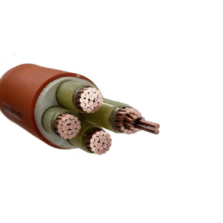
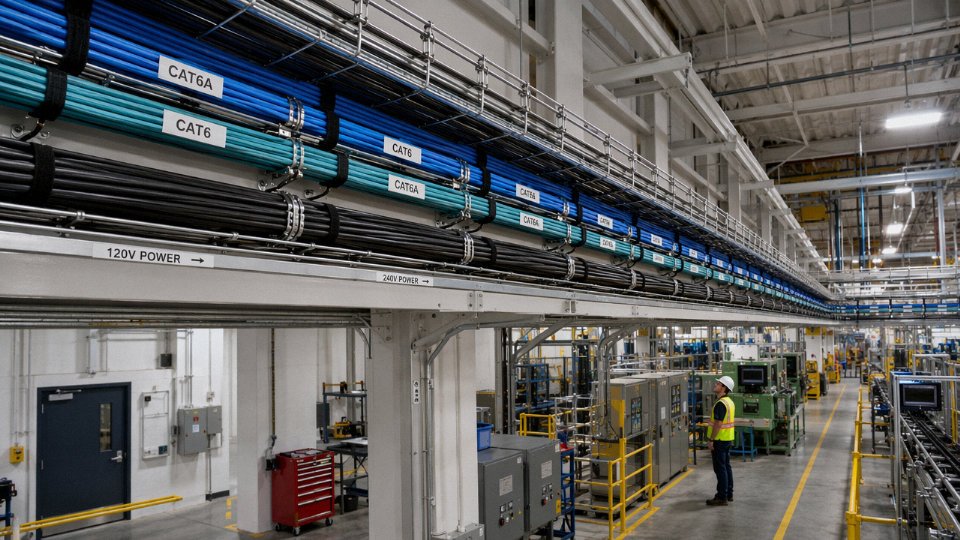
Facilities teams get this wrong more than you’d think — they bundle Ethernet runs alongside 120V or 240V branch circuits to save conduit space, then spend weeks chasing intermittent link drops, corrupted data frames, and PoE devices that brown-out under load. The induced noise and ground-loop interference quietly degrade throughput long before anything visibly fails. By the time someone traces the problem to improper cable routing, the rework cost — pulling new conduit, re-terminating drops, retesting — easily runs into several thousand dollars on a mid-sized plant floor, not counting production downtime.
Yes, Ethernet cables are low-voltage. Data signals on standard Ethernet pairs run at roughly 2.5V to 5V, and even Power over Ethernet (PoE) — the highest voltage you’ll normally encounter on an Ethernet cable — tops out at 48V DC under IEEE 802.3bt. Both NEC Article 800 and IEC 60950-1 formally classify Ethernet cabling as SELV (Safety Extra-Low Voltage) circuits, sitting below the 60V DC threshold that triggers high-voltage handling requirements.
What makes this more complicated in practice is that “low voltage” covers a surprisingly wide range of real-world conditions — a passive Cat5e patch cord and a Cat8 cable carrying 90W of PoE to a PTZ camera are technically both low-voltage, but they behave very differently in a crowded cable tray, and the installation rules that apply to each are not identical.
How Ethernet Cable Categories Define Voltage Handling and Signal Integrity
Category rating is where a lot of procurement decisions go wrong. Engineers often treat Ethernet cable as a commodity — “just get Cat6” — without recognizing that the category number encodes a specific bundle of electrical, mechanical, and insulation decisions that directly affect how cleanly the cable handles differential voltages and how much margin it holds against voltage stress from adjacent circuits.
Frequency, Segment Length, and What That Actually Means for Voltage Stress
Each category is rated to a maximum bandwidth and carries a 100-meter segment limit (with one exception worth watching). Cat5e runs to 100 MHz, Cat6 to 250 MHz, Cat6A to 500 MHz, Cat7 to 600 MHz, and Cat7A pushes to 1000 MHz. Cat8 is the outlier — rated to 2000 MHz but restricted to 30 meters, which is why it’s essentially a data-center patch and switch-to-server technology rather than a horizontal-run cable.
Higher frequency means tighter timing requirements on the differential signal, which in turn demands better dielectric consistency and tighter conductor geometry. At 2000 MHz, even a small variation in insulation wall thickness changes the characteristic impedance enough to cause reflections. This is why Cat8 cables specify 22 AWG solid conductors with controlled insulation eccentricity — the voltage levels are still low (2.5–5V differential for data signals, 48V DC for PoE), but the geometry has to be nearly perfect or signal integrity collapses.
Insulation Dielectric Strength: The Safety Margin Nobody Talks About
Standard polyethylene (PE) insulation on Cat5e and Cat6 conductors is typically rated to withstand 1000–1500V AC for one minute per IEC 61156 test protocols — sometimes reaching 2000V on premium-spec cables. FEP (fluorinated ethylene propylene), used in plenum-rated Cat6A, Cat7, and Cat8, carries comparable or slightly higher withstand ratings along with better thermal stability.
Against actual operating voltages of 2.5–5V for data and 48V DC for PoE, that’s a withstand ratio of roughly 20:1 to 400:1 depending on the conductor and the PoE load. That margin is exactly what underpins the SELV (Safety Extra-Low Voltage) and NEC Article 800 classification. The cable isn’t “safe” by accident — it’s engineered with far more insulation than the operating voltage demands, specifically because the installation environment is unpredictable.
Shielding Architectures and Induced Voltage Risk
U/UTP (unshielded) cables rely entirely on pair twist rates to cancel induced noise. That works reasonably well in clean environments, but route a bundle of Cat5e U/UTP cables within 50mm of a 240V power conduit and you’ll likely see elevated alien crosstalk and common-mode noise — not catastrophic, but enough to push error rates up or reduce effective PoE efficiency.
F/UTP adds an overall foil shield and handles moderate EMI environments well. U/FTP shields each pair individually, which is more effective at suppressing pair-to-pair crosstalk at higher frequencies. S/FTP — a braided outer shield plus individual foil-shielded pairs — is the architecture used in Cat7 and Cat8 and is what you need in industrial environments near VFDs, motors, or dense power cable trays.
Here’s the catch with shielded cable: grounding matters more than the shield itself. A shield grounded at both ends in a facility without a common equipotential bonding system will create a ground loop. That loop becomes a voltage source. Measured values are usually small — a few millivolts to maybe a volt — but at 500 MHz or above, even that corrupts the signal margin. Ground at one end only (typically the patch panel end) unless your facility has verified equipotential bonding.
| Category | Bandwidth | Segment Limit | Shielding Type | Conductor AWG | Insulation Material | Withstand Voltage (typical) |
|---|---|---|---|---|---|---|
| Cat5e | 100 MHz | 100 m | U/UTP | 24 AWG | PE | 1000–1500V AC / 1 min |
| Cat6 | 250 MHz | 100 m | U/UTP or F/UTP | 23–24 AWG | PE | 1000–1500V AC / 1 min |
| Cat6A | 500 MHz | 100 m | F/UTP or S/FTP | 23 AWG | PE or FEP | 1500–2000V AC / 1 min |
| Cat7 | 600 MHz | 100 m | S/FTP | 22–23 AWG | FEP or LSZH | 1500–2000V AC / 1 min |
| Cat7A | 1000 MHz | 100 m | S/FTP | 22 AWG | FEP | 1500–2000V AC / 1 min |
| Cat8 | 2000 MHz | 30 m | S/FTP | 22 AWG | FEP | 1500–2000V AC / 1 min |
Withstand values depend on insulation wall thickness and dielectric material; FEP-insulated cables tend toward the higher end of the range.
Higher Ethernet cable categories (Cat6A and above) always provide better performance than lower categories in any installationFalse
Category rating reflects maximum capability under ideal conditions. In short runs under 15 meters, Cat5e and Cat6 often perform identically to Cat6A for standard data traffic. Category selection should match the actual frequency, run length, and EMI environment — over-specifying adds cost without benefit in low-interference, short-run scenarios.
Consistent Insulation Thickness: Why Manufacturing Tolerance Matters for Voltage Performance
Insulation wall thickness in Ethernet cable production is not decorative — it directly determines capacitance per unit length, characteristic impedance, and the actual dielectric withstand margin. A nominal 0.20mm PE insulation wall that varies by ±0.05mm batch to batch produces impedance variation that shows up as return loss degradation, particularly above 250 MHz.
Jinda’s production lines for Cat5e through Cat8 hold insulation thickness tolerances to ±0.02mm across all five manufacturing bases, which is tighter than many commodity-market specifications. For procurement managers sourcing in volume across multiple project phases, that batch-to-batch consistency means the first shipment and the sixth shipment will test to the same withstand voltage values and the same insertion loss profile — something that matters more than most buyers realize until they’re troubleshooting a link failure in phase three of a building rollout.
Power over Ethernet Explained: When Low Voltage Means 48 Volts DC
The label “low voltage” is accurate for Ethernet cabling, but it can lull engineers into underspecifying cable for PoE deployments. At 48V DC and nearly 2A on some circuits, the physics of resistance, heat, and voltage drop start to matter in ways that pure data cabling never demands.
The Four PoE Standards and What They Actually Push Through the Cable
IEEE 802.3af (Type 1) delivers up to 15.4W at the power sourcing equipment output, with current capped around 350 mA and a PSE output voltage ranging from 44V to 57V DC. That’s workable for IP phones and basic access points. 802.3at (Type 2) doubles the budget — up to 30W, roughly 600 mA — which covers higher-end wireless APs and some PTZ cameras. So far, the thermal load on the cable is modest if the installation is done right.
802.3bt changes the conversation. Type 3 allows up to 60W at the PSE, drawing up to 960 mA, and Type 4 pushes to 90W with currents approaching 1920 mA. The PSE output voltage band for bt tightens to 50–57V. At these power levels, you are not just routing a signal cable; you are running a DC power circuit that happens to carry data alongside it.
Mode A, Mode B, and 4-Pair PoE — Why Wiring Mode Affects Your Cable Choice
PoE can deliver power in two classic configurations. Mode A uses the data pairs (pins 1,2,3,6 in a standard T568B termination) as the power conductors — the same pairs carrying the differential data signals. Mode B uses the “spare” pairs (pins 4,5,7,8). Either way, current flows out on one pair and returns on the other in that pair group, which is why the calculation that matters is the loop resistance, not the one-way resistance.
For 802.3bt Type 3 and Type 4, both pair groups carry power simultaneously — Mode A and Mode B active at the same time across all four pairs. This distributes current more evenly, which reduces per-conductor heating, but it also means that every pair in the cable is now doing real electrical work, and cable quality across all eight conductors becomes non-negotiable.
Voltage Drop: Running the Numbers on a Long Run
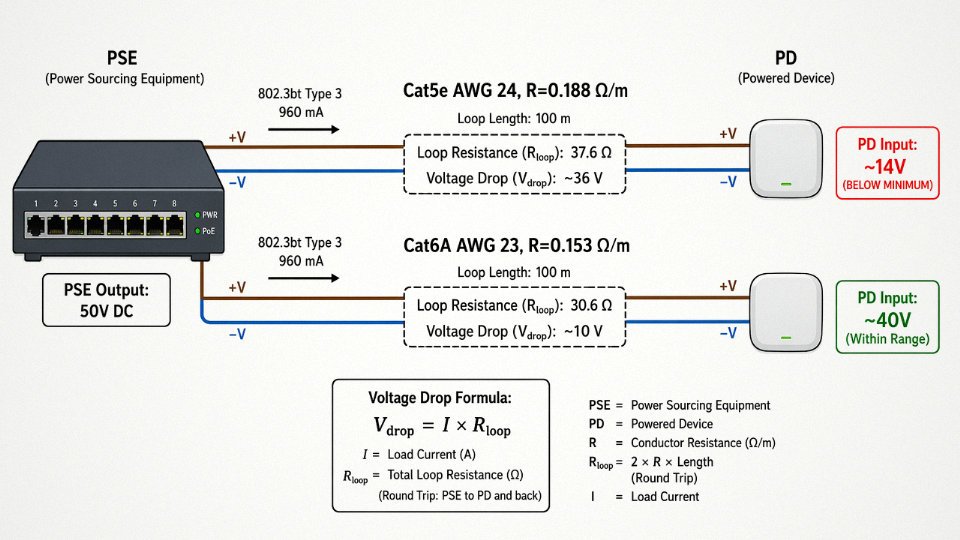
The formula is straightforward: V_drop = I × R_loop, where R_loop = 2 × cable length × resistance per meter. Cat5e solid copper typically measures around 0.188 Ω/m per conductor. On a 100m run with 802.3bt Type 3 at 960 mA — using two pairs per polarity, which halves the effective resistance — the loop resistance per pair group is roughly 2 × 100 × 0.188 = 37.6 Ω, and voltage drop across that pair group runs approximately 36V. That’s not a rounding error. A PSE outputting 50V could deliver as little as 14V to the powered device, well below the 802.3bt minimum PD input of 42.5V. The device either resets or never powers on.
Moving to Cat6A with AWG 23 conductors (roughly 0.153 Ω/m) and running all four pairs for 802.3bt closes that gap considerably. This is why Cat6A or better is the practical minimum for Type 3 and Type 4 deployments at full segment length. AWG 24 is the absolute floor for shorter runs; AWG 23 solid copper is the realistic recommendation for anything near 100m.
Bundle Heating: The Problem That Only Shows Up Six Months After Installation
A single PoE circuit generating modest heat is not a problem. Fifty of them bundled together in a cable tray absolutely is. IEC TR 29125 and TIA TSB-184-A both address this, providing derating guidance for bundled cables carrying PoE loads. The core finding: temperature rise in a bundle is cumulative, and conductor resistance increases with temperature (roughly 0.4% per °C for copper), which further increases heating — a feedback loop that can push cable jacket temperatures well above the 60°C rated limit if the tray fill and PoE density are not calculated in advance.
Solid bare copper conductors with tight dimensional control handle this better than copper-clad aluminum. CCA conductors carry 40–45% higher resistance than equivalent-gauge pure copper, meaning they run hotter at the same current, lose more voltage over the run, and are more vulnerable to corrosion at termination points — all of which compound in a PoE-heavy installation. Jinda’s Ethernet cables use solid bare copper conductors with verified geometry, which directly supports the consistent resistance figures that bundle-heating calculations depend on.
CCA (copper-clad aluminum) conductors are a safe substitute for solid bare copper in PoE cable runsFalse
CCA has approximately 40–45% higher resistivity than pure copper at equivalent AWG gauge. In PoE applications this produces greater voltage drop, higher thermal output per conductor, and faster corrosion at crimp and punch-down terminations. IEEE and TIA standards for structured cabling require solid or stranded bare copper; CCA does not meet TIA-568 compliance for PoE deployments.
What to Specify for a PoE-Ready Installation
For 802.3bt Type 3 or Type 4 deployments, the selection criteria are not complicated, but each point has a real consequence if skipped. Solid conductor, not stranded — stranded has higher resistance per AWG. Pure copper, not CCA. Cat6A minimum, verified to IEC 61156-5 or TIA-568-2.D, because the tighter pair geometry and improved crosstalk performance at 500 MHz also correlate with more consistent DC resistance across all four pairs. Independently tested voltage withstand, since the insulation between conductors needs to handle 48V DC continuously under bundle-heating conditions, not just at ambient temperature in a lab.
At 90W, Ethernet cabling is doing real electrical work. Specifying it like a signal-only cable is the kind of decision that produces a service call six months after commissioning.
Regulatory Classifications: How Codes and Standards Define Ethernet as Low Voltage
Understanding where Ethernet cabling sits in the regulatory hierarchy matters more than most installers realize — get it wrong and you’re either over-engineering the installation (wasted conduit, unnecessary separation distances, cost overrun) or under-engineering it (failed inspection, insurance liability, potential fire hazard in a plenum ceiling). The classification frameworks are actually consistent across the major standards bodies, which makes this easier to navigate once you know the structure.
IEC Voltage Band Classification: Band I Is Where Ethernet Lives
IEC 60449 and the more recent IEC 62368-1 (which replaced IEC 60950-1 for audio/video and IT equipment) both organize voltages into distinct hazard bands. Band I covers circuits up to 50V AC or 120V DC ripple-free — this is the SELV (Safety Extra-Low Voltage) territory. Band II runs from there up to 1000V AC or 1500V DC, which is where your standard mains distribution sits.
Ethernet data signals, typically in the 2.5–5V range, are deep inside Band I. PoE, even at its highest current delivery under IEEE 802.3bt (nominally 48–57V DC at the PSE port, measured up to roughly 50–57V depending on the injector), is still classified within Band I because IEC 62368-1 evaluates the accessible voltage under fault conditions, not just the nominal supply voltage. In practice, this means even a Cat6A cable running a PoE++ device to a ceiling-mounted access point stays firmly in the SELV classification. No Band II handling requirements apply.
PoE cabling at 48V DC is classified as SELV under IEC 62368-1 and does not require high-voltage installation practices.True
IEC 62368-1 classifies circuits below 60V DC as SELV (Safety Extra-Low Voltage) under Band I, and PoE operates at 48–57V DC nominal, keeping it within this band even under the 802.3bt standard's highest power tier.
NEC Article 800 and Cable Jacket Ratings
In the US, NFPA 70 (NEC) Article 800 governs communications circuits — and Ethernet cable is squarely a communications cable, not a power cable. This distinction is not just semantic. It determines which listing marks your cable needs, which conduit fill tables apply, and how the cable is treated in mixed-use pathway systems.
The NEC’s jacket rating hierarchy for communications cable runs: CMX (residential, limited use), CM (general purpose), CMR (riser-rated, flame-retardant for vertical runs), and CMP (plenum-rated, low-smoke, low-flame-spread for air-handling spaces). These ratings encode both fire-resistance performance and low-smoke/low-toxicity requirements — a CMP-rated cable has passed UL 910 (Steiner tunnel test), not just a basic vertical flame test. Specifying CMR in a plenum ceiling is a code violation, full stop. It happens on job sites more often than it should, usually because someone substituted a cheaper reel without checking the stamp.
The separation from power conductors under NEC 800.133 is a separate concern but follows from the same classification logic: communications cables must be kept away from Class 1 power circuits, though the code allows shared raceways with Class 2 and Class 3 circuits under specific conditions.
ANSI/TIA-568 and TIA-569 Separation Requirements
ANSI/TIA-568.0-D establishes the performance baseline for communications cabling and references voltage limits consistent with SELV classification. The companion standard TIA-569 (pathways and spaces) specifies the physical separation distances that protect signal integrity and safety simultaneously. The required minimums: 50 mm separation from power circuits carrying 0–2 kVA, 100 mm from 2–5 kVA circuits, and 150 mm from circuits above 5 kVA. These are minimums — in a noisy industrial environment with VFDs or large motor starters nearby, doubling those distances is not unusual and is often worth doing.
Crossed or bundled Ethernet and power runs in the same tray are one of the more reliable ways to introduce intermittent link drops that are genuinely difficult to diagnose. The cable will test fine on a Fluke DSX at installation; the crosstalk problem only shows up under full electrical load. A small separation gap prevents a large troubleshooting headache months later.
IEC 11801 and EN 50173 for International Projects
IEC 11801 (generic cabling for customer premises) and its European harmonized equivalent EN 50173 series reinforce the SELV classification and extend it into specific guidance for mixed-use buildings — commercial offices, hospitals, industrial facilities — where Ethernet infrastructure and mains power share the same cable management systems. EN 50173-1 in particular ties the cabling class (Class D through Class FA, corresponding roughly to Cat5e through Cat8) back to the electrical safety bands, confirming that all recognized horizontal and backbone cabling categories remain within SELV limits.
For export projects, this alignment between IEC and EN standards simplifies documentation considerably. Jinda’s cable production is tested and certified against both IEC and GB/T standards, which means the same product can satisfy inspection requirements across European CE-marked projects, Gulf Cooperation Council infrastructure work, and Southeast Asian public-sector tenders — markets where inspectors increasingly request third-party test reports against named international standards rather than just manufacturer datasheets. That dual-certification pathway matters when a procurement manager needs to close a project in, say, both Germany and Saudi Arabia from the same cable reel order.
Industrial Ethernet Environments: Managing Low Voltage Cables in High-EMI Settings
Factory floors are not data center floors. That distinction sounds obvious, but it gets ignored often enough that it causes real production losses — corrupted encoder feedback, tripped safety relays, nuisance faults on servo drives — all traced back to an unshielded Cat5e cable running parallel to a 400 kW VFD cabinet.
Why Low-Voltage Ethernet Is Vulnerable in Industrial Zones
The signal voltage inside an Ethernet cable is low by design: a few volts differential on twisted pairs. That’s exactly what makes it susceptible in a heavy industrial environment. Variable-frequency drives generate common-mode voltages that can reach 1,000–1,600 V peak depending on switching frequency and DC bus voltage, and they radiate that energy into anything nearby that acts as an antenna. An unshielded cable run of even 15–20 meters in the vicinity of a VFD panel will pick up enough induced noise to push bit error rates above what the PHY can correct, especially at Gigabit speeds where the noise margin is tighter than most people realize.
It isn’t just VFDs. Inductive loads — motor contactors, solenoid valves, transformer-coupled equipment — create transient spikes when they switch. Ground potential differences between separate buildings or between a motor frame and a PLC enclosure can routinely impose 5–50 V onto cable shields, and in poorly bonded facilities that number climbs further. None of these voltages are on the Ethernet cable by design. They arrive from outside, and they don’t need to be large to corrupt a real-time control signal.
Cable Construction That Actually Holds Up
For industrial Zone 1 and Zone 2 installations — as defined in IEC 61918 and the IEC 61784-5 series covering PROFINET, EtherNet/IP, and Modbus TCP fieldbus profiles — shielded cable isn’t optional; it’s explicitly required. In practice, S/FTP (individual pair foil shields plus an outer braid) or SF/UTP (foil plus braid over the whole bundle) gives you two layers of attenuation against both electric-field and magnetic-field interference. A drain wire matters too: it gives you a reliable termination path to the shield without relying on incidental contact inside the connector backshell.
Jacket material is the other variable most specs underestimate. Standard PVC gets brittle below around -10°C and degrades quickly in the presence of cutting oils, coolants, and UV exposure from skylights or outdoor sections. PUR (polyurethane) jackets rated -40°C to +90°C are the practical standard for machine tool environments; LSZH-PUR compounds are increasingly specified for enclosed production areas where smoke toxicity matters. For cable tray runs with mechanical abuse risk — steel swarf, fork truck contact, heavy conduit edges — SWA (steel wire armored) or STA (steel tape armored) variants provide crush and impact protection that no amount of careful routing fully replaces.
Equipotential Bonding: The Ground Loop Myth
A persistent misconception among electricians crossing over from building wiring is that grounding a cable shield at both ends creates a ground loop that introduces hum. In a properly bonded industrial facility — one that follows IEC 62305 and has a common equipotential bonding network — dual-end grounding is correct and necessary. It turns the shield into a return path for induced currents, dissipating the energy rather than letting it appear as a voltage differential between cable ends. Single-point grounding only makes sense in older facilities where the bonding network is inadequate, and even then it’s a workaround, not a solution.
Grounding an Ethernet cable shield at both ends always causes harmful ground loops in industrial installations.False
Dual-end shield grounding is correct practice in facilities with proper equipotential bonding per IEC 62305. It neutralizes induced voltages by providing a low-impedance return path. Ground loops only become a real problem where the facility bonding network is inadequate — a reason to fix the bonding, not to float the shield.
PROFINET and EtherNet/IP: Signal Integrity in Real-Time Control
PROFINET IRT (isochronous real-time) cycles run at 250 µs or tighter. At that cycle time, a single corrupted packet doesn’t just generate a retry — it can miss a control deadline, causing a position error on a servo axis or a false E-stop. EtherNet/IP with implicit messaging has similar sensitivity. The cable’s low-voltage signal integrity isn’t an abstract spec; it’s directly upstream of whether your motion control or process loop stays in tolerance. This is the argument that justifies shielded Cat6A over cheaper alternatives even when the budget is tight.
Jinda’s Industrial Ethernet Cable Range
Jinda produces armored Cat6A and Cat7 cables with PUR outer jackets, tested for compatibility with IP67-rated industrial connectors and designed for the -40°C to +90°C operating range typical of outdoor and heavy-process environments. Drums are available in continuous lengths up to 1,000 m, which matters on large factory campuses and outdoor utility runs where field splices introduce both signal degradation and potential ingress points. Minimizing splice count in an industrial Ethernet trunk isn’t fastidiousness — it’s directly reducing your fault probability over the cable’s service life.
Outdoor and Direct-Burial Ethernet Runs: Voltage, Moisture, and Long-Term Insulation Integrity
Running Ethernet outdoors introduces a failure mode that indoor installations rarely face: slow, progressive insulation degradation that doesn’t kill your link on day one but quietly erodes it over months or years until you’re chasing intermittent drops in the middle of winter.
How Moisture Rewrites the Voltage Picture
A properly manufactured Cat6 cable in a dry indoor run will show insulation resistance well above 500 MΩ per 100 m — that’s the IEC 61156 floor, and most quality cable tests significantly higher when new. That figure matters because it determines how cleanly the low-voltage data signals (typically 2.5 V to 5 V at the conductor pairs) stay isolated from each other and from ground. Once moisture finds a path in — through a jacket nick, a poorly sealed field termination, or a connector left exposed to condensation cycling — that resistance can collapse to the kilohm range. We’re talking a six-order-of-magnitude drop in some worst cases. At that point you’re not just losing signal quality; you’ve created unintended conduction paths between pairs that distort the differential voltage the PHY relies on. Gigabit links are particularly sensitive because the encoding scheme uses five voltage levels, not two. A degraded pair doesn’t always show as a dead link — it often presents as elevated error counts and unexplained retransmissions that are maddeningly difficult to trace back to a wet splice in a buried conduit 80 meters away.
Construction That Earns a 20–25 Year Service Life
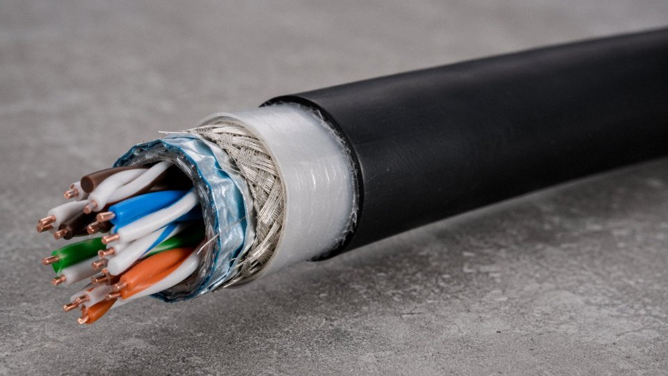
Outdoor-rated direct-burial Ethernet cable earns its price premium through layers that each serve a specific function. The flooded gel core — or in more recent designs, a helically applied water-blocking tape — surrounds the twisted pairs and stops longitudinal water migration cold. If the jacket is breached at one point, the gel limits how far moisture travels along the cable’s length. The outer jacket on a properly specified burial cable is UV-stabilized HDPE or MDPE, not the standard PVC you’d see on a patch cord. PVC gets brittle in sustained UV exposure and can crack within three to five years above ground in high-UV climates; HDPE holds up for decades.
For routes with rodent pressure or rocky soil, corrugated steel armor (or aluminum where weight matters on aerial runs) provides mechanical protection without meaningfully increasing the cable’s voltage withstand requirements — the armor just becomes part of the grounding scheme. Collectively, these layers exist to preserve the cable’s rated voltage withstand through thermal cycling, freeze-thaw, and soil movement across a service life measured in decades, not years.
Grounding the Shield at Building Entry — Non-Negotiable
Any shielded outdoor Ethernet cable needs its shield bonded to the building’s main ground bus at the point of entry. NEC Article 800.100 and IEC 60728-11 both require this, and it’s one of those steps that gets skipped on smaller jobs with expensive consequences. Ethernet cable is a low-voltage SELV system, but a 30-meter outdoor run between two buildings is an effective antenna for lightning-induced surge energy. The shield bond diverts that transient to ground before it reaches the switch port. Without it, even a nearby strike — not a direct hit — can deliver enough induced voltage to destroy PHY chips.
Surge Protection Matched to Ethernet Signal Levels
The SPD selection for outdoor Ethernet runs is tighter than most engineers expect. IEEE C62.41 classifies outdoor building entry as a Category C exposure environment — the harshest. The SPD clamping voltage needs to stay below roughly 10 V on the data pairs to avoid clipping the Ethernet signal; IEC 61643-21 covers Gigabit-compatible data line SPDs specifically. Devices rated for Fast Ethernet only can present enough series impedance to fail a Gigabit link even when the protection function itself works fine. Worth verifying on the datasheet before installation.
A standard indoor-rated PVC Ethernet cable can serve as a long-term direct-burial cable if placed inside a sealed conduit.False
Conduit sealing is rarely perfect over time, and PVC jackets are not formulated for sustained soil chemistry exposure or freeze-thaw stress. Direct-burial runs require cables specifically constructed with flooding compound or water-blocking tape and outdoor-grade jacket materials — conduit alone does not substitute for proper cable construction.
Aerial and Direct-Burial Options from Jinda
Jinda’s outdoor Ethernet range includes figure-8 self-supporting aerial cable with an integrated galvanized steel messenger wire — useful for campus spans between buildings where trenching isn’t practical. The messenger wire carries the mechanical load; the cable itself hangs stress-free. Gel-filled variants are tested to IEC 60811 for water penetration resistance, and because outdoor deployments often involve awkward run lengths that don’t match standard reel sizes, Jinda supports custom cut-to-length ordering for utility-scale and campus projects where ordering 500 extra meters “just in case” adds real cost.
In practice, the cables that fail outdoor runs early almost always trace back to one of three things: undersized jacket material selected to hit a low unit price, shield terminations done in the field without proper weatherproofing, or missing SPDs at the building entry. The cable construction and the grounding scheme work together — specifying one without the other leaves the system incomplete.
Comparing Ethernet Cable Low-Voltage Performance Against Other Low-Voltage Cabling Types
Not all low-voltage cables behave the same way on the job site, and lumping them together in a specification or routing plan is where projects get into trouble. The table below gives procurement managers and system designers a working reference — real operating voltages, applicable codes, and separation minimums for the cable types you’re most likely to encounter in the same conduit run or cable tray.
| Cable Type | Typical Operating Voltage | SELV Classified? | Governing Code | Min. Separation from Power (typical) |
|---|---|---|---|---|
| Ethernet Cat5e–Cat6A (UTP/STP) | 2.5–5V signal; up to 48V DC (PoE) | Yes (below 60V DC) | NEC Art. 800 / IEC 11801 | 50–200 mm depending on standard and shielding |
| Ethernet Cat8 | 2.5–5V signal; PoE-capable variants | Yes | NEC Art. 800 / IEC 11801 | 50–200 mm |
| Coaxial RG-6 / RG-11 (CATV/CCTV) | ~1V RF signal; 12–18V DC bias on some runs | Yes | NEC Art. 820 | 50 mm minimum from power in most jurisdictions |
| Fiber Optic (all Ethernet grades) | Zero conducted voltage on fiber | N/A — no electrical hazard on signal path | NEC Art. 770 | Minimal; EMI separation not required |
| Telephone / DSL twisted pair (POTS) | 48V DC idle; up to ~90V AC during ringing | No — ringing voltage exceeds SELV threshold | NEC Art. 800 | 50–200 mm; treat ringing voltage as elevated risk |
| Speaker cable (passive, 8 Ω loads) | Typically under 10V RMS at normal levels; 70V line systems possible | Depends on system voltage | NEC Art. 640 | 50 mm from power as general practice |
| Fire alarm cable | 24V DC typical; some systems to 120V AC | Varies by circuit type | NEC Art. 760 / NFPA 72 | Dedicated pathways usually required; check AHJ |
One thing jumps out: POTS telephone lines technically carry higher peak voltage than standard PoE during a ringing cycle — roughly 90V AC — which puts them outside the SELV boundary that Ethernet comfortably sits within. That surprises people. In practice, old telephone infrastructure and Ethernet often share the same cable trays in retrofitted commercial buildings, and that combination deserves more attention than it usually gets.
Why Ethernet Needs Tighter Routing Discipline Than Its Voltage Suggests
The separation minimums in that table aren’t just about shock hazard. A 48V PoE circuit is not going to electrocute anyone under normal conditions. The real discipline around Ethernet routing comes from signal integrity, and that’s a different problem entirely.
Cat6A running 500 MHz differential signals is extraordinarily sensitive to induced noise. A parallel run next to a switched-mode power supply feed or a VFD cable — even at the legally compliant 50 mm separation — can inject enough common-mode noise to drop link speeds or cause intermittent packet loss. Speaker cable at 20 Hz to 20 kHz? That same interference barely registers. Fire alarm loops running at DC or low-frequency polling? Mostly immune. Ethernet is the most electrically fragile cable in that table despite not being the most hazardous, which is a distinction worth making explicit to any facilities team doing mixed-use cable tray planning.
The “Low Voltage Means Careless Installation Is Fine” Misconception
This one comes up more than it should. Ethernet cable voltages under data-only conditions pose essentially no electrocution risk. But a PoE-energized cable with a damaged jacket and exposed conductors at 48V DC can deliver a noticeable shock, and more practically, it can damage powered devices if bare conductors contact equipment chassis or adjacent signal lines. The voltage is not the only issue — strain relief at patch panels, proper RJ45 termination, and protected junction points matter because mechanical failure creates both performance and equipment-damage scenarios that low-voltage classification doesn’t protect against.
Fiber Optic Ethernet: The Voltage Argument for Inter-Building Runs
Fiber carries no conducted voltage on the signal path at all. That single fact eliminates EMI susceptibility, ground-loop potential between buildings with different earth references, and any voltage-related separation requirement. For runs beyond 100 m, inter-building connections, or routing through areas with heavy motor loads or high-voltage switchgear, fiber is the clean answer regardless of shielding specification.
Copper Ethernet — shielded or unshielded — remains the cost-effective default for most in-building horizontal runs under 90 m, particularly where PoE is needed, since fiber doesn’t carry power.
Decision Flow: UTP, STP, or Fiber?
Run length > 100m?
  YES → Fiber optic (single-mode for >300m, multimode for shorter)
  NO  → PoE required?
          YES → Copper required; EMI environment severe?
                  YES → STP Cat6A or Cat7 (verify shield continuity and grounding)
                  NO  → UTP Cat6 or Cat6A sufficient for most applications
          NO  → EMI environment severe OR inter-building with ground potential difference?
                  YES → Fiber preferred; STP copper acceptable if runs are short
                  NO  → UTP Cat5e/Cat6 cost-effective; Cat6A if future bandwidth matters
Jinda’s product range covers all three branches of that decision — UTP and STP copper from Cat5e through Cat8, plus fiber optic assemblies suited for industrial and commercial infrastructure — which means a project can standardize supply without splitting cable procurement across multiple vendors.
POTS telephone ringing voltage can exceed the SELV threshold of 60V DC / 42.4V AC peak, making active telephone lines technically outside the SELV classification that governs standard Ethernet cabling.True
Standard POTS ringing signals are typically 90V AC at 20 Hz, which exceeds the IEC 61140 and IEC 60950-1 SELV upper boundary. Ethernet under IEEE 802.3 PoE standards operates at 48V DC, remaining within SELV limits.
Installation Best Practices That Preserve Low-Voltage Safety and Performance Ratings
A cable that leaves the factory certified to Cat6A or Cat7 can be degraded to something considerably worse before the first packet ever travels through it. Installation mechanics — bend radius, pulling tension, separation distances, termination quality — determine whether the cable’s rated electrical performance actually survives to the patch panel. For PoE deployments especially, these aren’t abstract concerns: a stretched conductor or a crushed shielded run translates directly into voltage drop and heat, not just a marginal dip in test scores.
Bend Radius: Geometry Matters More Than It Looks
The minimum bend radius for unshielded twisted pair is 4× the cable’s outer diameter during installation, rising to 8× for shielded (S/FTP, F/UTP) and armored constructions. Violating these limits deforms the twisted pair geometry — the pairs don’t spring back to their original lay length after a tight bend. That geometric distortion increases crosstalk and alters conductor spacing in a way that shifts the cable’s distributed capacitance, which in turn affects how cleanly high-frequency voltage signals propagate. At Cat6A frequencies (500 MHz), even subtle changes in inter-pair geometry are measurable. Post-installation, the static bend radius limit is generally more relaxed (around 8× for UTP, 6× for shielded), but the damage from installation handling is permanent. In practice, the corners where cables transition from cable tray to conduit drop are the most common violation points — installers rush, and a 25 mm Cat6A cable bent around a 60 mm radius at a 90° conduit entry won’t fail a visual inspection but may fail PS-NEXT.
Pulling Tension: The Hidden Conductor Damage
TIA-569 sets maximum pulling tension at 25 lbf (roughly 110 N) for Cat6A. Exceed that and you’re permanently stretching the copper conductors. Stretched conductors have higher DC resistance, which matters directly for PoE: under IEEE 802.3bt’s 90 W budget, even a few hundred milliohms of unexpected loop resistance can push voltage at the powered device below its minimum operating threshold. Beyond resistance, overstretched insulation can develop micro-cracks that degrade the cable’s voltage withstand rating over time — not immediately obvious, but a failure mode that shows up two or three years into service in a humid environment. Use a calibrated pulling grip and a tension gauge on any run exceeding roughly 30–40 meters. Fish tape without tension monitoring is asking for trouble on long industrial pulls.
Separation from Power Conductors
TIA-569-D requires a minimum 50 mm separation between Ethernet cables and power circuits up to 2 kVA, increasing to 100 mm for 2–5 kVA and 150 mm for circuits above 5 kVA.True
These separation distances are specified in TIA-569-D Table 9-1 and exist to prevent inductive and capacitive coupling from power conductors inducing noise voltages onto Ethernet signal pairs, which degrades common-mode rejection and effective signal voltage margins.
Where Ethernet and power cabling genuinely cannot be separated — shared cable trays are common in retrofits — use a grounded metallic divider or run the Ethernet in metallic conduit. The conduit provides both the required separation barrier and meaningful EMI shielding that helps preserve the cable’s effective signal voltage margin. Plastic conduit alone satisfies the physical separation requirement but contributes nothing to shielding.
Termination Quality
Improper termination causes more field test failures than any other single factor. The limit is 13 mm (0.5 inch) of untwisted pair at termination points — exceed that and near-end crosstalk (NEXT) degrades noticeably, and slight voltage imbalances between conductors reduce the common-mode rejection that keeps data signals clean. Use the manufacturer’s dedicated punch-down or connector tool; a generic tool that doesn’t seat the IDC contacts fully creates intermittent resistance that is genuinely difficult to diagnose later. Terminate to T568B unless project specifications explicitly require T568A — mixing standards across a run is the kind of wiring mistake that passes a basic continuity check but fails channel certification.
Post-Installation Verification
Certify every permanent link with a Category-rated field tester. The Fluke DSX-8000 is the industry standard reference; equivalent-class instruments from Ideal or TREND Networks are acceptable provided they’re calibrated within the manufacturer’s recommended interval. The parameters that specifically validate low-voltage electrical performance are insertion loss (confirming conductor resistance is within spec, which is the foundation for any PoE voltage drop calculation), return loss, and PS-NEXT. A pass on all three means the cable installation will actually deliver the voltage performance its category rating promises — not just today, but across a reasonable service life.
Frequently Asked Questions About Ethernet Cable Voltage
Is it safe to touch a live Ethernet cable?
Under normal conditions, yes. Standard Ethernet data signals run below 5V DC — well within the range where healthy, dry skin presents enough resistance that you’d feel nothing at all. Even PoE at 48V DC is not considered lethal under typical contact conditions; the threshold at which DC voltage becomes dangerous to most adults starts well above that, and real-world shock risk depends heavily on skin moisture, contact area, and current path through the body.
That said, don’t get casual about it. A physically damaged cable with exposed conductors should always be de-energized before you touch it — not because the data signal will hurt you, but because a faulty PSE or non-standard PoE injector can behave unpredictably, and 48V DC will absolutely damage sensitive electronics or CMOS inputs if it finds an unintended path. In practice, the bigger hazard is hardware damage, not personal injury.
Can Ethernet cables carry enough voltage to cause a fire?
A properly installed, listed cable will not ignite from its own operating voltage. The fire risk in Ethernet installations is almost always thermal, not strictly electrical, and it comes from two specific scenarios that are worth understanding clearly.
First, dense PoE bundles. TIA TSB-184-A provides derating guidelines because tightly bundled PoE cables accumulate heat from the combined resistive losses across all pairs carrying current simultaneously. A single Cat6 cable running 802.3bt (up to 90W) in open air is fine; 24 of them in a tight conduit without derating calculations is a different situation entirely.
CCA (copper-clad aluminum) conductors present measurably higher fire risk in PoE applications than solid bare copper conductors.True
CCA conductors have higher resistivity than solid copper, generating more heat at equivalent current loads. This is a recognized issue in industry guidance, and several test reports have documented elevated temperatures in CCA cables under sustained PoE loads compared to solid copper equivalents.
Second: CCA cable. Copper-clad aluminum has higher resistance per unit length, generates more heat at the same current, and its aluminum core expands and contracts at a different rate than copper during thermal cycling — which gradually loosens terminations. Always specify solid bare copper for any PoE run, full stop.
Does the cable category affect how much voltage it handles?
Not in the way most people assume. Every category from Cat5e through Cat8 must pass a 1,000V AC insulation withstand test per IEC 61156 (Cat8 goes to 2,000V AC), so the withstand margin is effectively the same across the range when it comes to PoE operating voltages. The category rating governs frequency performance — bandwidth, insertion loss, NEXT — not voltage class.
Where category does make an indirect difference: Cat6A and Cat7 cables typically feature thicker individual conductor insulation and more controlled pair geometry, which gives you a bit more mechanical robustness against insulation damage during installation. That’s not a voltage rating improvement, but on a rough cable pull it matters.
Can I run Ethernet cable in the same conduit as 120V or 240V power wiring?
In most jurisdictions, no — not without specific engineering approval. NEC Article 800.133 and IEC 11801 both require physical separation between communications cables and power conductors above 50V AC. The separation requirement in practice ranges from 50 mm to 200 mm depending on whether shielded cable or metallic barriers are used.
Two separate problems drive this rule. The safety concern is induced voltage: a power conductor running parallel to an Ethernet cable can capacitively or inductively couple voltage onto the Ethernet pairs. The signal integrity concern is that 50 Hz or 60 Hz noise from power wiring, especially variable-frequency drives, corrupts Ethernet signals badly even when the induced voltage is technically within a safe range. Use separate conduits or a properly partitioned metal cable tray with a grounded steel divider between compartments.
What is the maximum voltage an Ethernet cable can withstand before insulation failure?
The IEC 61156 withstand test figures — 1,000V AC for one minute for Cat5e through Cat6A, 2,000V AC for Cat8 — represent roughly 200 to 400 times the actual PoE operating voltage. That’s a large safety margin by any measure.
Bear in mind these are type-test voltages, not continuous operating ratings. Sustained overvoltage above 60V DC should be handled with surge protection devices at both ends of any run exposed to lightning or switching transients. The insulation won’t fail instantly above 60V, but prolonged exposure degrades it faster than the rated service life assumes.
Are outdoor Ethernet cables still classified as low voltage?
Yes, without exception. An armored direct-burial Cat6A cable carries exactly the same data signals and PoE voltages as an indoor plenum cable and falls within the same SELV classification. The armor layer, gel flooding compound, UV-stabilized jacket, and any messenger wire are there to address mechanical and environmental durability — none of that changes what’s happening electrically inside the pairs.
How does Jinda ensure consistent voltage withstand performance across large cable orders?
Across all five of Jinda’s manufacturing bases, 100% conductor insulation resistance testing is performed on every production run, with periodic high-voltage withstand testing conducted to IEC 61156 and GB/T 5023 requirements. Third-party audits by internationally recognized certification bodies provide an independent check on in-house test data, so voltage performance figures on a data sheet reflect what actually arrives on a project site — which matters more than most procurement managers realize when a project spans multiple container shipments over 18 months.
Sourcing Ethernet Cables for Large Projects: What Voltage Specs to Verify Before Purchase
Buying Ethernet cable in bulk is not complicated — until something goes wrong six months into a deployment. A PoE lighting system running warm. Patch panels failing certification tests. An insurance inspector asking for third-party test documentation you don’t have. Getting the specification checkpoints right before purchase is far cheaper than sorting it out after.
The Five Electrical Parameters Worth Demanding in Writing
Most supplier datasheets are marketing documents dressed up as engineering documents. Before committing to a volume order, request the actual test report and check these five figures specifically.
DC resistance per conductor at 20°C. For Cat6A 23 AWG, TIA-568-2.D sets the maximum at 9.38 Ω per 100 m. This number matters most in PoE runs — higher resistance means more voltage drop and more heat generated in the conductor under sustained current. If a supplier is selling copper-clad aluminum (CCA) and not disclosing it, this is where it shows up. CCA typically runs 30–40% higher resistance than solid oxygen-free copper at equivalent gauge, which pushes you outside spec on longer PoE runs and can cause thermal issues in bundled conduit.
CCA conductors typically exhibit 30–40% higher DC resistance than solid OFC conductors at the same AWG, which can push Cat6A PoE runs outside TIA-568-2.D limits on segments approaching 100 m.True
Aluminum has roughly 1.6× the resistivity of copper. CCA conductors with a thin copper cladding over an aluminum core will have effective resistivity significantly higher than solid copper, resulting in elevated DC resistance that affects both voltage drop and heating under PoE current loads.
Insulation resistance. Minimum 500 MΩ per 100 m. Low insulation resistance is how moisture ingress and poor-quality PVC compounds announce themselves — often years after installation, when you’re chasing intermittent link drops in a ceiling plenum. Worth checking on outdoor and direct-burial cable specs especially.
Dielectric withstand voltage. Minimum 1,000 V AC for one minute between conductor and shield (or between pairs). This validates the insulation thickness and material quality. A cable that passes data signals at 2.5–5 V is still expected to hold that insulation margin as a safety buffer — it’s part of how SELV classification is maintained.
Characteristic impedance. 100 Ω ±15% for all balanced Ethernet categories. Deviation here causes reflections, and reflections cause retransmissions, and retransmissions in a 10 GbE backbone are a slow-burning operational cost that nobody traces back to the cable until a consultant runs a TDR sweep.
Pair-to-pair capacitive unbalance. This one gets skipped surprisingly often. In electrically noisy environments — near variable-frequency drives, near bus ducts, in any industrial installation — high capacitive unbalance between pairs lets common-mode noise convert into differential signal noise. It degrades alien crosstalk performance and can cause intermittent errors that are genuinely difficult to diagnose.
Self-Declared Specs vs. Accredited Test Reports
There is a practical difference between a manufacturer’s datasheet and a test report from a lab accredited under ISO/IEC 17025. Request the latter. ETL Listed, UL Listed, or a CE Declaration of Conformity backed by a named accredited lab gives you something defensible if a project audit or insurance claim requires documentation. Self-declared specs do not. This is especially relevant for PoE-capable cables where conductor purity directly affects resistance under load — the heating behavior of a CCA cable running 802.3bt (up to 90 W) in a 40-cable bundle is not the same as solid OFC, regardless of what the datasheet says.
Order Quantities, Packaging, and Lead Times
Jinda supplies standard reels of 305 m (1,000 ft) and 500 m, with bulk drum orders available up to 2,000 m for large campus or industrial projects. Export packaging meets ISPM-15 phytosanitary requirements, which matters for wood packaging crossing most international borders — it’s a detail that delays shipments when overlooked. Lead times for standard Cat6A and Cat7 run roughly 15–25 days from order confirmation, depending on specification and current production scheduling across five manufacturing bases. QC hold points are documented within an ISO 9001-compliant production system, so inspection records are available if your project requires them.

Project Services That Actually Reduce EPC Headaches
For EPC contractors managing multiple procurement packages, consistency in cable documentation is a real operational problem. Jinda supports pre-shipment inspection coordination with third-party inspectors, custom jacket printing for meter marking and project-specific cable IDs, and custom cut lengths where reel-standard sizes don’t suit the installation. Technical support for specification development is available — useful when you’re reconciling a client’s legacy spec with a current TIA or IEC standard and need someone who has worked through that before.
If your project involves Cat6A for commercial structured cabling, PoE-optimized Cat7 for smart building automation, armored industrial Ethernet for factory floors, or outdoor direct-burial cable for campus backbone runs, Jinda’s international sales team can provide technical datasheets, samples for pre-qualification testing, and volume pricing backed by 35-plus years of cable manufacturing and supply to clients across more than 50 countries. Reach out before the specification is locked — it is much easier to validate a cable against your project requirements before purchase than to run certification tests on an installed system that fails.