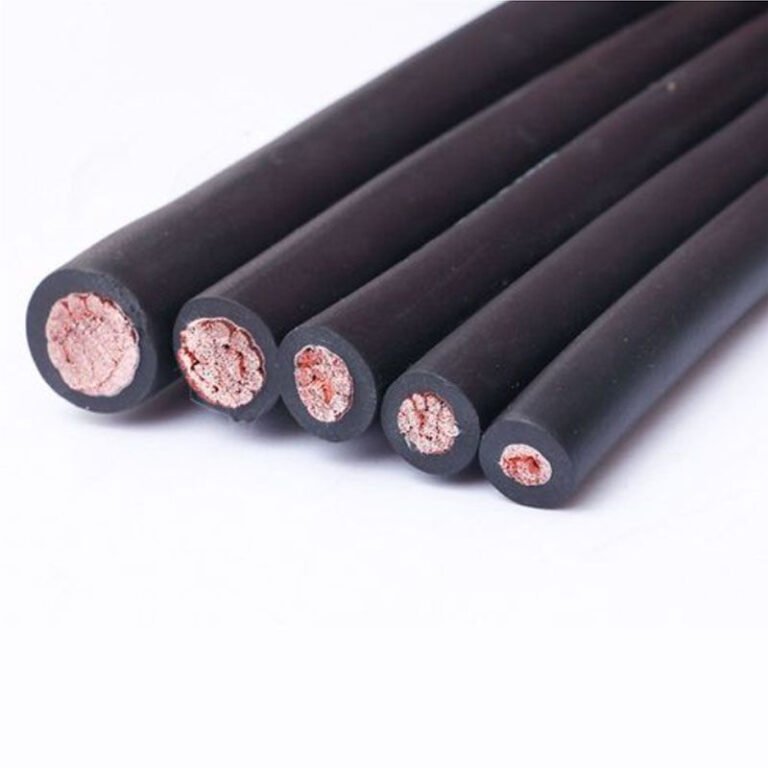
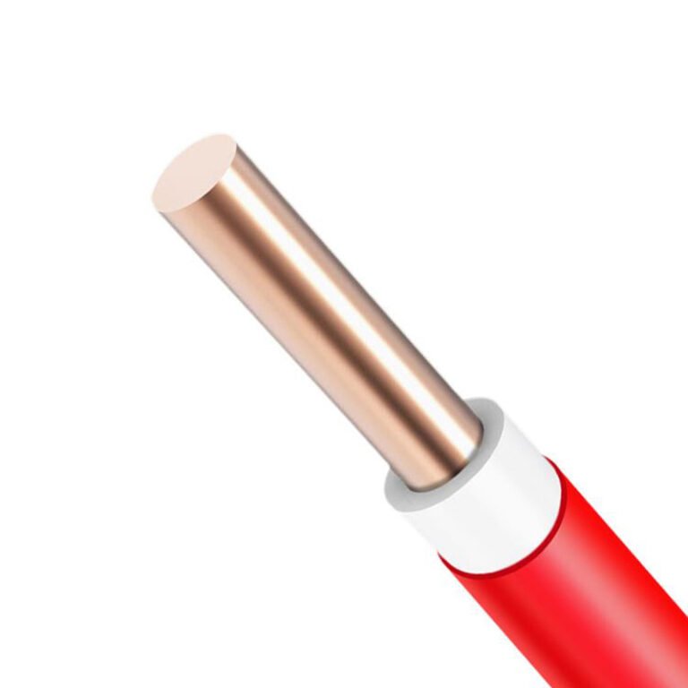
Swap a control cable for a power cable on a motor circuit — or wire up a PLC cabinet with something pulled from the power cable reel because it looked close enough — and the consequences range from nuisance faults that eat a maintenance shift to insulation breakdown, tripped protection, or a smoldering panel that writes off a production run. The cables look similar in a conduit tray. The labels are often gone by the time a cable reaches the site. Procurement teams under cost pressure sometimes substitute “equivalent” products that are anything but. Getting this wrong is cheap to do and expensive to fix.
A power cable carries electrical energy from source to load — motors, transformers, distribution boards — at voltages typically from 0.6/1 kV up to 500 kV and conductor sizes from 1.5 mm² to 2500 mm². A control cable carries low-energy signals and switching commands, rated at 300/500 V or 450/750 V, with conductors usually between 0.5 mm² and 10 mm². The difference is not just voltage class: construction, shielding, flexibility, insulation chemistry, and governing standards (IEC 60502 for power; IEC 60227/60245 for control) are fundamentally different.
What makes this genuinely tricky in practice is that the distinctions go deeper than a voltage stamp on the jacket. A cable that passes every electrical test for its rated class can still fail the application — wrong flexibility spec for a moving cable carrier, inadequate shield coverage in a noisy drive environment, conductor stranding that work-hardens and cracks in a panel that vibrates. The sections below pull those differences apart one by one.
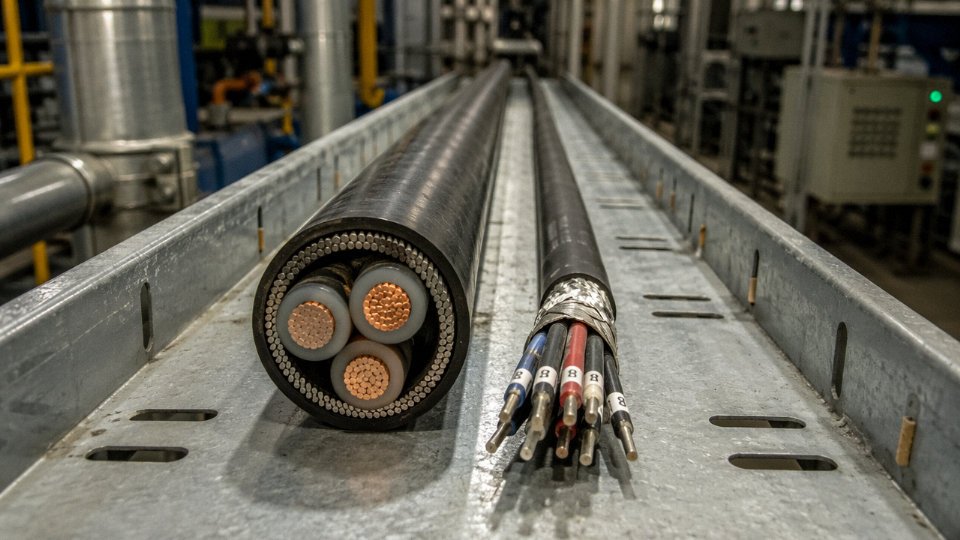
Defining Each Cable by Its Electrical Mission: Voltage, Current, and Signal Roles
A power cable exists for one reason: to move electrical energy from a source to a load at whatever voltage and current that load demands. In industrial and utility applications, that working voltage starts at 0.6/1 kV for most low-voltage distribution — factory motors, panel boards, lighting circuits — and climbs through medium voltage (roughly 6 kV to 35 kV for distribution feeders and large drive systems) up into high voltage territory at 66 kV and above for transmission and substation work. Conductor sizing in a power cable is driven primarily by ampacity — the continuous current the cable can carry without exceeding its insulation’s thermal limit — and by fault current capacity, meaning the conductor must survive the mechanical and thermal stress of a short-circuit event for the duration it takes protection to clear the fault. A 630 mm² aluminum conductor in a 33 kV underground feeder and a 2.5 mm² copper conductor feeding a 230 V convenience outlet are both power cables. The physics is the same; the scale is not.
Control cables operate in a completely different electrical regime. Their job is not to deliver energy — it is to carry commands, switching signals, and interlocking logic between devices: relay panels, PLCs, motor control centers, solenoid valves, annunciator systems, and similar equipment. Working voltages typically fall at 300/500 V or 450/750 V AC, and the actual current flowing through most control circuits rarely exceeds a few amperes, often far less. A contactor coil circuit, a start/stop pushbutton loop, an emergency stop interlock — these are the loads a control cable serves. The conductor cross-sections reflect this: typically 0.5 mm² to 6 mm², sometimes up to 10 mm² for heavier control duty, but never sized for kilowatts of load.
The cleanest way to hold the functional boundary in your head: power cables move energy that does work. Control cables move information that decides when and how that work happens.
Instrumentation Cable: The Low-Signal Sub-Category
Within the control cable family sits instrumentation cable, and it deserves separate recognition because its electrical environment is genuinely different again. Instrumentation cables carry analog signals — thermocouple outputs, 4–20 mA transmitter loops, RTD circuits, pressure transducer signals — where the working levels can be in the millivolt or low-milliamp range. At those signal levels, electromagnetic interference from nearby power cables, variable frequency drives, or bus bars becomes a real engineering problem, not a theoretical one. This is why instrumentation cables are almost always individually shielded per pair or triad, and often have an overall shield on top of that. Running an unshielded control cable into a thermocouple input on a DCS and then wondering why the trend display is noisy — that’s a diagnostic call that wastes a maintenance shift. The shield drain wire needs a proper single-point ground; floating it or grounding at both ends usually makes interference worse, not better.
Control cables rated 450/750 V can be safely substituted for power cables in low-voltage circuits because their voltage ratings overlap.False
Voltage rating is only one parameter. Power cables are designed for sustained high-current ampacity, fault current withstand, and armoring or insulation wall thickness suited to energy-carrying duty. A control cable used as a power cable will overheat under load current it was never sized to handle, and its insulation may not meet the required short-circuit withstand rating.
Why Cable Identity Is a Safety Discipline on the Plant Floor
In most industrial facilities, power cables and control cables share the same cable trays, often running in parallel for long distances. That’s normal and unavoidable given plant layout. What it means in practice is that correct identification — through color coding, sequential meter marking, cable tags at terminations, and route documentation — stops being a housekeeping preference and becomes a safety-critical discipline. Energizing the wrong cable during a modification, or terminating a 1 kV power conductor into a PLC input card because someone misread an unmarked cable, are the kinds of mistakes that generate arc flash incidents and scrapped control hardware. Most plants have had at least one near-miss along these lines. Usually it traces back to a cable that was installed without proper tagging, or where the tags were removed and never replaced during a previous turnaround.
Construction Anatomy: How Insulation, Shielding, and Armoring Differ Between the Two Types
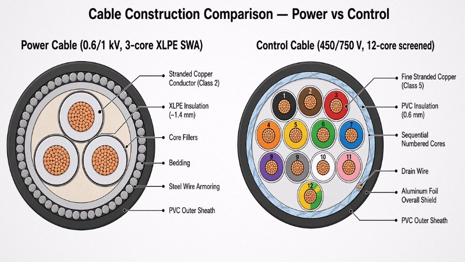
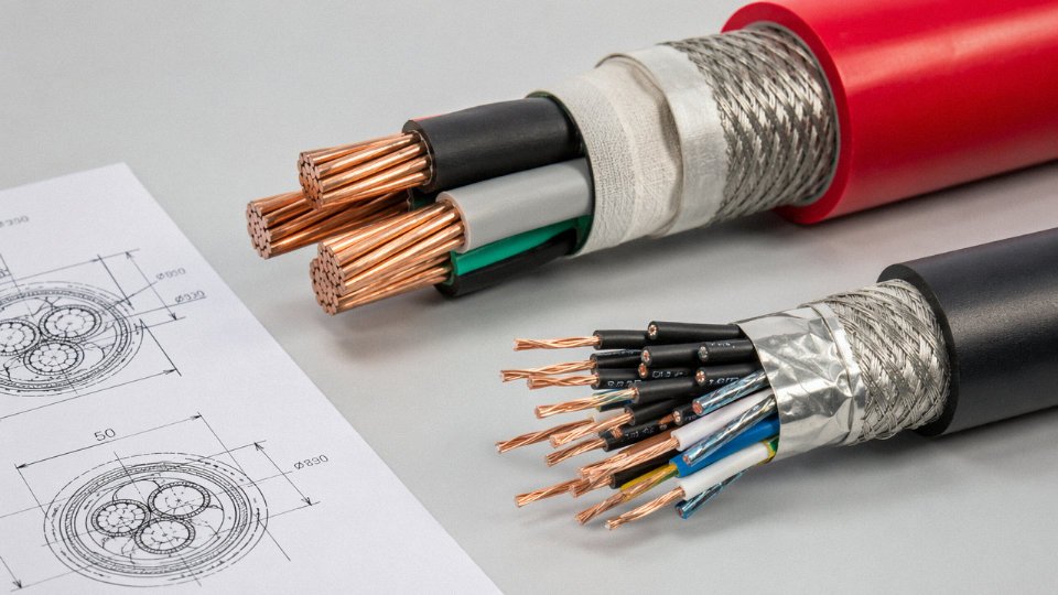
Pull a cross-section of each cable type side by side and the differences are immediate — even to someone who has never read a datasheet. Understanding what you’re looking at layer by layer is the fastest way to verify that a delivered drum is actually what the purchase order specified.
Conductor: Size and Strand Architecture
Power cable conductors are large-section stranded copper or aluminum, typically 6 mm² up to 2500 mm² in transmission-grade products, and the stranding geometry is optimized for one thing: pushing current with minimal I²R loss. The individual strands are relatively coarse — Class 2 or Class 1 construction under IEC 60228 — because flexibility is secondary to conductivity and current density. Aluminum conductors appear frequently above 95 mm² where weight and cost matter more than bending radius.
Control cable conductors are a different animal. Fine stranded copper (Class 5 or finer) in the 0.5 mm² to 10 mm² range, engineered specifically to terminate reliably in 2.5 mm or 4 mm pitch terminal blocks without fraying. A 0.75 mm² control core carrying a 24 V DC signal to a solenoid valve sees maybe 0.1 A — current capacity is almost irrelevant. What matters is that the end doesn’t fan out when a technician strips it at 2 AM during a maintenance window.
Insulation Thickness and Dielectric Specification
This is where voltage rating drives the biggest visible difference. A 10 kV XLPE power cable will have insulation roughly 3.4 mm thick on each core — sometimes thicker depending on the manufacturer’s design margin and whether it’s single-core or multicore. That thickness is calculated from the electric field gradient, not from mechanical considerations.
Control cable insulation at 450/750 V rating is typically only 0.6–0.8 mm thick. There’s no need for anything more. Applying power cable insulation thicknesses to a 24-core control cable would make it absurdly large and expensive, and the dielectric performance would be massively over-engineered.
Core Identification
Power cables — usually 2, 3, or 4 cores — use bold, easily readable color coding: brown, black, and grey for phases; blue for neutral; green-yellow for earth. You can identify a core at a glance from a meter away.
Control cables with 4, 7, 12, 19, 27, or 48 cores cannot practically rely on color alone. Sequential core numbering, printed or embossed on the insulation, is standard. Some manufacturers combine a base color with a number spiral. Either way, a site inspector receiving a 27-core screened cable should expect to see legible sequential numbers — if they’re absent or illegible, that’s a quality flag worth raising before installation.
Shielding
Individual foil or braid shields, or an overall shield, appear routinely on control and instrumentation cables because low-level signals are vulnerable to capacitive and inductive noise from adjacent power runs. An unshielded analog 4–20 mA loop routed near a VFD output cable will almost certainly pick up interference that looks like process noise.
Power cables are rarely shielded in standard industrial installationsTrue
Shielding on power cables is reserved for specific EMC-sensitive applications or certain medium-voltage cable designs; it is not a standard construction feature for typical power distribution cables.
Power cables are shielded only in special cases — certain MV designs with a metallic screen for fault current return, or EMC-critical environments. If a supplier is quoting you a shielded power cable for a standard distribution application, ask why.
Armoring
Both types can be armored — steel wire armored (SWA) or aluminum wire armored (AWA). The wire gauge on a power cable armor is noticeably heavier, though, because it has to handle the mechanical tension from the cable’s own weight in vertical risers, plus potential impact loads. A 240 mm² three-core SWA power cable might use 3.15 mm armor wires; a 12-core control cable in the same conduit might use wires closer to 0.8–1.0 mm. Jinda produces both PVC- and LSZH-sheathed variants across both categories — the sheath choice matters for tunnel or offshore installations where smoke toxicity is a concern.
Filled Cores and Moisture Blocking
Instrumentation-grade control cables, especially in outdoor or buried runs, often include a flooding compound or moisture-blocking tape between cores. Water migration along a conductor is slow but relentless — it can travel meters from an outdoor junction box into a control panel over a wet season, corroding terminal connections that are nearly impossible to diagnose remotely. Standard power cables rarely need this treatment because their insulation walls are thick enough and the terminations are more tolerant of minor contamination. If you’re specifying control cables for a coastal plant or a buried instrumentation loop, ask explicitly whether the construction includes moisture blocking. It usually adds a modest cost premium but prevents failure modes that are disproportionately expensive to trace and repair.
Electrical Parameters Side by Side: Voltage Rating, Current Capacity, and Impedance Requirements
The fastest way to confirm you have the right cable on the reel — before it gets pulled through conduit — is to check three numbers: voltage rating, conductor cross-section, and the loop resistance or capacitance specification. Everything else is downstream of those.
Voltage Rating: What U0/U Actually Means in Practice
The notation U0/U is not just bureaucratic formatting. U0 is the rated voltage between any one conductor and earth (or the metallic screen); U is the rated voltage between any two phase conductors. A cable marked 0.6/1 kV can therefore sit on a 1,000 V phase-to-phase system and still maintain its insulation integrity to earth — useful information when you are verifying whether an existing installation was correctly specified.
| Cable Type | U0/U Rating | Typical Application Context |
|---|---|---|
| Low-voltage power | 0.6/1 kV | Motor feeds, distribution boards, PV strings |
| Medium-voltage power | 3.6/6 kV | Industrial substations, wind farm collector rings |
| Medium-voltage power | 6/10 kV | Urban distribution, large process plant HV rings |
| Medium-voltage power | 8.7/15 kV | Transmission-adjacent feeders, mining |
| Medium-voltage power | 12/20 kV | European distribution standard |
| Medium-voltage power | 18/30 kV | High-voltage industrial, covered by IEC 60502-2 |
| Control cable | 300/500 V | Panel wiring, relay circuits, interlocks |
| Control cable | 450/750 V | Harsher industrial environments, some motor control |
The practical installation consequence: running a 450/750 V control cable in a tray alongside a 6/10 kV screened power cable is electrically permissible in many jurisdictions — but only if the control cable’s insulation is rated for the induced voltage stress under fault conditions. Always check the separation rules in IEC 60364-5-52 and your local network operator’s specification before assuming tray-sharing is fine.
Current-Carrying Capacity: A Very Different Design Constraint
A 95 mm² copper XLPE power cable in free air at 30°C ambient carries somewhere in the range of 270–310 A depending on installation method, grouping factor, and soil thermal resistivity if it’s buried. That range matters — a poorly ventilated cable tray in a tropical plant can knock 15–20% off the usable ampacity.
A 1.5 mm² control cable core, by contrast, might feed a relay coil drawing 0.08 A or a 24 V DC indicator lamp pulling 0.5 A. Thermal sizing is essentially never the binding constraint. The 1.5 mm² minimum is there for mechanical robustness during termination and to manage loop resistance — not because anyone is worried about overheating.
Loop Resistance and Signal Integrity
This is where control cable design diverges sharply from power cable design. Standards like BS 5839-1 (fire detection) and IEC 60364 impose maximum loop resistance limits on circuit wiring — not to prevent thermal damage, but to guarantee that a relay or detector at the far end of a long run still receives enough voltage to operate reliably. A fire alarm sounder circuit with 40 Ω loop resistance and a panel output of 24 V might not reliably activate a device with a 22 V minimum operating threshold. That’s a life-safety failure, not just an efficiency problem.
In practice, this means specifying a larger conductor cross-section on a 200 m control run — perhaps 2.5 mm² instead of 1.5 mm² — to hit a loop resistance target, even though the current load is trivial. Engineers sometimes miss this and then wonder why relays are intermittently failing to pick up at the remote end of a long cable tray run.
Capacitance per Unit Length: The Invisible Problem on Long Runs
Unshielded multi-core control cables typically exhibit mutual capacitance between cores in the range of 100–200 pF/m, depending on core count, pitch, and insulation wall thickness. On a 300 m run, two adjacent cores can share 30–60 nF of coupling capacitance. In analog 4–20 mA loops that’s usually tolerable. In digital pulse circuits or protection relay wiring, it starts causing ghost signals and spurious trips.
Capacitance balance between cores in a multi-core control cable affects signal integrity in protection relay circuitsTrue
Unbalanced capacitance causes differential signal errors and can induce spurious operation in sensitive relay inputs, particularly at 50/60 Hz where coupled voltage rises with cable length. Characterized instrumentation cables specify capacitance balance, typically ≤ 100 pF/m core-to-core, to address this.
Shielded instrumentation cables solve most of this, but shielding has to be used correctly — grounded at one end only for analog circuits, or both ends for some digital systems depending on the protocol. Getting that wrong introduces ground loops, which can be worse than no shielding at all.
Short-Circuit Withstand: Who Needs to Worry About It
The adiabatic equation k²S² ≥ I²t governs minimum conductor size for fault withstand on power cables. For a copper XLPE conductor with k ≈ 143, a prospective fault current of 25 kA for 1 second demands a minimum cross-section of roughly 175 mm². That’s a real design driver — get it wrong and the conductor fails catastrophically before the upstream protection clears the fault.
Control cables don’t carry that burden. Upstream MCBs or fuses typically clear in 10–100 ms, and the prospective fault currents in control circuits are orders of magnitude lower. Short-circuit withstand is a compliance checkbox rather than a true design constraint for most control cable applications.
Voltage Drop: Two Different Engineering Criteria
Power cable designers use the resistive and reactive components from IEC 60364-5-52 at full load current to keep terminal voltage within ±5% (or whatever the plant standard requires). A 120 m run of 35 mm² cable feeding a 45 kW motor at 400 V is a real voltage-drop calculation with real consequences for motor torque.
Control cable designers run a different calculation: does the relay coil at the end of the run still see enough voltage to pick up reliably, accounting for both cable resistance and the tolerances in the supply voltage? Minimum pick-up voltage for a typical 24 V DC contactor coil might be 19 V. A long run, a marginal power supply, and undersized cable cores add up quietly — until the first cold morning when supply voltage dips 5% and a safety interlock refuses to energize.
Applicable International Standards and Certification Requirements for Each Cable Family
Specification writers often treat standards as a formality — a box to check on the datasheet. In practice, a mismatch between the standard quoted on a purchase order and the one the factory actually tested to is one of the more common causes of customs holds, insurance disputes, and failed third-party inspections. Getting the certificate requirements right before the order is placed is far easier than arguing about it at the port.
IEC Standards for Power Cables
IEC 60502-1 covers low-voltage extruded power cables up to and including 1 kV. It specifies construction requirements, insulation and sheath thickness, and the routine, sample, and type tests a manufacturer must perform. When you’re buying LV power cable, the test reports you should request are the type test certificate (not just a declaration — the actual test report from an accredited lab), the routine test results per drum or reel, and the dimensional check records. IEC 60502-2 extends the same framework to medium-voltage cables from 1 kV up to 30 kV, but adds requirements around screen design, voltage withstand test levels, and partial discharge testing — that last one matters particularly for cables above roughly 6 kV, where partial discharge failures are a real field problem.
IEC 60228 sits underneath both: it defines conductor classes (Class 1 solid, Class 2 stranded, Class 5 flexible, Class 6 highly flexible) and the resistance limits for each. A cable claiming IEC 60502 compliance but with conductors that don’t meet IEC 60228 Class 2 DC resistance values is not compliant, full stop. Ask for the conductor resistance test report separately if the project is sensitive.
IEC 60287 is a calculation standard rather than a product standard — it gives engineers the methodology for deriving current-carrying capacity based on installation conditions (burial depth, soil thermal resistivity, ambient temperature, grouping). No test report exists for it, but a competent supplier should be able to provide ampacity tables that reference the IEC 60287 calculation method and state the assumed installation conditions explicitly.
IEC Standards for Control Cables
IEC 60227 covers PVC-insulated cables rated 300/500 V and 450/750 V — the bread-and-butter of industrial control wiring. IEC 60245 covers rubber-insulated flexible variants, which come up more often in mobile equipment, furnaces, and outdoor installations where flexibility at low temperatures matters. For marine projects, IEC 60092-376 is the relevant standard; it adds requirements for flame retardancy, halogen content, and mechanical robustness that land-based standards don’t always require.
One thing worth knowing: a significant share of control cable specifications in practice are written to national standards — BS 6231 in the UK, VDE 0815 in Germany — rather than pure IEC. These are broadly harmonized but not identical, and a factory quoting “IEC-equivalent” without a specific test report to the national standard may not satisfy a European or British end-client. Clarify this in the PO, not during the inspection.
Fire Performance Standards — When LSZH Becomes Mandatory
IEC 60332-1 tests a single cable’s resistance to flame propagation — essentially a minimum threshold and almost universally required. IEC 60332-3 covers bunched cable installations and is graded by test category: Category A (the most stringent, large volume of cables), B, C, and D. Tunnels, cable basements, and enclosed offshore modules typically require Category A or B. Specify the category, not just “IEC 60332-3,” or you’ll likely receive the easiest-to-pass Category D.
IEC 61034 measures smoke density (light transmittance during combustion), and IEC 60754 measures halogen acid gas emission. Together, these two standards define what makes a cable genuinely LSZH. LSZH is generally mandatory in enclosed public spaces, transit systems, offshore platforms, and data centers. In open industrial environments with good ventilation, standard PVC is usually acceptable and meaningfully cheaper — roughly 15–30% lower material cost depending on conductor size and order volume. Don’t over-specify LSZH where it isn’t needed; it adds cost and, with some compounds, slightly reduces flexibility.
IEC 60332-3 Category A testing represents a more stringent bunched-cable flame test than Category D under the same standard.True
IEC 60332-3 defines four test categories (A, B, C, D) based on the total non-metallic volume of cable in the test ladder. Category A uses the largest volume (7 liters/meter) and is therefore the hardest to pass. Category D uses the smallest volume (0.5 liters/meter). Specifying only 'IEC 60332-3' without a category defaults to the least stringent interpretation.
Regional and Industry Certifications
For North American projects, UL 83 covers thermoplastic-insulated wire and UL 508 covers industrial control wiring — these are not interchangeable with IEC certificates and require separate testing at a UL-recognized laboratory. CSA C22.2 No. 38 handles the Canadian side. GOST R certification is required for projects in Russia and most CIS countries and involves a Russian-accredited body; lead times for initial GOST certification can run 3–6 months, which should be factored into project schedules.
The EU’s Construction Products Regulation (CPR) introduced Euroclass fire ratings — Eca, Dca, Cca, Bca, and above — that are mandatory for cables permanently installed in construction works across EU member states. Eca is the minimum, covering basic flame spread. Dca and above add smoke and burning droplet requirements. Many projects specify Dca as the baseline now. Jinda holds multiple regional approvals and can supply the relevant test reports as part of the order documentation.
Chinese GB Standards and International Equivalency
For procurement managers sourcing from Chinese manufacturers, understanding the GB standard alignment is practical, not just academic. GB/T 12706 series maps closely to IEC 60502 for power cables — the test methods and construction requirements are substantially aligned, though not always word-for-word identical. GB/T 9330 covers plastic-insulated control cables. When a Chinese supplier says a cable is “IEC equivalent,” the correct response is to ask for the specific type test report from an internationally accredited laboratory (CNAS, ILAC member bodies) rather than accepting an in-house test certificate. For major projects, this distinction matters to the client’s engineer of record.
What to Check When the Drums Arrive
IEC 60502 requires specific information printed or embossed on the cable sheath at regular intervals: manufacturer name, voltage designation (e.g., 0.6/1 kV), standard reference, conductor cross-section, and year of manufacture. On arrival, cross-reference these markings against the purchase order, the drum tag, and the supplied test certificate. A mismatched year of manufacture is occasionally a sign of old stock being supplied against a new order — not always malicious, but always worth flagging. Check the conductor resistance on at least a sample of drums using a micro-ohmmeter if the project involves long runs or critical circuits; this is a quick test that catches substituted conductor material before cables are pulled into conduit.
Application Mapping: Where Each Cable Type Belongs Across Major Industrial Sectors
Getting the definitions right is one thing. Knowing where each cable physically lives on a real project — and why swapping them creates problems — is what separates a confident specification from a rework order.
Oil and Gas: Upstream Platforms and Onshore Wellheads
Offshore platforms run power cables at 6.6 kV or 11 kV to feed electric submersible pump (ESP) systems, gas compressors, and the lighting distribution boards scattered across the topsides. These are heavy-wall XLPE-insulated cables, often armored with a corrugated aluminum or steel wire braid to survive the mechanical abuse of cable ladder installations in a salt-laden atmosphere. The control side is a completely different discipline: multi-core screened control cables connect ESD valve actuators, fire and gas detectors, and the I/O marshalling cabinets of the DCS. Both cable types share the same ladder routes in many installations, but any competent design engineer enforces physical segregation — usually a dedicated rung or a separate tray — because an unshielded power cable running at 6.6 kV will induce enough common-mode noise to cause spurious trips on a 4–20 mA loop if the separation is insufficient.
Operational warning: On platforms I’ve seen commission late, the cable segregation gets compressed “temporarily” during the crunch. That temporary arrangement tends to stay permanent. Budget for proper tray allocation early or you will be troubleshooting ghost trips in the DCS long after handover.
Renewable Energy: Wind and Solar Farms
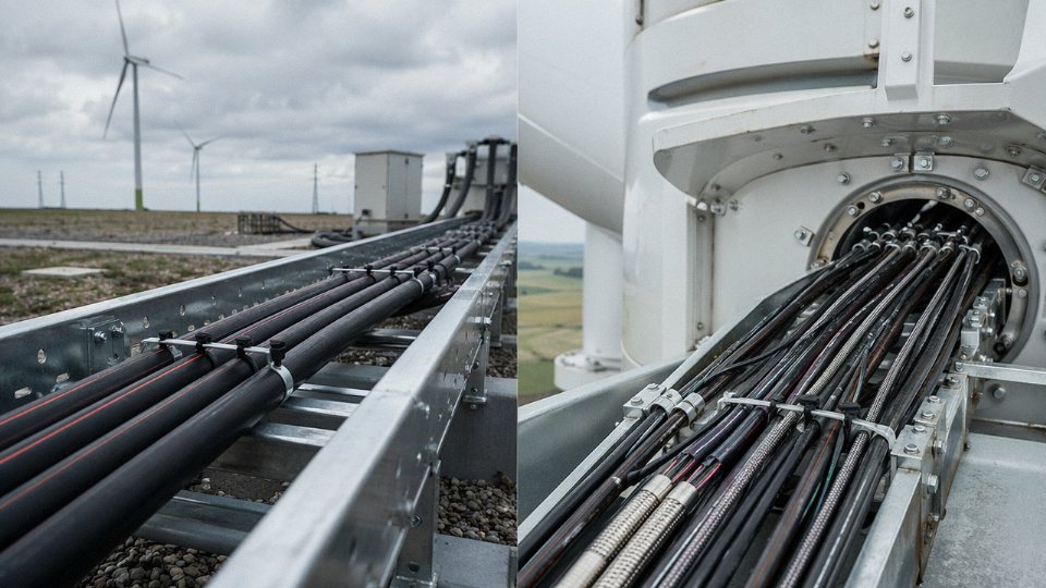
A wind farm’s electrical architecture uses both cable types in ways that are easy to confuse until you trace the signal path. The inter-array cable — typically a 33 kV XLPE design per IEC 60502-2 — carries generated power from turbine pad-mount transformers to the substation. Inside the nacelle, it’s a different world: flexible, shielded control cables connect the blade pitch controllers, yaw motor drives, and vibration sensors back to the turbine controller. These nacelle cables must survive continuous flexing as the nacelle rotates, which is why they use fine-stranded conductors and often a TPE or PUR outer sheath rather than PVC. Jinda supplies both the MV inter-array cable for the collection grid and the internal control cable bundles for turbine assemblies — a useful thing when a project team wants to consolidate vendor qualifications.
Industrial Manufacturing and Automated Assembly
In a plant running CNC machine tools, robotic welding cells, or induction furnaces, power and control cables coexist in very close quarters. Power cables — often 0.6/1 kV multicore, sized anywhere from 16 mm² to 185 mm² depending on the load — feed the machine panels. Control cables handle the PLC I/O, servo drive feedback, safety light curtain connections, and HMI communications. Most machine-builder standards, and any decent cable management design, enforce a minimum 200 mm separation between the two cable trays, or a grounded metal divider if space forces them into the same enclosure. Ignore that and your servo drive will thank you with encoder errors and nuisance faults, usually on a Monday morning after a weekend shutdown cycle when the plant is coldest.
A minimum physical separation of 200 mm between power and control cable trays significantly reduces EMI-induced signal errors in industrial automation environments.True
This figure is referenced in IEC 61000-5-2 and widely adopted in machine-builder cable management guidelines; the actual required separation depends on cable shielding quality and the voltage/current magnitude of the power cable, but 200 mm is the accepted practical minimum for unshielded control cables adjacent to low-voltage power feeders.
Building Services: Data Centers, Hospitals, High-Rise
Here the critical distinction shifts from EMI segregation to fire performance. Power cables at 0.4 kV distribute UPS output to PDUs and critical loads — typically LSZH-sheathed for smoke management, but not necessarily rated for circuit integrity under fire. The fire alarm and suppression system control cables are a different specification entirely: IEC 60331 circuit integrity under fire is mandatory, meaning the cable must maintain electrical function for 30, 60, or 90 minutes while burning. Confusing a standard control cable with an IEC 60331-rated fire-resistant cable in a hospital installation is the kind of specification error that fails a building inspection at best, and enables a life-safety failure at worst.
Rail and Transit Infrastructure
Traction power cables at 25 kV AC or 750 V DC are massive, heavily insulated conductors — nothing subtle about them. The signaling and train control cables running alongside (ETCS, ATP) are the opposite: small-cross-section, individually screened pairs, designed to reject the severe electromagnetic environment that traction systems generate. In a rail project, the two cable families are specified under entirely separate standards, procured through different qualification chains, and installed by different subcontractors. The segregation is structural and contractual, not just a routing preference.
Mining and Quarrying: Trailing Cables
Mobile mining equipment — continuous miners, shuttle cars, LHDs — uses trailing cables that deserve their own category. The power portion typically carries 3.3 kV or 6.6 kV to the machine’s drive system. Within the same trailing assembly, a separate control cable element carries radio remote control signals and emergency stop circuits. Both elements share a common outer sheath for mechanical protection, but they are electrically segregated internally. That shared sheath sees dragging, crushing, and repeated coiling over the machine’s working life, which is why trailing cable construction — usually EPR insulation, CSP or PCP sheath — differs substantially from a fixed-installation power cable. Specifying a standard armored power cable for a trailing application is a maintenance headache waiting to happen.
The Five Most Costly Mistakes When Substituting One Cable Type for the Other
These mistakes show up repeatedly on industrial projects — in the commissioning punch list, in the insurance report after a fire, or quietly buried in a contractor’s contingency budget. None of them are exotic failure modes. They are all predictable, and most are avoidable at the specification or purchase-order stage.
Mistake 1 — Running Control Cable on a Power Circuit
Control cable insulation walls are thin by design, often around 0.6 mm, because the application does not demand more. That is fine at 300/500 V on a signal circuit. It is not fine on a 400 V motor feeder where switching transients routinely spike well above the rated voltage for microseconds at a time. Those transients erode the insulation from the inside. Meanwhile, the conductor itself — typically 0.75 mm² or 1.5 mm² — cannot carry the load current without heating up. Insulation softens, carbonizes, and you get a ground fault. Downstream consequences: arc flash, fire suppression activation, NEC and IEC non-compliance, and an investigation that will eventually trace back to the cable specification. In a food processing facility or petrochemical plant, that sequence also means an insurance claim and a production stoppage measured in days, not hours.
Mistake 2 — Using Power Cable for Long Control Circuit Runs
The instinct here is usually “bigger is safer,” which is understandable but wrong in this context. A 6 mm² or 10 mm² power cable on a 24 V DC control circuit costs far more per meter than a 1.5 mm² control cable, and that premium adds up over several hundred meters of PLC wiring. The more insidious problem is termination quality. Power cable conductors are stiff. They do not bend neatly into a 6 mm terminal block, the ferrule sits at an angle, and over time the contact resistance climbs. Intermittent relay dropout caused by a marginal terminal connection is genuinely one of the most time-consuming faults to diagnose on a live plant. Technicians chase the relay, the PLC card, the power supply — the cable is usually the last thing anyone checks.
Mistake 3 — Skipping Shielded Control Cable in VFD-Heavy Installations
Variable-frequency drives are everywhere now, and they generate high-frequency common-mode noise continuously during operation. Unshielded control cables routed in the same trunking as VFD output cables pick up that noise capacitively. The result is spurious signals on PLC digital inputs, phantom alarms, and erratic speed references on adjacent drives. The frustrating part is that this often does not show up during static commissioning — only once the plant is running at load. Retrofitting shielded cable after the trunking is installed and the cable trays are packed is expensive and disruptive. Specifying OS (overall screen) or individually screened pairs at the design stage costs maybe 15–25% more per meter, depending on core count and screen type. That premium is trivial compared to a post-commissioning retrofit.
Mistake 4 — Applying the Same Armor Specification to Both Cable Types
Over-armoring a 1.5 mm² control cable with heavy steel wire armor adds cost, reduces flexibility, and makes routing through conduit entries and glands unnecessarily awkward. Under-armoring a 150 mm² power cable in a direct-burial trench where soil movement or ground-loading is possible is a mechanical failure waiting to happen — sometimes years later, which makes root-cause analysis difficult. Armor weight needs to match the physical environment and the conductor size. A blanket “SWA on everything” specification written by someone who did not think about cable diameter is a procurement shortcut that creates installation problems.
Mistake 5 — Confusing Voltage Markings on the Purchase Order
This one is almost embarrassingly simple, yet it clears procurement review more often than it should. The designations “450/750 V” and “0.6/1 kV” look numerically similar to someone scanning a line item quickly. One is a control cable voltage rating; the other is the entry-level power cable rating under IEC 60502. They are not interchangeable. A cable purchased to the lower rating will fail third-party inspection for a power circuit application and require complete replacement — at the contractor’s cost, usually under time pressure.
Jinda's order acknowledgment process includes a specification cross-check step that flags voltage rating mismatches before manufacture begins.True
This is a stated internal process from the manufacturer's own project persona and procurement workflow description, presented as a manufacturer claim rather than an independently verified industry fact.
Procurement managers should build a simple verification step into their own workflow regardless: require that the cable voltage rating on the data sheet matches the voltage rating in the project specification, and make that a sign-off field on the purchase requisition. Thirty seconds at the desk prevents weeks of rework on site.
How to Read a Cable Specification Sheet and Data Sheet: A Field Engineer’s Quick Reference
A data sheet looks straightforward until you’re standing in a procurement meeting with three competing offers printed out and no clear way to tell whether they’re actually quoting the same thing. They usually aren’t. Here’s how to read the numbers properly.
Voltage Designation Block: U₀/U/(Um)
The voltage block is the first thing to check, and it trips people up more than it should. U₀ is the rated voltage from conductor to earth (or screen), U is the rated voltage conductor-to-conductor, and Um is the highest system voltage the cable is designed to withstand — essentially the ceiling for the network it operates in.
Power cable data sheets will list all three. A typical 6/10 kV medium-voltage cable, for instance, shows U₀/U = 6/10 kV and Um = 12 kV. Control cable sheets often only state U₀/U — something like 300/500 V — because Um is largely academic at those voltage levels and not always tested or certified separately. If a supplier’s control cable sheet is missing Um, that’s not automatically a red flag. If a power cable sheet is missing it, ask questions before you sign off.
Conductor Class per IEC 60228
IEC 60228 defines four classes that matter in practice: Class 1 (solid), Class 2 (stranded), Class 5 (flexible), and Class 6 (highly flexible). For power feeders running fixed routes — underground duct, cable tray, direct burial — Class 2 stranded is standard and gives the best combination of current capacity and mechanical stability. Control cables destined for panel wiring or machine tool connections typically specify Class 5, because they need to tolerate repeated flexing during installation and occasional repositioning.
Class 6 is reserved for things like hand-held equipment and drag chains. Don’t let a supplier quietly substitute Class 2 into a flexible-duty application to cut cost on fine-wire stranding — it will work until the cable fatigues at a bend point, usually inside a cabinet where nobody spots it until something trips.
Jinda marks conductor class clearly on the drum label and in the data sheet, which makes incoming inspection faster.
Temperature Rating Column
This column is easy to overlook when you’re buying cable in a temperate climate. Standard PVC insulation is rated roughly –15 °C to +70 °C continuous conductor temperature. XLPE pushes that to around –40 °C to +90 °C, which also improves current capacity because the insulation handles heat better. Silicone rubber extends the upper limit to +180 °C, relevant near furnaces or engine compartments.
For Arctic or sub-Arctic installations, neither standard PVC nor standard XLPE is acceptable at ambient temperatures below –40 °C — you need cables specifically rated to –50 °C or lower, with cold-crack-tested outer sheaths. Specifying the wrong low-temperature rating is the kind of mistake that doesn’t show up until the first hard winter, when cable jackets start cracking during manual handling on-site.
Electrical Test Parameters
Power cable data sheets must include the AC voltage test value (Ud), DC resistance at 20 °C per conductor, and insulation resistance (typically expressed in MΩ·km). These are the three you need for acceptance testing.
Control cable sheets should carry all of that, plus — critically — mutual capacitance in pF/m, conductor-to-conductor resistance unbalance percentage, and for shielded types, shield coverage percentage and transfer impedance. Mutual capacitance matters for long signal runs where capacitive loading distorts analog signals or slows digital edges. Resistance unbalance affects bridge circuits and differential measurements. If you’re buying shielded control cable and the data sheet doesn’t state transfer impedance, the supplier probably hasn’t tested it.
Weight and Outer Diameter
These two values feed directly into structural calculations, and engineers sometimes treat them as afterthoughts. A 37-core 1.5 mm² shielded control cable can weigh somewhere in the range of 1.1–1.4 kg/m depending on sheath material and shield type, with an outer diameter around 26–30 mm. Run 20 of those across a cable ladder rated for 50 kg/m and you’ve used the entire allowance before you’ve added a single power cable.
Conduit fill ratios are similarly affected. Most codes limit fill to around 40% of conduit cross-sectional area for three or more cables — a number that’s easy to blow through if you’re working from nominal diameters rather than actual data sheet dimensions.
Drum Length: Standard vs. Custom
Standard drum lengths for control cable are typically 100 m, 200 m, or 500 m. Medium-voltage power cables usually come on 500 m or 1,000 m drums, though actual length depends on cable diameter and drum geometry. The practical issue is field joints: every joint in a power cable run is a potential failure point and an installation cost. On large infrastructure projects — say, a long substation feeder or an offshore platform home run — custom drum lengths that eliminate mid-run joints pay for themselves quickly against the cost of joint kits and the labor and test time they require.
Jinda offers custom drum lengths to minimize field joints on large infrastructure projectsTrue
Custom drum winding is a documented manufacturing capability that large cable producers offer to reduce the number of field splices required on extended cable runs, lowering installation cost and long-term reliability risk.
When comparing supplier offers, always normalize drum length to a per-meter price and confirm whether the quoted length is nominal or guaranteed minimum. Tolerance on stated drum length is typically ±0% to +5% in most standards, but that needs to be written into the purchase order if it matters for your cut schedule.
Frequently Asked Questions About Power Cables and Control Cables
Can I use a control cable as a power cable if the voltage is low enough?
No — and this substitution causes real damage, usually within hours. The voltage rating might technically match, but control cable insulation is type-tested for signal-level duty, not sustained load current. Run 10 A through a 1.5 mm² control cable core that was never designed for continuous thermal loading and you will exceed its safe operating temperature long before any protection device trips. The conductor heats, the insulation softens, and in a bundled multi-core cable the heat has nowhere to go. Use a cable rated for its actual electrical duty. Always.
Control cable insulation is not tested or rated for sustained current-carrying duty under IEC standards governing power cables such as IEC 60502.True
IEC 60502 defines current-carrying capacity testing and construction requirements specific to power cables; control cable standards such as IEC 60227 and IEC 60245 do not require or verify these same thermal performance benchmarks, making substitution electrically unsafe.
Why do control cables sometimes have 48 cores or more?
Because modern machinery and process plant are genuinely that signal-dense. Each core serves exactly one discrete function — a motor run permissive, a valve open/close confirmation, an emergency stop loop, a lamp driver. A typical PLC cabinet controlling a pumping skid might need 30 to 40 individual switching signals running back to a local marshalling box, and that count climbs fast on a multi-drive system. Grouping all of them into one 48-core cable instead of running 48 separate singles cuts installation labor substantially, reduces cable tray fill, and makes fault-finding less of a nightmare. In practice, 12-core and 24-core are the most common plant stock sizes; 48-core tends to appear in main panel runs between an MCC and a remote I/O cabinet.
What is the difference between a control cable and an instrumentation cable?
They are related but not interchangeable. Instrumentation cable is a purpose-built subset designed specifically for analog measurement signals — 4–20 mA loops, 0–10 V references, thermocouple extension, RTD wiring. These signals are low-level and highly susceptible to induced noise, so instrumentation cable uses individually shielded twisted pairs or triads; each pair has its own foil or braid shield with a drain wire, which you terminate at one end only to avoid ground loops. A standard control cable, by contrast, carries digital switching signals that are relatively noise-immune, and may carry only an overall shield or none at all. Running a 4–20 mA flow transmitter signal through an unshielded standard control cable routed near a VFD is a reliable way to get erratic process readings.
How do I identify a power cable versus a control cable in an existing installation with no labels?
Start with the outer sheath. Every compliant cable has its voltage designation, applicable standard, and manufacturer name printed repeatedly along the jacket — if that’s worn off or missing, that’s itself a problem worth flagging. Then count cores and check sizes: three or four large-section conductors in standard phase colors almost certainly indicate a power cable. A bundle of small, sequentially numbered cores — 0.75 mm² to 2.5 mm², often with a common black or grey sheath — points to control cable. If you need to be certain, strip a short sample and measure insulation wall thickness with a micrometer; power cable insulation walls are measurably thicker relative to conductor diameter. Core color coding under IEC standards also differs systematically between the two families.
Does Jinda supply both power and control cables from the same order, and can they ship together?
Yes, and this is actually a common requirement from EPC contractors who cannot afford to manage two separate shipment schedules. Jinda’s five production bases in China allow both cable families to be manufactured, tested, and consolidated onto a single export shipment with coordinated documentation — one set of test certificates, one packing list, one bill of lading if the buyer needs it that way. For large project orders covering an entire bill of materials, this consolidation meaningfully reduces freight cost and customs complexity.
What minimum order quantity applies to control cables for international buyers?
Roughly 500 m per size per line item is Jinda’s typical starting point, though this is genuinely negotiable when a buyer is placing a full project BOM order covering multiple sizes simultaneously. A single-size spot order of 200 m is harder to accommodate on standard pricing; a project order totalling several kilometres across 15 sizes is a different conversation entirely. Contact Jinda’s international sales team with your full BOM and they will work from there.
Are LSZH versions of both cable types available, and when are they required?
Jinda produces LSZH (Low Smoke Zero Halogen) variants of both. The requirement is typically driven by the installation environment rather than the cable’s electrical function: enclosed public infrastructure — metro tunnels, airport terminals, offshore platforms — mandates LSZH because conventional PVC insulation releases dense smoke and hydrogen chloride gas when it burns, which is a life-safety issue in confined spaces where evacuation is slow. Data centers increasingly specify LSZH for the same reason. If your project specification or local building code references IEC 60332, IEC 61034, or IEC 60754, you need LSZH — confirm this before procurement, not after delivery.
How does armoring choice differ between power and control cables for direct burial?
Both types use SWA (steel wire armor) for direct burial mechanical protection, but the armor wire diameter scales with cable diameter and the tensile loads involved. A large three-core 240 mm² power cable typically uses armor wires around 3.5–4 mm diameter; a 12-core 1.5 mm² control cable uses wires closer to 0.8–1.0 mm. The protection mechanism is the same; the wire gauge is not, and you cannot inspect them as equivalent products just because both say “SWA” on the data sheet. For coastal installations, salt-marsh cable routes, or anywhere with consistent groundwater chloride exposure, Jinda recommends double-layer AWA (aluminum wire armor) on both cable types — steel wire armor in those environments corrodes faster than most operators expect, and you usually don’t find out until a fault occurs during a wet season.
Sourcing Power and Control Cables from Jinda: Production Capability, Quality Assurance, and Global Supply Chain
For EPC contractors assembling a cable bill of materials across multiple voltage classes, one of the quieter operational headaches is managing four or five different suppliers — each with different lead times, quality systems, and documentation formats. A single-source manufacturer that can cover LV power cables, MV XLPE cables, and the full range of control and instrumentation cables is genuinely useful, not just convenient.
Manufacturing Scale and Vertical Integration
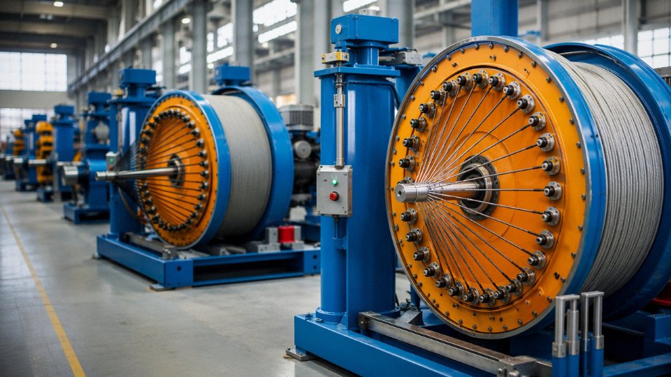
Jinda operates five production bases across China, with a combined manufacturing footprint of roughly 470,000 m². That scale matters less for its own sake than for what it enables: vertical integration from copper rod drawing and compound mixing — PVC, XLPE, and LSZH — through extrusion, stranding, armoring, and final drum testing, all under one quality management umbrella.
Why does integration matter to a procurement manager? Because most quality escapes in cable manufacturing don’t originate on the final extrusion line — they originate at sub-suppliers. A factory that buys in PVC compound, insulation tape, and pre-drawn copper from three different vendors has three more opportunities to receive an off-spec batch that slips through incoming inspection. Controlling those upstream steps internally closes that gap. In practice, this is the difference between a supplier who can explain a test failure and one who can actually prevent it from reaching your shipping reel.
Product Range: LV Through MV, Power Through Instrumentation
The product line covers 0.6/1 kV LV power cables up through 35 kV XLPE medium-voltage cables, alongside unshielded control cables, overall-shielded cables, and individually shielded pairs and triads for instrumentation — all available in both PVC and LSZH jacket compounds. For a single substation or industrial plant project, that typically covers the entire cable schedule without splitting the order.
LSZH versions, in particular, are increasingly specified for offshore platforms, data centers, and metro rail projects where smoke density and halogen acid gas emission during a fire are contractually restricted. Having both compound options in-house means the lead time doesn’t jump by six weeks when a late project specification change mandates LSZH.
Quality System and In-House Testing
The quality management system is ISO 9001 certified. The in-house test laboratory runs high-voltage withstand tests, partial discharge measurement, conductor resistance verification per IEC 60228, tensile and elongation testing on insulation and jacket compounds, and flame propagation testing to the IEC 60332 series. Partial discharge capability is worth calling out specifically — many factories at this price tier lack it, which means MV cable PD testing gets outsourced, adding time and reducing traceability.
Third-party witness testing by SGS, Bureau Veritas, and TÜV Rheinland is available on request for Jinda cable production.True
Jinda offers third-party inspection and witness testing by accredited international bodies including SGS, Bureau Veritas, and TÜV Rheinland, which is standard practice for internationally traded cable where end-client specifications require independent verification.
For projects requiring destination-country certification — CE marking under the CPR, GOST R for CIS markets, or GB/T for domestic Chinese installations — Jinda’s technical team can identify the applicable standard and provide the corresponding test reports for customs clearance and commissioning documentation. That assistance is underappreciated until you’re two weeks from a project deadline and your freight agent is asking for documents you didn’t know you needed.
Export Logistics and Documentation
Cables ship on non-returnable wooden drums or steel reels, sized and braced for sea freight. Fumigation certificates, phytosanitary documentation, and English-language packing lists are standard, not exceptions requiring special requests. Jinda ships to more than 50 countries and works with freight forwarders experienced in handling oversized reels — both FCL and LCL, depending on order volume. That logistics experience matters when a port authority in a destination country has specific drum weight or dimension restrictions that a less experienced exporter wouldn’t anticipate until the container is already loaded.
Technical Support Structure
A dedicated international technical support team handles cable selection queries, drum schedule preparation, and installation guidance. Factory audits and production surveillance visits are actively welcomed — not reluctantly accommodated. For long-term supply partnerships on multi-phase projects, that openness to on-site inspection is usually a more reliable quality signal than any certificate.