Specifying armored cable for an above-ground run and then finding out mid-project that your support spacing is wrong, or that nobody budgeted for UV-rated oversheath, is the kind of problem that shows up as a warranty dispute or an early insulation failure — not immediately, but three winters later when you’re tracing why a production line keeps tripping. The rework cost alone, pulling cable off a cable tray and re-running it with proper cleats, can easily run two to four times the original installation labor depending on access and plant layout.
Yes, you can run armored cable above ground. SWA and similar armored cables are routinely installed on cable trays, ladder racks, wall brackets, and overhead supports in industrial and utility settings. The armor provides mechanical protection, but above-ground service introduces UV exposure, thermal cycling, and vibration that buried runs don’t face — so correct support spacing, cleat selection, and oversheath specification are non-negotiable for a service life in the 25–40 year range.
What makes above-ground armored cable installation genuinely tricky isn’t the cable itself — it’s the gap between what the standards say and what actually gets built on a plant floor under schedule pressure. The bending radius rules, the support intervals, the difference between a cable that survives five years and one that’s still performing at thirty: all of it comes down to decisions made before the first cleat goes on the wall.
Armored Cable Construction: What the Layers Actually Do Above Ground
Start from the center and work outward — each layer earns its place, and above ground, the load on each layer shifts compared to buried service.
Conductor: Copper or Aluminum, and Why It Matters Topside
The conductor is either stranded copper or stranded aluminum. Copper gives you higher conductivity per cross-section (roughly 58 MS/m versus aluminum’s 35 MS/m), which matters when conduit space is tight or ampacity is the binding constraint. Aluminum, at about 30% of copper’s weight for the same cross-section, becomes genuinely attractive in aerial or catenary runs where cumulative sag over a 20–40 m span would otherwise put real tensile load on every support bracket. The conductor itself contributes nothing to mechanical protection — its role above ground is purely electrical, though in larger sizes (say, 150 mm² and up) the thermal mass does affect how quickly the cable responds to fault currents, which becomes relevant if the run is exposed to direct sun and ambient temperatures are already pushing the insulation’s rated limit.
Insulation: XLPE Holds Up Where PVC Softens
Cross-linked polyethylene (XLPE) insulation is the better choice for above-ground use in almost every scenario I can think of. It handles continuous operating temperatures up to around 90°C, survives short-circuit thermal spikes better, and doesn’t plasticize and creep the way PVC does when a cable is sitting in direct sun on a summer afternoon in, say, a steel plant yard. PVC insulation is rated to roughly 70°C — workable in many indoor above-ground routes, but marginal in outdoor unshaded runs in hot climates. The insulation’s primary job is dielectric; above ground it also needs to resist any moisture that works its way in from damaged outer layers over a 25–40 year service life, which is one more reason XLPE’s lower water absorption rate matters here.
Inner Sheath: The Bedding Layer You Shouldn’t Overlook
This extruded layer — typically PVC or a rubber compound, 1–3 mm thick depending on cable size — beds the armor wires and protects the insulation cores from mechanical damage caused by the armor itself moving under load. Above ground, where a cable on a tray or catenary wire flexes with thermal expansion or wind, the inner sheath absorbs that relative movement. Skip quality here and the armor wires eventually abrade through to the insulation cores. It happens slowly, invisibly, and then you get an insulation fault nobody can immediately explain.
Armor Layer: SWA, STA, or AWA — Pick the Right One
This is the selection decision that most directly determines whether the cable survives above-ground service.
Steel wire armor (SWA) uses helically wound galvanized steel wires, typically 1.6–4.0 mm in diameter depending on cable OD (which itself ranges from roughly 10 mm for a 1.5 mm² cable up to 85 mm for a 630 mm² cable). SWA provides genuine tensile strength — relevant for vertical risers, catenary suspension, and any run where the cable is partially self-supporting. It also handles accidental impact well: a forklift clip or a dropped tool that would split a plain sheathed cable may leave SWA intact.
Steel tape armor (STA) is two overlapping helical steel tapes rather than individual wires. It resists radial crush well and is fine for horizontal tray work where the cable is fully supported, but it has almost no tensile capacity. Don’t use STA for vertical runs or aerial spans. The failure mode — tape layers separating under longitudinal load — tends to show up months after installation when the armor has fatigued at the first support point.
SWA armored cable provides significantly higher tensile strength than STA for above-ground vertical or catenary installationsTrue
SWA uses continuous helical steel wires that distribute tensile load along the cable's length, while STA consists of overlapping flat tapes that offer radial crush resistance but minimal tensile load capability — a distinction confirmed by IEC 60502 construction requirements and standard engineering practice for supported cable runs.
Aluminum wire armor (AWA or AWAC) solves two problems at once for single-core above-ground cables. First, it weighs roughly 40–50% less than equivalent SWA, reducing sag in aerial spans and lightening the load on cable trays and brackets — meaningful when you’re running 50 m of 95 mm² cable across an outdoor gantry. Second, and this is critical for single-core AC circuits: steel armor in a single-core cable creates a closed magnetic path that causes hysteresis losses and can cause the armor to heat continuously under load. Aluminum, being non-magnetic, eliminates this entirely. For three-core or multicore cables the magnetic fields largely cancel and SWA is fine; for single-core, AWA is the technically correct choice.
Outer Sheath: UV, Temperature, and Smoke Class
The outer sheath is the first line of defense above ground and it takes the full environmental load.
PVC is standard and cost-effective, but its UV resistance is mediocre. Unmodified PVC outer sheaths can become brittle and crack within 5–8 years of direct outdoor sun exposure — faster in equatorial climates. Suitable for indoor above-ground routes or outdoor runs where the cable is shaded or conduit-run most of the way.
Polyethylene (PE) is the correct choice for continuous outdoor above-ground exposure. Carbon-black-loaded HDPE outer sheaths handle UV well, remain flexible at low temperatures (down to around −40°C in some formulations), and shed water cleanly. This is what you want on a rooftop cable tray or an outdoor overhead run.
LSZH (Low Smoke Zero Halogen) sheaths are specified wherever above-ground cables pass through occupied or partially enclosed spaces — substations, cable basements, generator rooms — where a cable fire must not generate toxic halogenated gases or dense smoke that prevents evacuation. LSZH sheaths typically have slightly lower UV resistance than PE, so for routes that combine outdoor exposure and indoor passage, make sure the specification calls out both UV stabilization and LSZH compliance explicitly rather than assuming one implies the other.
Above-ground service life of 25–40 years is achievable — but that figure depends heavily on getting the outer sheath material right for the specific exposure conditions, maintaining minimum bending radii (8–12× overall cable diameter per IEC 60502 and BS 6346, depending on armor type), and supporting the cable at intervals that prevent sustained tensile load on any single point. The construction choices described above aren’t academic; they’re what separates a cable still performing cleanly in year 30 from one you’re replacing in year 8.
International Standards and Codes Governing Above-Ground Armored Cable Installation
Regulatory compliance for above-ground armored cable runs is not a single standard — it’s a layered matrix of product standards, installation codes, and regional authority requirements. Getting this wrong costs money in two directions: over-specified cable that inflates procurement cost, or under-specified cable that fails inspection and forces rework. Here’s how the major frameworks actually interact.
IEC 60502: The Product Foundation
IEC 60502 Parts 1 and 2 define the construction and testing requirements for armored power cables rated from 1 kV up to 30 kV. Part 1 covers cables up to and including 1 kV; Part 2 handles the medium-voltage range from 3.6/6 kV to 20.8/36 kV. For above-ground use, the relevant sections deal with armoring material verification (steel wire or steel tape), conductor resistance, voltage withstand testing, and the insulation and oversheath requirements that determine UV and mechanical performance once the cable is exposed.
What the standard does not prescribe is how you physically mount the cable in service. That’s intentional — IEC 60502 is a product standard, not an installation code. A cable can be fully IEC 60502-2 compliant and still be installed incorrectly if the support spacing, bending radius, or thermal environment aren’t handled properly.
IEC 60502 compliance alone is sufficient to ensure a safe above-ground armored cable installationFalse
IEC 60502 is a product standard covering construction and testing. Safe above-ground installation also requires compliance with installation codes such as IEC 60364-5-52, national wiring regulations, and local authority requirements for support spacing, derating, and UV protection.
IEC 60364-5-52: Where Installation Method Meets Current Capacity
This is the standard that drives actual design decisions on the plant floor. IEC 60364-5-52 tables define reference installation methods — cables on perforated trays, in free air, clipped to surfaces, inside conduit — and attach derating factors to each. For above-ground grouped armored cables on a cable tray, grouping derating factors can drop your allowable current capacity by 30–50% depending on the number of circuits and whether they’re touching or spaced. Support spacing guidance in this standard is typically in the range of 350–500 mm for vertical runs and 700–900 mm for horizontal runs on cleats, though the exact interval depends on cable weight (diameter ranges from roughly 10 mm for 1.5 mm² SWA up to 85 mm for 630 mm² SWA makes a significant weight difference) and the manufacturer’s recommendation.
BS 7671 (18th Edition): UK Specifics
British installations follow BS 7671, which references Method C (clipped direct to a surface) and Method E (free air, single layer on a tray). The current-carrying capacity tables in Appendix 4 are keyed to these methods, and the difference between them matters — Method E typically allows 10–15% higher continuous current than Method C for the same armored cable cross-section, because free air circulation improves heat dissipation. UK projects also need to account for Appendix 4 correction factors for ambient temperature; a cable tray running through an unventilated plant roof space in summer can see ambient conditions well above the 30°C reference temperature.
NEC Article 330: US Requirements for MC Cable
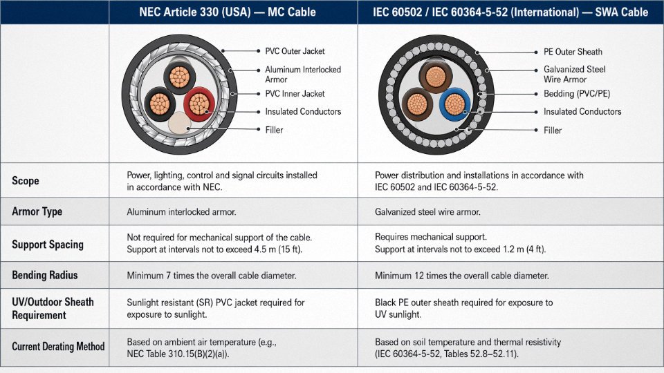
In the United States, Metal-Clad (MC) cable governed by NEC Article 330 is the closest equivalent to SWA in common above-ground industrial use. Article 330.30 sets a maximum support interval of 6 ft (roughly 1.8 m) between cable supports or staples, with supports required within 12 inches of every box, fitting, or termination point. Above-ground exposed runs are explicitly permitted under NEC 330.10, provided the cable is protected from physical damage where subject to it — which in practice means conduit sleeves or guards at any location below roughly 2.5 m above the floor in a working area.
One common mistake on US projects using imported IEC-rated SWA: the NEC doesn’t automatically recognize IEC 60502 certification as equivalent to a UL listing. The local AHJ has discretion here, and in practice this varies significantly by jurisdiction and inspector. Some will accept a third-party evaluation report; others won’t. Sort this out before the cable ships, not after.
EN 50565 and European Industrial Fixed Installations
EN 50565 covers application guidelines for cable management in fixed electrical installations across European markets. For above-ground industrial runs, it references cable tray systems, cleat selection, and mechanical protection requirements in ways that complement IEC 60364-5-52. In most EU member states, the local transposition of these harmonized standards carries legal force under low-voltage directive requirements, so “EN-compliant” isn’t just a badge — it’s a procurement specification with legal consequences on public and commercial projects.
GB/T 12706: Jinda Product Compliance and IEC Alignment
China’s national standard GB/T 12706 (covering armored power cables up to 35 kV) is technically harmonized with IEC 60502 to a high degree. The construction requirements, test voltages, and conductor specifications map closely, which means Jinda cables manufactured and tested under GB/T 12706 can typically be evaluated against IEC 60502 requirements for international project certification. The practical implication for procurement engineers sourcing from China for international projects: request test reports issued against both GB/T 12706 and IEC 60502, confirm conductor stranding class matches your IEC 60228 requirements, and verify the third-party certification scope explicitly covers the armoring construction you’re specifying.
Compliance in Practice: The AHJ Problem
The hardest part of cross-border cable procurement isn’t the standards — it’s the local authority having jurisdiction. An IEC 60502-certified SWA cable is a known quantity to an engineer in the UK, Germany, or Australia. The same cable arriving at a US, Canadian, or Middle Eastern project site may require additional documentation, field evaluation, or re-testing before an inspector signs off. Build this verification step into your procurement timeline. Waiting until installation is underway to discover that your IEC-certified cable needs a UL evaluation report can add weeks to commissioning — and a few thousand dollars in expedited testing fees is cheap compared to the cost of a delayed production startup.
Support Systems, Cleat Spacing, and Mechanical Requirements for Above-Ground Runs
Getting the support system right is where above-ground armored cable installations either hold up for thirty years or start causing problems within the first operational season. The mechanical demands are genuinely different from buried runs — thermal cycling, wind loading, vibration, and the need to resist fault-current forces all interact in ways that catch out engineers who treat surface and aerial work as an afterthought.
Cable Tray Selection and Fill Ratios
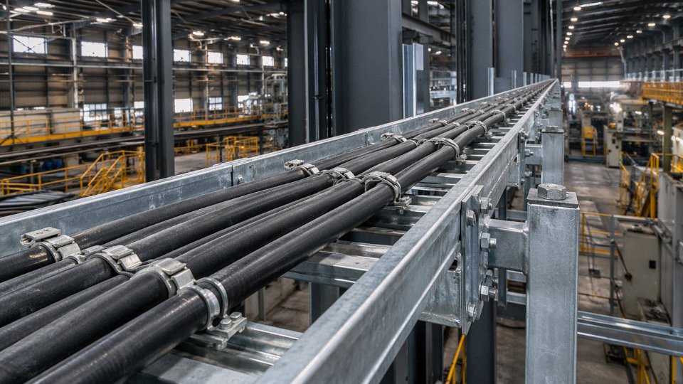
Ladder tray is the default choice for most industrial above-ground runs, and for good reason: it allows airflow around grouped cables, which directly affects current-carrying capacity. Solid-bottom tray is used where you need debris protection or where dropping a small fitting into live equipment below is a real hazard — processing plants, for instance. The trade-off is that solid-bottom tray traps heat, so your ampacity derating factors apply more aggressively.
Fill ratio is the figure most procurement engineers underestimate. IEC 61537 caps usable fill at roughly 50% of tray cross-sectional area for grouped power cables — not because the tray can’t physically hold more, but because exceeding that threshold drives thermal derating that can negate the cost of the larger conductors you specified. Tray load capacity depends on span and material: galvanized steel tray handles roughly 75–150 kg/m run-load depending on gauge and rung spacing; aluminum tray is lighter but deflects more under heavy SWA bundles; FRP (fiberglass-reinforced polymer) tray is the right call in coastal, chemical, or offshore environments where zinc coating would be attacked within a few years. Don’t let purchasing swap FRP for galvanized on cost alone in a chloride-rich environment — the corrosion replacement cycle will cost more than the tray premium.
Cleat Selection and Short-Circuit Force Calculations
IEC 61914 governs cable cleat selection, and the central requirement is that cleats must restrain cables against the electromagnetic forces generated during a fault. These forces are not trivial. For a 3-core 95 mm² SWA cable at a prospective fault current of 40 kA, the peak electromechanical force between conductors runs in the range of 8–15 kN/m of cable length, depending on conductor spacing and the actual peak-to-RMS ratio of the fault waveform. That figure drives cleat material choice: a plastic push-in cleat rated for standard service loads will fail under those conditions. You need metallic or reinforced-polymer cleats with a published short-circuit test rating at or above the installation’s prospective fault level. Specify this in your procurement documents, not as a verbal instruction on site.
Spacing Benchmarks for Horizontal and Vertical Runs
For horizontal runs, cleat spacing on directly-mounted or wall-mounted SWA cable typically falls in the 500–900 mm range. Tray support steelwork (the hangers or brackets carrying the tray itself) is usually at 900–1,200 mm centers, though heavier cable loads push you toward the closer end. Vertical runs are a different story — cable weight accumulates, and without adequate support, the armor wires carry tensile load they weren’t designed for over long vertical distances. BS 6346 and IEC 60502 both call for reduced spacing on vertical runs; in practice this means cleats at 300–500 mm intervals on vertical sections, sometimes with a strain relief cleat at the bottom of the run.
Minimum bending radius for multicore SWA cable is 8× the overall cable diameter, and 12× for single-core SWA, per IEC 60502 and BS 6346.True
Single-core cables lack the mechanical symmetry of multicore constructions and are more susceptible to armor wire stress and insulation damage at tight bends; IEC 60502-2 and BS 6346 both reflect this with the higher multiplier for single-core.
Termination points are where bending radius violations usually happen — an installer trying to make a neat entry into a gland plate under a panel. A 35 mm overall diameter SWA cable needs a minimum bend radius of 280 mm for multicore, 420 mm for single-core. Violating this doesn’t cause immediate failure in most cases, which is exactly what makes it dangerous: insulation stress and armor wire distortion accumulate quietly until a fault or thermal cycle finishes the job.
Aerial Spans and Catenary Installation
Self-supporting armored cable or messenger-wire-supported runs are used where trenching or tray is impractical — inter-building runs across a yard, for example. Typical industrial aerial spans in my experience run 15–40 m, with the actual maximum depending on cable weight per meter, the sag allowance you can live with, and wind/ice loading at the site. A heavier 3-core 185 mm² SWA cable can run 60–80 kg per meter of span at full sag load; exceed the span without a proper catenary calculation and you’ll pull apart terminations or stress the gland entry. For longer spans, dedicated messenger wire carries the mechanical load and the cable is lashed to it at 300–600 mm intervals.
Thermal Expansion and Surface Mounting
Above-ground cables see full ambient temperature swings — 40°C or more between winter night and summer afternoon in many industrial locations. Over a 30 m run, a PVC-sheathed cable can expand or contract 15–25 mm with that temperature range. Expansion loops or S-bends every 30–50 m absorb this movement and protect the terminations. Skip them, and you’ll eventually see cracked glands or pulled connections, usually at the worst possible time.
Surface-mounted cables on walls or structural steelwork need adequate standoff — typically 20–40 mm clearance behind the cable — to allow convective airflow and prevent heat buildup against the structure. Where cables penetrate fire compartment walls, intumescent sealing is mandatory regardless of the cable’s own fire performance rating; the penetration, not the cable, is the weak point in the barrier.
Environmental Hazards Specific to Above-Ground Armored Cable: UV, Heat, Chemicals, and Impact
Underground burial is, in some ways, a forgiving environment — stable temperature, no sunlight, limited mechanical interference. Put the same cable on a cable tray on a rooftop or along an exterior plant wall, and the degradation mechanisms multiply fast. Each hazard below has a specific material or design countermeasure; ignoring any one of them usually shows up as premature sheath cracking, reduced ampacity, or an unplanned outage.
UV Degradation
Standard black PVC outer sheaths contain carbon black as a UV stabilizer, but it’s rarely formulated to outdoor-exposure duty. In practice, untreated or lightly stabilized PVC begins to embrittle and surface-crack after roughly 3–5 years of continuous direct solar exposure — earlier in high-UV climates like the Middle East or equatorial Southeast Asia, somewhat later in northern Europe. Once the sheath cracks, moisture tracks down into the armor layer and you have a corrosion problem on top of a UV problem.
UV-stabilized polyethylene (PE) compounds and LSZH (Low Smoke Zero Halogen) outer sheaths formulated for outdoor use extend service life to 25 years or beyond — the exact figure depends on UV irradiance at the installation latitude and whether any shading occurs. IEC 60811-401 defines the accelerated UV aging test: cables are exposed to xenon arc radiation at specified irradiance levels, and tensile strength retention after exposure should not fall below 70% of the original value. When specifying above-ground cable for any outdoor run, ask your supplier for the IEC 60811-401 test certificate. If they can’t produce one, that’s your answer.
Thermal Loading
A cable sitting in a conduit underground sees stable soil temperature. A cable on an open tray in direct sunlight does not. Solar irradiance can push the outer sheath surface temperature 20–30°C above ambient air temperature — measured across installations in open process areas, that’s a real, repeatable delta, not a theoretical worst case. This forces derating of current-carrying capacity, typically in the range of 10–25% depending on grouping factor, tray fill, and geographic solar load. A three-cable bundle on a hot tray in a Gulf state petrochemical plant can require more aggressive derating than a single cable run on a shaded indoor tray in a temperate climate. Check the applicable derating tables in IEC 60502-2 or your regional standard and apply them before finalizing conductor cross-section.
Chemical and Oil Exposure
In petrochemical, mining, and food processing environments, the outer sheath faces hydrocarbon vapors, cleaning agents, lubricants, and occasional direct chemical splash. Standard PVC degrades in prolonged hydrocarbon contact — it swells, softens, and loses mechanical integrity. CSPE (Chlorosulfonated Polyethylene, often known by the trade designation Hypalon) and EPR (Ethylene Propylene Rubber) sheath compounds hold up significantly better in hydrocarbon-rich atmospheres and are worth specifying when the cable runs through or near pump stations, compressor skids, or CIP (clean-in-place) wash-down zones.
CSPE and EPR sheaths outperform standard PVC in continuous hydrocarbon vapor exposure above groundTrue
Both CSPE and EPR have documented superior resistance to oil, ozone, and chemical attack compared to standard PVC, supported by materials data in IEC 60092 and industry chemical resistance charts from major compound manufacturers.
Mechanical Impact and Abrasion
Manufacturing floors are not gentle environments. Forklifts clip cable trays. Angle iron edges abrade sheath during thermal expansion cycles. Tools fall. SWA armor provides meaningful impact resistance — IEC 60502 specifies minimum impact test energy values for the armor layer — but armor alone doesn’t protect against repeated low-energy abrasion against rough structural steel. Where routes pass through high-traffic zones or near moving equipment, add mechanical protection: galvanized steel conduit sections, cable protection guards, or purpose-built rubber impact guards over the tray. The armor is a backup; good routing and physical guarding are the primary defense.
Moisture and Condensation Cycling
Above-ground cables in outdoor or semi-outdoor locations go through daily wet-dry cycles, seasonal humidity swings, and in some climates, freeze-thaw. Each cycle stresses cable end terminations. Heat-shrink or cold-shrink termination kits rated to IP65 or better are not optional for outdoor above-ground ends — unsealed terminations allow moisture to track along the armor interstices and into the termination point, eventually causing insulation breakdown or armor corrosion from the inside out. This is one of those failures that takes two or three years to manifest and then looks like a cable defect when it’s actually an installation shortcut.
Vibration and Dynamic Loads
Cables routed on structural steelwork subject to wind-induced vibration, or within a few meters of large rotating machinery, face fatigue loading at cleat contact points. Standard cleats can act as stress concentrators if the cable vibrates against them repeatedly. Anti-vibration clamps with elastomeric liners distribute the load and damp movement. For SWA cables, armor wire fatigue is a real failure mode under sustained vibration — armor wires work-harden and eventually fracture at the cleat edge. If the installation is near a compressor hall or on an exposed rooftop structure in a wind-prone region, specify fatigue-rated armor wire construction and use vibration-dampening cleat systems.
Fire Performance for Indoor Above-Ground Routes
Where above-ground cables run inside occupied or process-critical buildings — control rooms, switchgear buildings, cable tunnels — fire performance requirements kick in regardless of whether the environment presents UV or chemical hazards. IEC 60332-3 covers flame propagation for bunched cables; IEC 60754 governs halogen acid gas emission; IEC 61034 addresses smoke density. LSZH armored cable is mandated in many facility types — offshore platforms, public infrastructure, data centers, densely cabled industrial facilities — where toxic smoke and halogen gas release during a fire creates an unacceptable evacuation or equipment damage risk. Standard PVC armored cable remains acceptable in open outdoor above-ground runs where fire gas dispersal is not a concern, but substituting it into an indoor route without checking fire performance classification is the kind of shortcut that gets flagged in audits.
Above-Ground Armored Cable in Specific Industrial Applications: Oil and Gas, Renewables, and Infrastructure
The gap between “armored cable can run above ground” and “here’s what that actually means on a specific project” is where most specification errors happen. Each sector below imposes its own layering of mechanical, chemical, electrical, and regulatory demands — and getting even one wrong usually means rework, downtime, or a failed inspection.
Oil and Gas Platforms and Refineries
Above-ground cable runs in Zone 1 and Zone 2 hazardous areas are probably the most demanding application armored cable faces. The armor itself isn’t the complicated part — it’s the sheath specification and the certification stack that consumes engineering time. LSZH (low smoke zero halogen) or CSPE compound outer sheaths are standard requirements, not optional upgrades, because toxic smoke in an enclosed topsides module or a refinery pipe rack is a life-safety issue. IEC 60079 Ex-e (increased safety) and intrinsic safety circuit cabling both require the cable construction to be fully documented and traceable to the rated installation category.
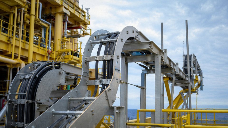
Voltage ratings in these environments typically run 0.6/1 kV for instrumentation and control loops up to 6.35/11 kV for main power distribution to compressor motors and high-voltage drives. The higher-voltage runs above ground on offshore topsides are usually in dedicated cable ladders with Ex-rated cleats — spacing tighter than a standard onshore tray because vibration from rotating equipment is a continuous load, not an occasional event.
Offshore and Coastal Installations
Salt spray is relentless and cumulative. Tinned copper conductors — not bare copper — are the correct choice for offshore SWA cable, because bare copper in a marine atmosphere will corrode at joints and terminations over a service life that should reach 25–40 years. Armor wire coatings need to be corrosion-inhibited; the outer sheath needs to pass IEC 60068-2-52 salt mist testing, which many standard-grade sheaths won’t survive at the more aggressive test severities.
Tinned copper conductors significantly reduce corrosion-related failure rates in offshore above-ground armored cable compared to bare copper conductors in salt mist environments.True
IEC 60068-2-52 salt mist testing and standard marine engineering practice both confirm that tinned conductor cables outperform bare copper in high-chloride atmospheric exposure, particularly at terminations and joints where bare copper oxidizes and increases contact resistance over time.
Wind Farm Cable Routes
Inside wind turbine towers, single-core aluminum wire armored (AWA) cable rated 6/10 kV up to 26/35 kV carries array power from the tower base to the nacelle connection. The engineering wrinkle that surprises people new to wind projects: the nacelle rotates, and over the turbine’s operating life that torsional movement is substantial. Cable management systems inside the tower have to accommodate that twist without fatiguing the armor wires or cracking the sheath. Bend radius margins during installation must be generous — usually toward the upper end of the 8–12× diameter range specified by IEC 60502. Running too tight here causes problems that won’t show up until year three or four.
Solar PV Utility-Scale Plants
Above-ground DC collector cables on racking structures need UV-resistant PE sheath compounds and, frankly, the lightest armor option the design can support — aluminum wire armor keeps the weight manageable on mounting frames not designed to carry heavy steel-armored cable runs across hectares of racking. Voltage ratings up to 1.8 kV DC per IEC 62930 apply to the string and combiner sections. Thermal cycling is severe; black sheath cables on exposed racking in high-irradiance climates see surface temperatures well above ambient on still days.
Rail, Transit, and Infrastructure
IEC 62440 and EN 50306 govern above-ground armored cable in rail environments. For cables inside tunnels or enclosed stations, fire performance isn’t just a line item — it determines which circuits survive long enough to support evacuation. Fire-resistant armored cable per IEC 60702 is specified for traction power and signaling circuits that must maintain circuit integrity under fire conditions, which is a fundamentally different requirement from simple flame retardance.
Industrial Manufacturing and Critical Power
In automotive or steel plant cable trays carrying hundreds of armored cables, the segregation discipline matters as much as the cable spec itself. Power, control, and instrumentation cables on separate tray runs isn’t overengineering — it’s how you avoid induced noise on 4–20 mA loops from adjacent VFD power cables, a failure mode that shows up as mysterious process upsets rather than obvious electrical faults. Data center main distribution circuits increasingly use fire-resistant SWA cable for the same reason rail does: some circuits simply have to keep running.
Termination, Jointing, and Grounding of Above-Ground Armored Cable
Termination errors account for a disproportionate share of above-ground armored cable failures. The cable itself may be perfectly specified and routed, then fail within two years because someone used the wrong gland, skipped the earth continuity check, or stripped the armor back a centimeter too far. These are not exotic problems — they show up in routine maintenance surveys, and they’re almost entirely preventable.
Armor Grounding Philosophy
For multicore SWA power cables installed above ground, bond the armor at both ends. Full stop. This gives you a low-impedance fault current return path and ensures the armor actually functions as a protective conductor under fault conditions rather than just sitting there looking like one. Single-end bonding is only appropriate on single-core cables operating above 1 kV, where bonding both ends would create a closed loop around a single-phase conductor — that loop sees the cable’s magnetic flux and drives circulating currents that heat the armor continuously, wasting energy and degrading the sheath over time. The rule is straightforward: multicore = both ends bonded; single-core MV/HV = one end only, with the remote end either isolated or connected through a sheath voltage limiter depending on the overvoltage exposure of the site.
Above-ground installations introduce one complication underground runs don’t face as severely: the armor earth bond at the gland entry point is exposed to vibration, thermal cycling, and sometimes corrosive atmosphere simultaneously. A loose earth tail on an outdoor gland that cycles through 40°C of daily temperature swing will eventually work loose. Use a locknut and spring washer on every earth tag, and torque it — don’t just finger-tighten.
Gland Selection for Outdoor Above-Ground Use
IP68-rated brass glands suit the majority of industrial above-ground applications. Where chloride atmosphere, acidic washdown, or coastal salt spray is present, specify 316 stainless steel — the cost difference is modest against the replacement labor if a brass gland dezincifies in three years. Gland sizing must match the cable’s actual outer diameter and the armor wire diameter; the clamping ring has to grip the armor wire layer, not the bedding below it or the oversheath above it. BS 6121 gives the dimensional basis for this selection.
Double-compression glands are the correct choice for outdoor above-ground installations without exception. A single-compression gland relies on one sealing point; thermal cycling breaks that seal progressively. Double-compression designs use independent seals on the cable outer sheath and on the armor clamping zone, maintaining IP rating after hundreds of thermal cycles and under the low-frequency vibration common near motors, compressors, and HVAC plant.
Termination Kits for Medium-Voltage Cables
Heat-shrink and cold-shrink termination kits both work above ground; the choice usually comes down on-site conditions and installer preference. Cold-shrink avoids open flame near the cable, which matters on petrochemical sites or anywhere with solvent atmosphere. Either way, stress control geometry at the screen cut-back is non-negotiable from 6 kV upward — without it, electric field concentration at the screen edge initiates partial discharge that erodes insulation over months or years before presenting as a fault. Termination kits must be voltage-class matched (1 kV, 6 kV, 11 kV, 33 kV) and comply with IEC 60840 for cables above 30 kV and IEC 82714 for the accessory qualification testing.
Straight-Through Joints Above Ground
Joints in above-ground runs need mechanical protection beyond the joint kit itself — a metal junction box rated minimum IP54, mounted rigidly to the cable support structure with anchor clamps on both cable runs to prevent the joint body from carrying thermal expansion loads. Resin-filled joints handle vibration better than heat-shrink in high-movement environments like elevated walkways or bridge crossings; heat-shrink joints work fine in stable, low-vibration runs. Either way, the armor continuity must be restored across the joint and verified during commissioning.
Common Termination Errors and Their Consequences
| Error | Immediate Result | Failure Mode |
|---|---|---|
| Under-stripping armor (nicking insulation) | No visible damage at install | Insulation breakdown under load, often within 6–18 months |
| Over-tightening gland body | Crushed armor wires, sheath deformation | Reduced fault current capacity; moisture ingress at crush point |
| Bending cable below minimum radius at gland entry | Internal conductor stress | Conductor fracture or insulation cracking under thermal cycling |
| Single-end bonding on multicore MV cable | Armor not continuous earth | Dangerous touch voltage on armor during fault |
| No double compression on outdoor gland | IP rating lost after first thermal season | Water ingress at termination, insulation degradation |
Post-Installation Testing
Before energizing, run an insulation resistance test — 500 V DC between conductors and between each conductor and armor for LV cables; 1,000 V DC for the insulation screen check on MV cables. Record the results. A healthy LV armored cable on a new installation should read well into the gigaohm range; anything below roughly 100 MΩ warrants investigation before you proceed.
High-voltage withstand testing per IEC 60502-2 applies to medium-voltage armored cables: the standard gives commissioning test voltages that are lower than factory test levels, typically around 80% of the type-test value, applied for a defined duration. This is a go/no-go check for installation damage, not a proof of design adequacy.
Finally, verify armor earth continuity with a low-resistance ohmmeter from gland to gland. It takes five minutes and catches the missed earth tail that would otherwise leave the armor floating — a safety hazard that creates genuine touch-voltage risk in the event of a phase-to-armor fault. This step gets skipped more often than it should on busy commissioning schedules.
Double-compression cable glands maintain their IP rating under thermal cycling and vibration better than single-compression glands for outdoor above-ground armored cable installations.True
Double-compression glands incorporate independent sealing elements at both the cable oversheath and the armor clamping zone, preventing seal relaxation under repeated thermal expansion and contraction cycles. This is consistent with BS 6121 gland performance requirements and is recognized practice in IEC and BS installation standards for outdoor industrial applications.
Cost Comparison: Above-Ground Armored Cable vs. Alternative Wiring Systems
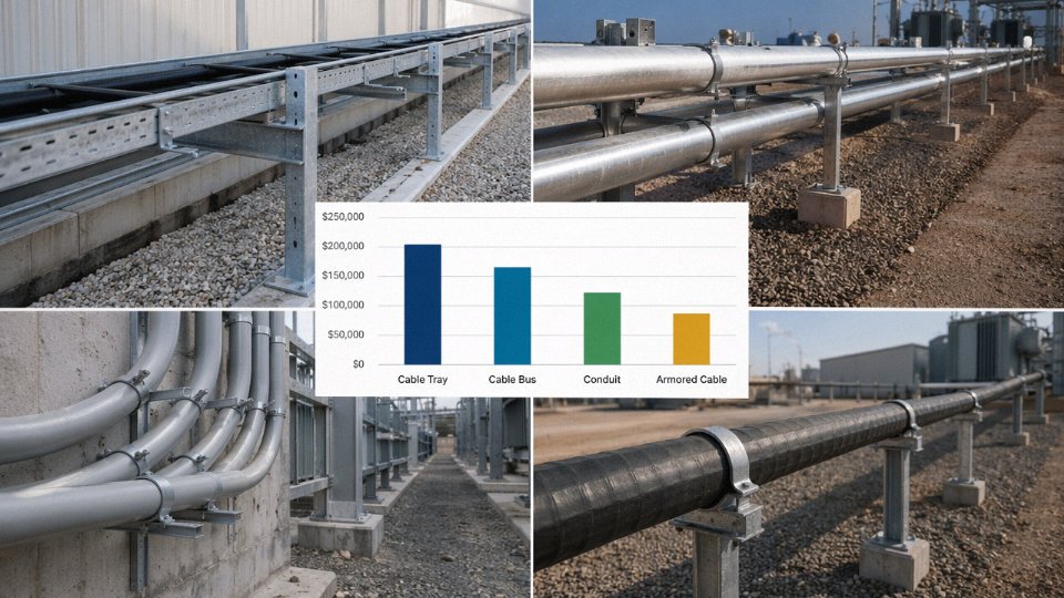
Choosing armored cable over conduit-and-wire or cable management duct isn’t just a technical call — it’s a procurement and lifecycle decision that shows up in your project budget and your maintenance log for the next three decades. The numbers below are realistic ranges based on a representative 4-core 16 mm² 0.6/1 kV circuit, 100 m above-ground run. Actual figures shift with local labor rates, steel prices, and site complexity, so treat these as planning-level estimates.
Direct Installed Cost Per Meter
For a 100 m above-ground run of this spec, rough installed costs typically look like this:
| System | Material Cost (per meter) | Labor Cost (per meter) | Approximate Installed Total (100 m) |
|---|---|---|---|
| SWA armored cable, open tray | $8–$14 | $4–$7 | $1,200–$2,100 |
| Unarmored cable in rigid steel conduit (RSC) | $6–$11 (cable + conduit + fittings) | $9–$15 | $1,500–$2,600 |
| Unarmored cable in PVC/steel cable management duct | $5–$9 | $6–$10 | $1,100–$1,900 |
| Mineral-insulated copper-clad (MICC) | $28–$55 | $12–$20 | $4,000–$7,500 |
Figures depend heavily on local labor rates (US Gulf Coast differs sharply from Southeast Asia), conduit size, and whether structural steel modifications are needed. The RSC system’s conduit threading and fitting installation — LB bodies, couplings, locknuts — adds time that most project schedulers underestimate by 20–30%.
The Labor Differential Is Real
In practice, eliminating conduit from an above-ground route cuts installation labor by roughly 30–45%. That range depends on how congested the tray route is, how many direction changes exist, and whether your crew is working at height. A 100 m RSC run with six 90-degree bends and a pull box can easily consume two skilled electricians for a full day. The equivalent SWA run on open tray — cleated, terminated, grounded — is often done in four to five hours by the same crew. That’s not a marginal difference on a large project with hundreds of circuits.
Total Cost of Ownership Over 30 Years
This is where armored cable makes its clearest case. SWA with UV-stabilized PE oversheath, properly supported and cleated, carries a realistic service life of 25–40 years outdoors — the lower end in high-UV, high-thermal-cycling environments like desert or equatorial sites, the upper end in temperate climates with reasonable maintenance. Unarmored cable in RSC is vulnerable at every conduit joint and seal fitting; water ingress over a 10–15 year period is common in outdoor industrial settings, and a cable replacement in conduit means pulling the old cable, which is frequently damaged enough to require conduit rework too. Cable management duct systems with unarmored cable degrade faster still under sustained UV and mechanical load. Realistic 30-year maintenance cost premium for RSC and duct systems over SWA armored cable runs 15–35% of original installed cost, mostly in cable replacement labor.
Above-ground SWA armored cable with UV-PE sheath has lower 30-year total cost of ownership than equivalent conduit-and-wire systems in outdoor industrial environments.True
SWA cable service life of 25–40 years per IEC 60228-aligned field data, combined with elimination of conduit joint failure modes and lower replacement labor, supports this in outdoor industrial contexts where conduit sealing integrity degrades over time.
Weight and Structural Load — Don’t Ignore It
SWA cable weighs roughly 1.5–3× more than equivalent unarmored cable, depending on conductor size and armor wire gauge. For a 4-core 16 mm² SWA cable, you’re looking at approximately 900–1,100 g/m versus 400–500 g/m for unarmored. At scale — say, a cable tray carrying 30 circuits — that load difference can force a structural steel upsize on tray supports, adding cost that partly offsets the cable savings. AWA (aluminum wire armored) reduces the weight penalty by roughly 25–30%, which makes it worth specifying on long aerial runs or tray systems already close to their design load limit. Size the steelwork before you commit to the cable type.
MICC vs. Fire-Rated Armored Cable
For above-ground fire-rated circuits — emergency lighting feeders, fire pump supplies, evacuation system wiring — MICC does offer genuinely superior fire performance. No argument there. But at 3–5× the per-meter cost of IEC 60702-compliant fire-resistant armored cable, and with termination that requires specialist tools and trained technicians (a wet MICC termination is a real field problem in humid climates), the cost case for MICC is hard to justify except in the most demanding applications. Fire-resistant SWA with enhanced fire performance to IEC 60502-1 and IEC 60331 is the practical, cost-effective choice for the majority of above-ground fire-rated routes in industrial and commercial projects.
Modification and Future Access
This point is undervalued in upfront cost analysis. Above-ground armored cable on open tray can be tapped, rerouted, or replaced by a competent crew without special tools. Breaking into a conduit system — cutting conduit, pulling old cable, resealing — typically costs $40–$120 per modification point in labor alone, and that’s before any structural or sealing complications. When a plant goes through capacity expansion or process modification (and most do, within 10–15 years), that cost compounds. Open-tray SWA installations routinely save $5,000–$25,000 on a medium-complexity modification project compared to equivalent conduit systems, depending on the number of circuits affected.
Jinda Supply Economics
Direct manufacturer procurement from Jinda’s five production bases in China eliminates the distributor markup that typically adds 15–30% to armored cable costs on international projects. Standard SWA and AWA sizes in IEC-certified constructions — 1.5 mm² through 630 mm², 2-core through 5-core — carry lead times of 4–8 weeks. Special constructions (unusual conductor configurations, non-standard sheath compounds, extended temperature ratings) run 8–14 weeks. For projects with defined cable schedules and reasonable procurement windows, direct supply is straightforward. The practical implication: locking in cable orders against a confirmed schedule at manufacturer pricing, rather than spot-buying through local distributors under schedule pressure, is where the real procurement saving sits.
Frequently Asked Questions About Running Armored Cable Above Ground
Does armored cable need to be in conduit when run above ground?
No. The armor layer — steel wire, steel tape, or aluminum wire depending on the cable type — already constitutes the mechanical protection that conduit would otherwise provide. In most above-ground industrial runs, adding conduit is redundant and actually creates its own problems: trapped moisture, restricted heat dissipation, and a maintenance headache when you need to pull a replacement cable in year twelve. Conduit does become necessary in specific ATEX/IECEx hazardous locations where the zone classification or local authority requires it, and some North American jurisdictions impose conduit requirements that go beyond what the armor alone satisfies — always check the applicable local electrical code before assuming armor is sufficient.
Can SWA cable be left exposed outdoors above ground?
Yes, with the right sheath specification. Standard black PVC oversheath degrades under prolonged UV exposure — you’ll see surface cracking within three to five years in high-UV climates, which compromises the sheath’s protective function even if the armor underneath looks fine. For outdoor above-ground runs, specify a UV-stabilized polyethylene (PE) outer sheath or a UV-rated LSZH compound. Properly terminated with outdoor-rated glands rated IP65 or better, a correctly specified SWA cable can realistically achieve 25–40 years of service life above ground, though that upper end assumes controlled mechanical loading and periodic visual inspection. The lower end of that range reflects harsher sites — heavy coastal salt spray, temperature cycling above 40 °C ambient, or industrial chemical atmosphere.
UV-stabilized PE or LSZH oversheath on SWA cable significantly extends outdoor above-ground service life compared to standard PVC sheathTrue
PVC lacks sufficient UV stabilizers for long-term direct sunlight exposure; PE and LSZH formulations engineered for outdoor use retain sheath integrity substantially longer, consistent with IEC 60502-1 material performance requirements.
What is the maximum above-ground span without support?
It depends heavily on cable weight and armor tensile rating, so a single number here would mislead you. For cleated above-ground runs on cable tray or structural steelwork, unsupported spans are typically 0.5–1.2 m between cleats. For catenary aerial spans — messenger wire or self-supporting configurations — spans of 15–40 m are achievable, but you need the manufacturer’s actual tensile load data for the specific cable diameter and armor construction. IEC 61914 gives the framework for cleat selection and spacing calculations. Don’t guess on this; a cable that sags under its own weight eventually fatigues at the cleat edges, and that failure mode is slow and invisible until the armor wires start breaking.
Does the armor need to be grounded?
Yes, always, on both ends for multicore cables. Armor bonding provides the fault current return path and maintains protective equipotential bonding as required under IEC 60364-5-54. A floating armor is a shock hazard waiting for the right fault condition. In practice, one of the most common field errors I see is a correctly installed cable with a gland at one end that wasn’t tightened properly onto the armor wires — the electrical bond looks present but carries essentially no fault current. Check continuity between armor and earth terminal after every termination.
Can single-core armored cable be used above ground for three-phase circuits?
It can, but the armor type matters enormously. Steel wire armor on single-core cables carrying AC creates a closed magnetic circuit around each conductor, which drives eddy current losses that can raise cable temperature by 10–20 °C above design — enough to accelerate insulation aging and potentially trip thermal protection. Aluminum wire armor (AWA) breaks this problem because aluminum’s lower permeability reduces eddy current induction to acceptable levels. The three single-core cables should be laid or cleated in trefoil formation, and for medium-voltage circuits the armor bond should be single-ended (one termination end only) to avoid circulating currents.
Is above-ground armored cable suitable for explosive atmospheres?
The cable itself isn’t an ignition source, but that’s not the full picture. For ATEX or IECEx classified zones, the entire installation — cable construction, gland type, gland installation method, and termination enclosure — must comply with IEC 60079-14 for the specific zone and gas group. A standard industrial SWA cable with a standard brass gland does not constitute an Ex-rated installation. Cable supply for hazardous area projects requires certified cable and certified accessories; consult the manufacturer’s technical team early in the project, not after the cable is already on site.
How do I calculate current-carrying capacity derating for grouped above-ground cables?
Start with IEC 60364-5-52 Table B.52.17, which gives grouping derating factors based on the number of circuits and whether cables are touching or spaced on the tray. A single layer of touching cables can require derating to 0.6–0.75 of the single-cable rating depending on the group size. Then add a solar thermal derating factor — typically 0.85–0.90 for direct sunlight exposure in temperate climates, lower in high-ambient desert or tropical sites. These two factors multiply together, and the combined result is often surprising: eight touching circuits in direct sunlight on a summer afternoon may need cables rated at nearly double the load current before derating just to carry the actual circuit current safely. Running this calculation before procurement, not after the tray is full, is the difference between a compliant installation and a cable that runs perpetually warm.
Sourcing Above-Ground Armored Cable from Jinda: Specifications, Certifications, and Global Supply
If you’ve worked through the installation, environmental, and termination requirements covered in earlier sections, the next practical question is whether you can actually source compliant cable reliably — and at project scale. That’s where supply chain specifics matter as much as product specs.
Product Range Covering the Full Above-Ground Voltage and Size Envelope
Jinda’s armored cable production covers SWA (steel wire armored) and STA (steel tape armored) power cables from 0.6/1 kV up to 26/35 kV, which handles the vast majority of above-ground industrial and infrastructure runs — from low-voltage motor feeders and control circuits through medium-voltage distribution feeders serving substations or wind turbine step-up transformers. Conductor cross-sections run from 1.5 mm² to 630 mm² in both copper and annealed aluminum, available as 2-core, 3-core, 3.5-core, 4-core, and 5-core multicore, plus single-core for large MV circuits where individual phase routing is required.
For an above-ground project, single-core SWA requires attention to the steel armor forming a complete magnetic loop — something to raise with Jinda’s application engineers early, because they can advise on whether SWA or aluminum wire armor (AWA) is more appropriate for your AC single-core runs.
Outer Sheath Options Matched to Exposure Conditions
Standard black PVC (ST2 compound) works fine for sheltered above-ground environments with limited UV exposure. For open-air cable tray, catenary, or rooftop runs, UV-stabilized black PE is the right call — it’s meaningfully more resistant to long-term solar degradation and is what you’d typically specify for tropical coastal sites or high-altitude installations with intense UV index.
LSZH (low smoke, zero halogen) sheaths are stocked for above-ground runs inside buildings, tunnels, or offshore topsides where combustion products matter. CSPE (Chlorosulfonated Polyethylene, sometimes called Hypalon-type) is available for chemical plant environments — refineries, fertilizer plants, tank farms — where PVC or standard PE would degrade within a few seasons from hydrocarbon mist or acid vapor exposure.
Minimum order quantities vary by sheath type: standard PVC and PE variants are typically available from a single drum upward for stocked sizes, while LSZH and CSPE compounds carry higher minimums (usually in the range of a few hundred meters to a full drum length) because compound batching and extrusion changeover adds cost. Lead times for standard configurations run roughly 15–25 days ex-works for in-production sizes; custom CSPE or special voltage builds should be quoted at 30–45 days depending on current production loading.
Certifications That Matter to Procurement and Third-Party Inspection
Jinda armored cables are type-tested to IEC 60502 and certified under GB/T 12706, with CE marking under the Low Voltage Directive and DNV GL approval covering offshore above-ground supply applications.True
These certifications are verifiable through Jinda's documentation and third-party test records; IEC 60502 and GB/T 12706 type test reports can be issued with shipment, and DNV GL approval is relevant for offshore and marine above-ground installations where class society acceptance is a project requirement.
The ISO 9001:2015 quality management system governs production from raw material incoming inspection through finished drum testing. For EPC contractors with ITPs, Jinda can issue a project-specific inspection and test plan and accommodate third-party witness testing — a requirement on most international utility and oil-and-gas contracts that’s often overlooked until it becomes a schedule problem.
Production Capacity, Export Packaging, and Logistics
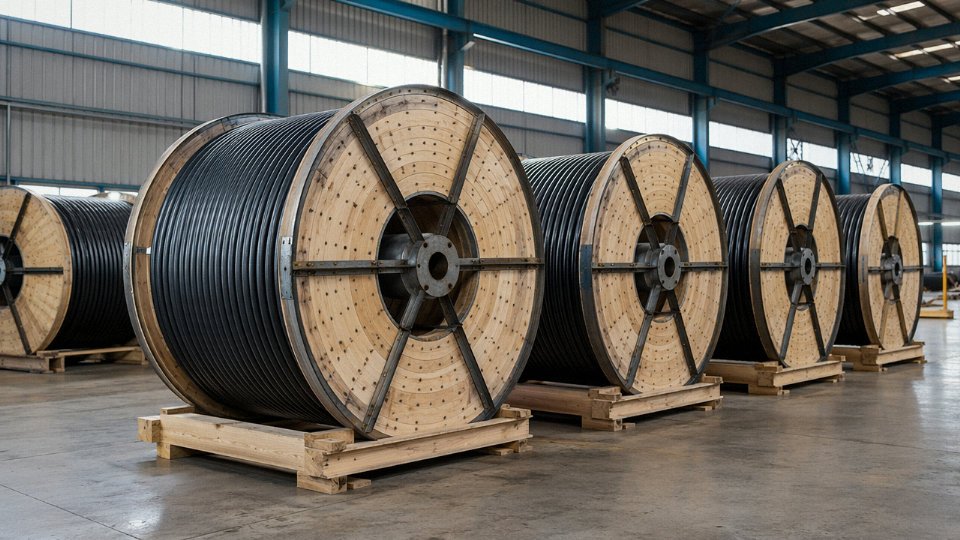
Five production bases across Shandong, covering roughly 470,000 m² of manufacturing floor, give Jinda the capacity to produce more than 50,000 km of SWA armored cable annually — enough to support large EPC procurement packages without the partial-shipment delays that plague smaller suppliers mid-project.
Export packaging uses wooden cable drums built to OIML-compliant standards, with drum diameters up to 3.5 m for long continuous lengths — relevant when your above-ground route requires minimum-joint runs or when jointing cost justifies paying for longer factory lengths. Sea freight goes out as both FCL and LCL depending on order volume. Standard export documentation includes electrical test reports (voltage withstand, insulation resistance, conductor resistance), material test certificates (MTC) for armor wire and conductor, and country-of-origin certificates for customs compliance.
Engaging Jinda’s Technical Team
Submit your project cable schedule — voltage rating, conductor size and material, core configuration, length per type, required sheath, and installation environment description — and Jinda’s application engineers will return a technical compliance statement confirming how each line item maps to the relevant IEC or project specification, plus an ex-works quotation. In practice that turnaround runs within five business days for straightforward schedules. For complex projects with derating queries, gland compatibility checks, or ITP requirements, the same team handles it — you’re not bounced between a sales desk and a technical department.