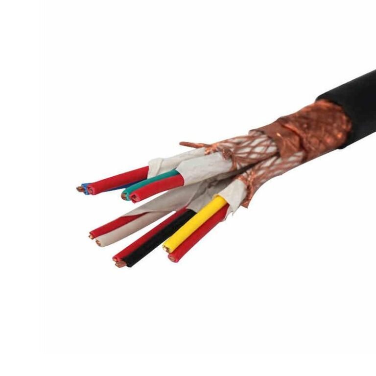
Specify the wrong cable type on a purchase order — wrong voltage rating, wrong insulation material, wrong armor class — and you may not find out until commissioning day, when a test failure shuts down the line or, worse, when an insulation breakdown causes a fault six months into production. Rework at that stage is expensive. Pulling and replacing buried or tray-mounted cable runs can cost five to ten times the original cable price once you factor labor, downtime, and schedule penalties. The problem is usually upstream: the sheer variety of cable constructions makes it genuinely difficult to map application requirements to the right product category, especially when a procurement manager is working from a spec sheet written by an engineer who assumed the plant-floor context was obvious.
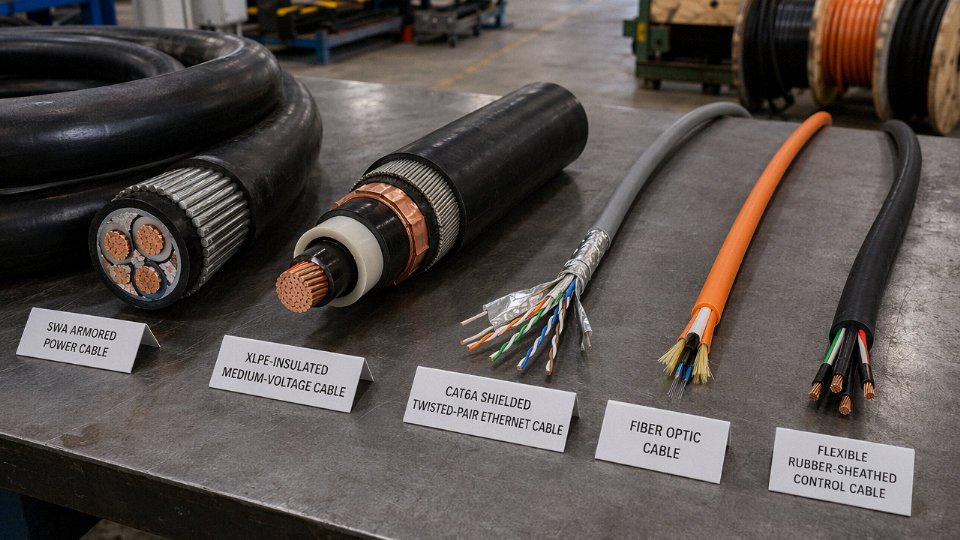
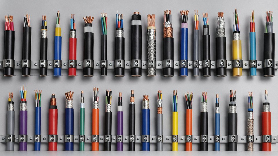
Cables are broadly categorized by function — power, control, instrumentation, data/signal, and specialty — and then further divided by voltage class, conductor material, insulation type, sheathing, and armor. Power cables run from 300/500 V for basic wiring up to 500 kV and beyond for transmission. Control and instrumentation cables typically operate below 1 kV but demand tighter shielding and insulation tolerances. Data cables are rated by frequency and attenuation rather than voltage. Specialty cables — fire-resistant, submarine, tray-rated, flexible robotic — are defined by the environment or duty cycle they survive.
What makes this genuinely complicated is that the same cable can carry several classification labels simultaneously: a cable might be low-voltage and armored and fire-resistant and halogen-free, and each of those attributes is non-trivial to specify correctly. The global cable market was sitting around USD 225 billion in 2023 and is tracking toward USD 300 billion or more by 2030 — that growth is being driven by grid expansion, offshore wind, EV infrastructure, and industrial automation, all of which are pulling demand for cable types that barely existed as standard catalog items fifteen years ago. Understanding the full landscape is less about memorizing product names and more about understanding which design attributes matter for which applications.
Power Cables by Voltage Class: Low, Medium, High, and Extra-High Voltage Explained
Voltage class is the first sorting question in any serious cable procurement — get it wrong and you’re either over-specified (money left on the table) or under-specified (insulation breakdown, arc faults, and a very bad day for everyone on site). The IEC framework divides power cables into tiers based on rated voltage Uo/U, and each tier maps to a distinct slice of electrical infrastructure.
The Four Tiers and What Grid Infrastructure They Actually Serve
Low Voltage (up to 1 kV, per IEC 60502-1) covers the last mile of every distribution system — building wiring, factory floors, commercial fit-outs, street lighting, and most motor feeder circuits. Cross-sections run from 1.5 mm² up to roughly 630 mm², and this is the tier where you’ll see the most volume in bulk procurement simply because every building and every machine needs it.
Medium Voltage (1–36 kV, IEC 60502-2) is the workhorse of industrial and urban distribution: ring-main units feeding industrial parks, wind turbine export cables, mining feeder circuits, and the 6–35 kV distribution networks that backbone secondary cities in most of Asia and Africa. Cross-sections typically range from 35 mm² to 630 mm², sometimes larger for cable-intensive substations.
High Voltage (36–150 kV, IEC 60840) handles transmission at the regional level — underground city transmission rings, offshore wind inter-array export circuits, and grid interconnectors where overhead line RoW (right-of-way) isn’t viable. A single HV underground circuit in an urban retrofit can cost more than the substation equipment it feeds, so overspecification here compounds fast.
Extra-High Voltage and Ultra-High Voltage (150–500 kV and above, IEC 62067) is bulk transmission territory: HVDC converter station links, long-distance underground grid reinforcement, and submarine interconnectors between countries. The installed cost of submarine cable in this class reaches USD 1–3 million per kilometer depending on water depth, route complexity, and armoring specification.
Layer by Layer: What’s Actually Inside a Power Cable
A high-voltage power cable is not just a fat wire with thick plastic around it. Each concentric layer has a specific electrochemical or mechanical function.
The conductor — stranded copper or aluminum — carries the current. Copper offers roughly 60% better conductivity by cross-section, but aluminum is about one-third the weight and cost per kg, which is why most EHV and many MV cables in price-sensitive markets default to aluminum. The trade-off is termination complexity; aluminum oxidizes and creeps under compression, demanding more care at jointing.
The conductor screen (semi-conducting layer) smooths the electric field around the conductor surface, eliminating stress concentrations that would otherwise erode insulation from the inside out. Skipping or damaging this layer during installation is one of the more common causes of premature MV cable failure in practice.
XLPE insulation has largely displaced paper-oil (PILC) construction in new installations above 6 kV. The comparison isn’t trivial:
| Parameter | XLPE | Paper-Oil (PILC) |
|---|---|---|
| Max conductor temp | 90°C continuous | 80°C continuous |
| Installation flexibility | Good; bends readily | Stiff; vertical runs need oil stop joints |
| Environmental risk | Thermoplastic waste at EOL | Oil leakage risk, soil contamination |
| Jointing skill requirement | Moderate (heat-shrink or cold-shrink) | High (skilled paper-lapping) |
| 40-year TCO | Lower in most scenarios | Higher maintenance, especially HV |
EPR (ethylene propylene rubber) insulation is worth calling out separately. It’s used where XLPE would be the default but flexibility and moisture resistance matter more — offshore platform feeder cables, mobile mining equipment, and some naval applications. Costlier than XLPE, rarely justifiable for static buried runs.
The insulation screen, metallic sheath (lead or copper tape), and armor follow. Steel Wire Armored (SWA) is the standard for direct burial where mechanical damage is the primary threat — cable trenches near construction zones, crossings under roads. Steel Tape Armored (STA) suits low-mechanical-stress environments, typically indoor or duct-run cables where you mainly need the electromagnetic shielding benefit. Aluminum Wire Armored (AWA) is specified for single-core AC cables where SWA would create a magnetic loop and cause unacceptable eddy-current heating — this matters a lot in large single-core HV circuits, and substituting SWA for AWA in those applications is a genuine design error.
Multi-Core vs. Single-Core in MV and HV Systems
Below 35 kV, three-core cables are common and often preferred: simpler jointing, one trench, one pulling operation. Above 35 kV, single-core construction dominates because manufacturing triple-layer insulation systems concentrically around three conductors at high voltage becomes impractical at large cross-sections.
Single-core HV cables are almost always laid in trefoil formation — equilateral triangle arrangement, cables touching or at a fixed spacing — because flat formation creates unequal impedance between phases and measurably reduces current-carrying capacity, typically by 5–12% depending on conductor size and laying depth. That derating matters when you’re sizing a circuit close to thermal limits.
Trefoil laying arrangement increases current-carrying capacity compared to flat formation for single-core HV cablesTrue
In flat formation, the center cable dissipates heat less efficiently than the outer two, creating unequal thermal loading. Trefoil formation balances mutual heating and typically allows 5–12% higher continuous current rating for the same conductor cross-section and burial depth, per IEC 60287 calculation methodology.
Voltage Class Reference Table
| Voltage Class | Typical Application | Insulation | Conductor Range | Key Standard |
|---|---|---|---|---|
| LV (≤1 kV) | Building wiring, motor feeders | PVC, XLPE | 1.5–630 mm² | IEC 60502-1 |
| MV (1–36 kV) | Industrial distribution, wind turbine cables | XLPE, EPR | 35–630 mm² | IEC 60502-2 |
| HV (36–150 kV) | Underground city networks, offshore export | XLPE | 95–2500 mm² | IEC 60840 |
| EHV (150–500 kV) | Bulk transmission, submarine interconnectors | XLPE | 630–2500 mm² | IEC 62067 |
Jinda manufactures across LV through HV ranges from its five production bases in China, with CE, ISO 9001, and CCC certifications covering the product range relevant to most international project compliance requirements. For EHV and HVDC submarine cable, the manufacturing and testing infrastructure requirements step up considerably — any serious procurement for that tier warrants detailed factory audit and type-test documentation review regardless of supplier.
Data and Communication Cables: Ethernet, Fiber Optic, Coaxial, and Telephone Cables
The physics of data transmission dictates everything — bandwidth ceiling, maximum run length, susceptibility to interference, and ultimately cost per installed meter. Choose the wrong medium and you’re either over-engineered and over-budget, or you’re watching a factory automation network drop packets every time a VFD cycles. Neither outcome is acceptable.
Twisted-Pair Ethernet: Category Ratings Actually Mean Something
Unshielded twisted pair is still the backbone of most building and campus networks, and the category designation is not just a marketing tier — it encodes conductor gauge, twist rate, insulation geometry, and maximum frequency, all of which determine real-world throughput.
| Category | Max Speed | Frequency | Max Distance | Shielding | Typical Use |
|---|---|---|---|---|---|
| Cat5e | 1 Gbps | 100 MHz | 100 m | Usually UTP | Office LAN, IP cameras |
| Cat6 | 1 Gbps (10G at 55 m) | 250 MHz | 100 m / 55 m at 10G | UTP or STP | Server rooms, denser office |
| Cat6A | 10 Gbps | 500 MHz | 100 m | F/UTP or S/FTP | Data centers, horizontal runs |
| Cat7 | 10 Gbps | 600 MHz | 100 m | S/FTP (pair + overall) | PoE++, future-proofed floors |
| Cat8 | 25–40 Gbps | 2,000 MHz | 30 m | S/FTP | Top-of-rack, switch-to-switch |
Cat8 looks impressive until you realize 30 m is barely enough for most data center rows, so it’s genuinely a top-of-rack play and nothing else. Cat6A is usually the right call for any new horizontal installation if you expect the cabling to last a decade — the cost delta over Cat6 is modest and the headroom is significant.
Fiber Optic: When Copper Runs Out of Distance or Isolation
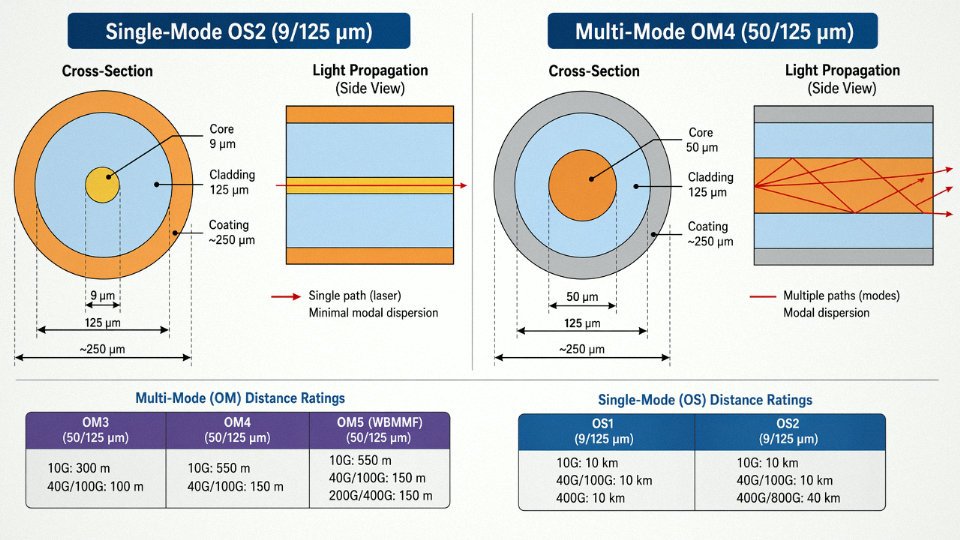
Fiber transmits light pulses rather than electrical signals, which means no electromagnetic interference pickup and no ground loop issues — both serious concerns in industrial plants with large motors nearby. Single-mode fiber (OS1/OS2, 9/125 µm core) uses a laser source and a narrow core to achieve distances exceeding 80 km on a single span, sometimes well beyond that with amplification. It dominates telecommunications backbone, campus inter-building links, and any run over roughly 300–400 m where you need guaranteed performance.
Multi-mode fiber (OM1 through OM5, 50/125 µm or 62.5/125 µm core) uses LED or VCSEL sources and suits shorter distances — OM3 handles 10 Gbps to about 300 m, OM4 to 400 m, and OM5 is rated for 400 Gbps over short wideband runs. In practice, OM3 or OM4 covers nearly every intra-building and intra-campus scenario cleanly.
Single-mode OS2 fiber can reliably transmit data over distances exceeding 80 km without active amplification in standard installationsTrue
OS2 single-mode fiber using standard SMF-28 compatible specifications supports spans of 80 km or more at wavelengths of 1310 nm and 1550 nm, which is well-documented in ITU-T G.652D and common telecom deployment practice.
Coaxial Cable: Obsolete in Theory, Indispensable in Practice
Coax — a center conductor, dielectric foam, braided shield, outer jacket — handles RF frequencies that twisted pair simply cannot. RG-6 remains the standard for CATV distribution and satellite feeds. RG-11 drops signal loss enough to justify its thicker, stiffer form factor on longer runs above roughly 60 m. RG-58 is thinner and more flexible, common in CCTV installations and short RF patch runs.
Fiber has taken most long-haul broadband away from coax, but hybrid fiber-coaxial (HFC) networks still pass millions of premises, and RF transmission for antenna feeds, radar systems, and broadcast equipment isn’t migrating to fiber anytime soon.
Installation Environment Ratings — Often the Deciding Factor
A cable’s rated performance means nothing if it’s destroyed by its installation environment. Plenum-rated cables (CMP per NEC, or meeting IEC 60332-3 equivalents) use low-smoke, flame-retardant jackets for air-handling spaces because burning standard PVC in a plenum spreads toxic smoke through an entire building. Riser-rated (CMR) cables are specified for vertical shaft runs between floors. Direct-burial variants add a gel-filled or armored construction that resists moisture ingress and ground movement. Outdoor-rated UV-stable jackets handle rooftop and aerial runs without cracking within a few seasons.
Getting this wrong isn’t just a code violation — a standard PVC jacket in a plenum cavity will fail the NFPA 70 inspection and trigger a costly rip-and-replace.
Industrial Ethernet and the Factory Floor Difference
Standard Cat6A pulled from a commercial spool will fail early in a machine cabinet. Industrial Ethernet cables — Cat6A industrial variants, PROFINET-compliant cables, EtherCAT-compatible assemblies — use TPE or PUR jackets that resist cutting oils, coolants, and cleaning solvents, plus flexible stranding that survives continuous flex cycles on cable carriers. Shielding on industrial Ethernet is also more robust, typically S/FTP, because the EMI environment near servo drives and frequency inverters is genuinely hostile. Specify the right cable upfront; swapping out a cable run inside a running production line costs far more than the price difference at procurement.
Hybrid Cables: One Pull, Multiple Functions
Smart building projects and 5G small-cell deployments increasingly use hybrid cables that combine optical fiber for data with copper conductors for low-voltage power in a single jacket. This cuts conduit fill, simplifies installation labor, and matters a lot in retrofit situations where pulling multiple separate cables through existing pathways is expensive or simply not feasible. The trend is accelerating as PoE power demands grow and distributed antenna systems multiply.
Traditional telephone cable — twisted copper pairs, often in large multi-pair counts — is largely legacy infrastructure now, still maintained in older facilities and kept for PSTN interconnects, but rarely specified new. Where voice is still needed over copper, Cat3 or better handles it without a second thought.
Control, Instrumentation, and Signal Cables: Keeping Industrial Processes Accurate and Safe
These cables don’t move megawatts. They move decisions — and in a refinery, a power station, or a continuous chemical process, a wrong decision costs more than any transformer failure.
Control, Instrumentation, and Signal: Three Distinct Jobs
The terms get used interchangeably on site, and that’s a problem. Control cables carry switching and command signals — motor start/stop, valve open/close, relay trip — typically at 300/500 V up to 600/1000 V, with conductors sized 0.75 mm² to 4 mm² depending on load. Instrumentation cables carry low-level analog or digital sensor signals, usually millivolt-range transmitter outputs or the industry-standard 4–20 mA current loop. Conductor cross-sections here are typically 0.5–1.5 mm², and the electrical characteristics matter far more than current-carrying capacity. Signal cables are somewhat protocol-specific — optimized for noise immunity at defined impedance and capacitance for fieldbus systems, thermocouples, or RTDs.
Substituting a control cable where an instrumentation cable belongs is not a minor deviation. The capacitance and shielding structure are fundamentally different, and you’ll be chasing ghost signals for weeks.
Shielding Hierarchy — and When Each Level Is Actually Mandatory
Instrumentation cables come in four shielding configurations, and the choice is not cosmetic.
Unshielded pairs are acceptable only in electrically quiet environments — basically nowhere near a VFD, a large motor, or any high-frequency switching equipment.
Individually shielded pairs (IS) wrap a foil shield around each pair separately. This is the minimum for multi-pair cables running in a shared tray in a DCS system. Each pair’s drain wire connects to instrument earth at one end only — break that single-point earthing rule and you’ve built an antenna.
Overall shielded (OS) adds a second shield around the entire cable bundle. Useful for rejecting external electromagnetic fields, but it does nothing to prevent crosstalk between pairs inside the cable.
Individually-plus-overall shielded (IOS) combines both. This is what SCADA and DCS engineers should specify for long cable runs, for any signal under 10 mV, and for anything running parallel to power cables for more than roughly 10–15 meters. Interference rejection in IOS cables under real plant conditions can reach 60–80 dB — meaningfully better than OS-only configurations — though the actual figure depends on earthing quality, tray arrangement, and cable spacing.
Thermocouple Extension and Compensating Cables
This is where I’ve seen the most expensive mistakes. A Type K thermocouple measures temperature based on the Seebeck effect at the junction between its nickel-chromium and nickel-aluminium alloys. Run that signal back to a transmitter through standard copper cable and you’ve introduced a second, uncontrolled thermoelectric junction — one that drifts with ambient temperature and introduces calibration errors that can reach several degrees Celsius, sometimes more.
Extension cables use the same alloy pairs as the thermocouple itself. Compensating cables use lower-cost alloys that approximate the thermoelectric output within a limited temperature range (typically up to 100–200°C ambient). Substituting copper is not a workaround. It is a calibration error that’s baked in.
Using standard copper cable instead of matched thermocouple extension cable introduces a parasitic thermoelectric junction that causes temperature measurement error.True
The Seebeck effect generates a voltage at any dissimilar-metal junction. If the cable alloy doesn't match the thermocouple type, an uncontrolled junction forms at the transition point, adding a temperature-dependent voltage offset to the signal — confirmed by IEC 60584 and standard calibration practice.
Type R, S, and B thermocouples use platinum-based alloys; their extension cables are significantly more expensive than Type K or J equivalents and occasionally get value-engineered out of a project. That’s a mistake. The measurement error compounds over the cable run and gets worse as the cable tray heats up seasonally.
Fire-Resistant and Circuit Integrity Cables
Emergency lighting, fire alarm loops, deluge valve control, emergency shutdown (ESD) circuits — all of these must keep working while the building around them is burning. Standard XLPE or PVC insulation fails somewhere between 150°C and 300°C. A fire-resistant cable rated to IEC 60331 or BS 6387 Category CWZ wraps the conductor in a mica tape layer under the primary insulation. Mica doesn’t melt; it forms a stable ceramic-like barrier that maintains electrical continuity at 750–950°C for 90–180 minutes, depending on the specific rating. The CWZ designation means the cable survives fire, water spray (as from sprinklers), and mechanical shock simultaneously — the realistic worst case in a real emergency.
Specify these cables for any circuit that must remain functional during an emergency, not as an upgrade option.
Fieldbus Cables: Impedance Is Not Negotiable
HART protocol rides on top of the standard 4–20 mA loop and is relatively forgiving. Foundation Fieldbus H1 and PROFIBUS PA are different — both use a defined bus topology at 31.25 kbit/s with specific requirements for characteristic impedance (typically 100 ± 20 Ω), cable capacitance (under roughly 200 nF per km for FF H1), and attenuation. Exceed the capacitance budget on a long segment and your devices drop off the bus intermittently — the sort of fault that appears random but is entirely predictable from the cable spec sheet.
Always verify the manufacturer’s segment length calculator against the actual cable’s published parameters. Cables marketed as “fieldbus compatible” vary considerably.
Hazardous Area Cables: ATEX and IECEx
For Zone 0, Zone 1, and Zone 2 classified areas under IECEx and ATEX, the cable itself must comply — not just the connected equipment. Intrinsically safe (IS) circuits in Zone 0 and Zone 1 applications require cables with defined maximum inductance and capacitance parameters that stay within the safety barriers’ rated limits. Use a cable with higher capacitance than specified and the stored energy budget is exceeded, removing the intrinsic safety guarantee entirely.
Cable jackets for hazardous areas are typically LSZH (low-smoke zero-halogen) or specialized fluoropolymer materials to resist hydrocarbons and H₂S environments common in upstream oil and gas.
Procurement Checklist for a Greenfield Petrochemical Project
| Parameter | Typical Requirement |
|---|---|
| Pair count | 2–24 pairs, project-specific |
| Conductor size | 0.5–1.5 mm² (or AWG 20–16) |
| Shielding | IOS as default; IS minimum for DCS analog |
| Jacket material | LSZH, PVC, or HDPE depending on area classification |
| Voltage rating | 300/500 V instrumentation, 600/1000 V control |
| Temperature range | –20°C to +90°C (–40°C for outdoor northern installations) |
| Flame/fire rating | IEC 60332-3, IEC 60331 where circuit integrity required |
| Standards | IEC 60502-1, ISA-5.1, IEC 61158 (fieldbus) |
| Hazardous area | IECEx/ATEX certification, IS parameters documented |
Get these parameters locked down in the material requisition before going to tender. Sourcing the wrong shielding configuration after cable trays are installed is a problem that no change order solves cheaply.
Specialty Industrial Cables: Mining, Shipbuilding, Railways, Wind Energy, and Oil and Gas
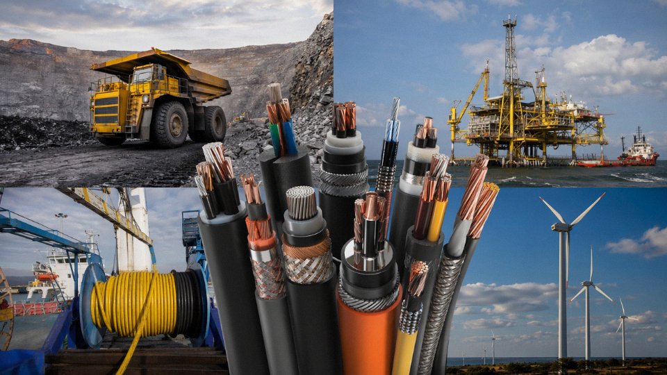
Standard commercial cable fails fast in extreme environments — not gradually, but catastrophically. A trailing cable dragged across a mine floor, a shipboard cable exposed to engine-room oil mist, a wind turbine cable twisting through 600° of nacelle rotation over two decades — these are environments where generic product selections become expensive downtime events. Specialty cables are engineered from the conductor outward for a specific punishment profile.
Mining Cables: Built for the Worst Floor You’ve Ever Seen
Trailing cables for continuous miners and shuttle cars take abuse that would destroy most cable within days. They’re dragged, crushed under wheels, kinked, and exposed to methane atmospheres simultaneously. EPR (ethylene propylene rubber) insulation handles the electrical stress and stays flexible at low temperatures — critical in underground conditions where ambient temps can swing widely. CPE (chlorinated polyethylene) jackets resist oil, flame, and abrasion in ways that PVC simply can’t match at the required wall thicknesses. Grounding conductors aren’t optional here; MSHA regulations (30 CFR Part 18 in the US) mandate specific grounding arrangements and ground-check conductors to ensure that a jacket breach triggers a protective relay before anyone gets hurt. Cables without current MSHA approval shouldn’t be on a mining site, full stop.
Marine and Shipboard Cables: Confined-Space Fire Logic
The fire risk calculus on a vessel is completely different from a land installation. When smoke fills an engine room or accommodation deck, you have minutes, not hours. This is why IEC 60092 series cables — the baseline for shipboard wiring — mandate LSZH (low-smoke zero-halogen) compounds for most interior runs. Halogens liberate toxic, corrosive gases when burned; on a ship, that’s lethal in confined spaces and destroys navigation electronics. Classification societies like DNV, Lloyd’s Register, and Bureau Veritas audit cable specifications as part of vessel certification, and they’re not lenient. Construction details matter too: mudguard sheaths, tinned copper conductors for corrosion resistance, and oil-resistant outer jackets for machinery spaces. Getting a substitution approved mid-build adds weeks to a commissioning schedule.
Railway Cables: Vibration, Flame, and Zero Halogen
EN 50264 governs rolling stock cables across European railways, and the requirements stack up: flame retardancy, low smoke density, halogen-free construction, and mechanical endurance under constant vibration. A cable clip-mounted to a bogie frame sees perhaps 10–15 million vibration cycles over a service life. Trackside signaling cables face a different threat — ground movement, rodents, and intermittent flooding — while traction power cables carry the high fault currents that make insulation integrity non-negotiable.
Wind Energy Cables: 20 Years of Continuous Torsion
Tower cables in a wind turbine rotate with the nacelle as it yaws to track wind direction — potentially up to 720° of cumulative twist before the cable management system unwinds. Over a 20-year turbine life, this is a continuous flex-fatigue test. IEC 60228 Class 6 fine-wire stranded conductors handle torsional stress without conductor breakage; polyurethane or rubber jackets maintain flexibility across the temperature range from -40°C winter lows to elevated nacelle temperatures. Submarine inter-array cables connecting turbines to offshore substations face their own engineering problem: burial in seabed sediment, dynamic bending at j-tube hang-off points, and voltage requirements that can reach 66 kV on modern arrays.
A single offshore wind farm may require 200–500 km of submarine and inter-array cables, with installed costs reaching USD 1–3 million per kilometer depending on water depth, burial method, and regional logistics.True
These figures reflect industry-reported ranges for offshore wind projects; actual costs vary significantly with site conditions, cable rating, and contractor pricing.
Oil and Gas: Downhole Is a Different Planet
ESP (electric submersible pump) cables operate at bottomhole temperatures that can exceed 230°C, pressures above 15,000 psi, and continuous immersion in crude oil and H₂S-laden fluids that would dissolve standard polymers within weeks. EPDM and polypropylene insulation grades rated for these conditions exist, but material selection depends on the specific well chemistry — H₂S concentration, aromatic hydrocarbon content, and produced-water salinity all affect swell and degradation rates. Lead alloy sheaths provide a traditional barrier against fluid ingress; corrugated stainless steel armor serves the same function on premium constructions where lead isn’t acceptable. This is a category where cutting procurement cost by 8% on the cable spec can cost six figures in workover expenses when the pump fails early.
Solar, Elevator, Robotics, and Submarine Transmission
PV cables under IEC 62930 (and the widely referenced TÜV 2 Pfg 1169 specification) are rated to 1500 V DC, double-insulated for touch safety, and UV-stabilized for 25+ years of outdoor exposure — ordinary building wire fails from UV embrittlement within a few seasons in direct sun. Elevator traveling cables must sustain millions of vertical flex cycles while carrying both power and control signals in the same sheath. Robotic arm cables face three-dimensional flex in tight bend radii, sometimes with simultaneous torsion; conductor stranding and jacket material selection here is almost a custom exercise per application. High-voltage submarine transmission cables — the sort that link islands to mainland grids or carry offshore wind power to shore — operate at up to 500 kV DC, with paper-oil or cross-linked polyethylene insulation, lead sheaths, wire armor, and serving layers that together can push cable diameter past 200 mm. These aren’t catalog items; they’re project-engineered.
Conductor Materials, Insulation Types, and Jacket Compounds: The Material Science Behind Cable Performance
Getting the voltage class right is only half the specification. Pick the wrong conductor alloy or insulation polymer, and you’re looking at premature failure, warranty disputes, or — in a worst case — a fire cause investigation. This section works through the material choices layer by layer.
Conductor Alloys: Conductivity, Weight, and Environment
Annealed copper remains the default for good reason. It offers the highest conductivity of any practical conductor material, conforms to IEC 60228 Class 1 through Class 6 stranding options, and — critically — it stays workable after repeated flexing. For most MV and HV power cable, Class 2 stranded copper is the standard. Drop to Class 1 solid conductor and you gain slightly better DC resistance but lose the ability to handle any appreciable bending radius without cracking. Specify Class 5 or Class 6 for continuous-flex applications: robotic cable tracks, crane trailing cables, wind turbine dynamic loops inside the tower.
Aluminum carries roughly 61% of copper’s conductivity by cross-section, but it’s about 30% lighter and noticeably cheaper per unit length. For overhead transmission and large-building feeders, the weight and cost advantage is real. AA-8000 series alloy largely resolved the old creep and cold-flow problems that plagued early aluminum building wire — provided the terminations use rated aluminum lugs, not copper lugs with “adapted” torque. That’s a maintenance habit worth enforcing. Copper-clad aluminum (CCA) is a compromise product: lower DC resistance than pure aluminum but not quite copper-grade, and the bonding interface becomes a weak point in environments with thermal cycling or moisture ingress. It gets specified a lot in cost-sensitive secondary distribution wiring; for any application with frequent load cycling or damp conduit runs, I’d steer toward one material or the other rather than the blend.
Tinned copper matters wherever oxidation at the conductor surface is a real concern — marine environments, rubber-insulated cables where sulfur migration from the compound can attack bare copper, and anything running above roughly 150°C continuously. Silver-plated copper steps in for aerospace wiring and high-frequency signal lines above that temperature band where tin starts to lose its protective effect.
Insulation Polymers: Temperature, Flexibility, and Electrical Performance
PVC is everywhere because it’s cheap, adequately flame retardant out of the box, and easy to process. Its practical ceiling is around 70°C conductor temperature, and below −15°C it becomes brittle enough to crack during installation — which matters if you’re pulling cable in an unheated plant in January. UV resistance is poor without added stabilizers, so unsheathed PVC in outdoor sun exposure is a short-term solution at best.
XLPE extends the continuous operating ceiling to 90°C and handles short-circuit temperatures up to around 250°C, which is why it dominates MV and HV power cable globally. The cross-linked structure gives it better dielectric properties and excellent resistance to water treeing when the compound is properly formulated — dry-cure XLPE versus steam-cure makes a measurable difference in long-term partial discharge performance for cables above 12 kV.
EPR (ethylene propylene rubber) matches XLPE on the 90°C continuous rating but stays genuinely flexible down to −50°C. For mining trailing cables and offshore deck cables that get coiled and uncoiled in cold weather, EPR is the right call even though it costs more. It also tolerates higher moisture environments without the same water-tree sensitivity concern.
For applications above 180°C — furnace wiring, proximity to casting equipment, emergency circuits that must survive a fire — silicone rubber handles up to roughly 180°C continuous and survives flame exposure better than most polymers. PTFE, FEP, and ETFE fluoropolymers push the ceiling to 200–260°C depending on the specific compound, and their chemical inertness makes them the default for instrumentation cables routed through aggressive chemical environments. MICC (mineral insulated copper-clad) cables take this to the extreme: magnesium oxide powder insulation inside a copper tube, rated to 1000°C, used for fire-rated emergency circuits in tunnels and large commercial buildings. They’re rigid, expensive, require specialist termination tools, and absolutely worth it for life-safety circuits.
Jacket and Sheath Compounds
The outer jacket is your first environmental barrier. PVC jackets are graded by compound hardness and oil resistance: ST1 and ST2 are general industrial grades; TM2 and TM6 are cold-climate formulations with lower brittle-point ratings. For applications with hydraulic oil, cutting fluids, or fuel contact, polyurethane (PUR) jacket is significantly better — harder to nick, resistant to swelling, and it bounces back from abrasion rather than scoring like PVC.
LSZH (low-smoke zero-halogen) compounds are mandatory in confined spaces, public transport systems, and data centers where PVC combustion gases would incapacitate occupants before the fire itself does serious damage. The relevant tests are IEC 60754 for halogen acid gas emission and IEC 61034 for smoke density. Worth knowing: early LSZH compounds were noticeably stiffer and had lower mechanical strength than PVC; modern formulations have closed most of that gap, but you’ll still see spec sheets where the cold-bend temperature is 5–10°C higher than an equivalent PVC jacket.
LSZH cables produce significantly less toxic smoke than PVC cables during combustionTrue
PVC insulation and jackets release hydrogen chloride gas when burned, which is toxic and corrosive. LSZH compounds are specifically formulated to restrict halogen content, verified by IEC 60754, and produce measurably lower smoke opacity, verified by IEC 61034 — both tested independently and required by standards including EN 50575 for building wire.
CPE and CSPE (Hypalon) jackets are the workhorses for mining and marine cable sheaths: oil-resistant, flame-retardant, UV-stable, and tolerant of ozone exposure that degrades standard rubbers over time. They cost more than PVC but considerably less than fluoropolymer options.
Armor and Metallic Sheaths
| Application Environment | Recommended Insulation | Recommended Jacket | Armor Type | Temperature Range |
|---|---|---|---|---|
| Indoor dry industrial | XLPE | PVC ST2 or LSZH | None or steel tape | −15°C to 90°C |
| Outdoor UV-exposed tray | XLPE | UV-stabilized PVC or LSZH | Galvanized steel wire | −20°C to 90°C |
| Direct burial, damp soil | XLPE | PE or PVC | Galvanized steel wire + oversheath | −20°C to 90°C |
| Chemical plant / acidic soil | XLPE | LSZH or PE | Stainless steel wire | −30°C to 90°C |
| Mining trailing cable | EPR | CPE or CSPE | None (flexible) | −40°C to 90°C |
| Marine / offshore deck | EPR | CSPE | Galvanized steel wire | −40°C to 90°C |
| Fire-rated emergency circuit | Silicone or MICC | LSZH (if polymeric) | None typical | Up to 1000°C (MICC) |
| Subsea / direct burial HV | XLPE | PE with lead or CAS sheath | Round steel wire | −20°C to 90°C |
Armor selection follows a simple corrosion-risk logic. Galvanized steel wire works for most buried and tray installations in neutral soils. Where soil resistivity is low and stray DC currents exist — near DC traction systems or cathodic protection zones — a lead alloy sheath or corrugated aluminum sheath (CAS) breaks the current path and prevents pitting corrosion of the armor wires underneath. Stainless steel wire armor is heavier and more expensive but worth the premium in chemical plant cable pits where galvanized wire would corrode within a few years. Aluminum wire armor is lighter than steel and suitable for single-core MV cables where a steel armor would generate eddy-current losses — a detail that gets overlooked on large cross-section cables and quietly inflates operating losses over a 25-year asset life.
International Standards, Certifications, and Compliance Marks That Govern Cable Procurement
Procurement engineers who have spent any time chasing a stalled project approval know the feeling: the cable arrived on site, the drums look right, the spec sheet looks right, and then the EPC contractor’s document controller kicks the submittal back because the test report came from an in-house lab rather than an accredited third party. Standards compliance is where cable procurement either moves forward or stalls for weeks.
The IEC Standards Family — What Each One Actually Tests
IEC standards are the baseline reference for most international projects outside North America. They are not interchangeable; each covers a distinct scope.
IEC 60228 defines conductor classes — Class 1 (solid), Class 2 (stranded), Class 5 and 6 (flexible) — along with dimensional and resistance requirements. Getting this wrong affects termination compatibility and current-carrying capacity calculations.
IEC 60332 is the flame propagation family. Part 1 covers a single vertical cable; Part 3 covers bundled cable installations in cable trays, which is the relevant test for most switchroom and tray-routed building wiring. The test category — 3A, 3B, 3C — affects how much non-metallic cable volume is permitted per meter of tray.
IEC 60502 governs extruded insulation power cables from 1 kV through 30 kV. Most LV and MV power cable procurement in the Middle East, Southeast Asia, and Africa references this standard. IEC 60840 picks up at 30 kV through 150 kV, with progressively more demanding partial discharge and impulse withstand tests. Cables above 150 kV fall under IEC 62067.
IEC 61156 covers balanced pair data cables — the standard behind Cat 6A, Cat 8, and similar structured cabling products. IEC 60092 governs marine and shipboard cables, specifying oil resistance, halogen-free requirements, and fire performance criteria that simply do not appear in land cable standards. IEC 62930 is the relatively newer photovoltaic cable standard, specifying UV resistance, thermal aging, and ozone resistance relevant to outdoor DC string wiring on solar installations.
Regional Marks and What They Actually Mean
CE marking on a cable sold into the EU under the Construction Products Regulation (CPR) is a Declaration of Conformity — the manufacturer’s statement, not independent certification. The CPR fire performance classes range from Eca (basic flame spread) up through Dca, Cca, Bca, and Aca, each reflecting progressively stricter flame, smoke, and droplet tests. Specifying the wrong CPR class for a public building project in Germany or France can trigger a full material replacement.
UL listing in North America operates differently. UL 44 covers thermoset-insulated cables, UL 83 thermoplastic-insulated, UL 1277 electrical power and control tray cable. A UL Listed cable has been tested to UL’s own standards, with ongoing factory follow-up inspections — not just a one-time submission. CSA certification covers Canadian requirements, and while UL and CSA often test to harmonized standards, project specs sometimes require both marks independently.
RoHS and REACH compliance restrict hazardous substances — lead, cadmium, certain phthalates — and increasingly appear as hard contractual requirements in EU public procurement and in supply chains serving European OEMs.
Type Approval, Routine Testing, and Sample Testing
These three IEC quality assurance tiers are frequently confused in submittals.
Type tests qualify a new cable design. They are destructive, extensive, and run once — unless the design changes materially. Think high-voltage impulse withstand, bending tests, and full thermal cycling sequences.
Routine tests happen on every production reel before shipment: conductor resistance, insulation spark test, voltage withstand. If your delivery skips routine testing, you have no per-reel quality evidence.
Sample tests fall between the two — periodic checks on production samples, covering things like insulation thickness measurement and tensile properties.
EPC contractor submittals for major infrastructure projects typically require type test reports dated within a defined period (often 5–7 years), plus routine test certificates for each shipped reel. Knowing which tier you are reviewing matters.
Third-Party Test Reports Versus Factory Self-Declaration
A CNAS-accredited laboratory test report carries independent weight. CNAS (China National Accreditation Service) accreditation means the lab’s methods and equipment have been independently audited against ISO/IEC 17025. An internal factory test certificate — even from a reputable manufacturer — is self-declaration. For domestic Chinese projects this is often acceptable. For international EPC projects, government tenders, or insured infrastructure, it usually is not.
Cables tested by CNAS-accredited or equivalent nationally accredited laboratories provide independent verification of compliance, whereas manufacturer-issued internal test certificates do not constitute third-party certification.True
CNAS accreditation is granted under ISO/IEC 17025 by China's national accreditation body, and CNAS-accredited test reports are recognized under international mutual recognition arrangements (ILAC MRA). Internal factory test certificates reflect the manufacturer's own measurements without independent audit of methods or equipment.
Reading a Cable Drum Label Before You Accept Delivery
A cable drum label should tell you the standard reference, conductor cross-section, insulation and jacket material codes, voltage rating, flame test class, reel number, gross and net length, and manufacturing date. The meter markings printed on the outer jacket sheath every 1–2 meters allow a quick field check that the reel length matches the label — a discrepancy of more than roughly 1–2% is worth querying before you sign the delivery note. Core color coding follows IEC 60446 in most international markets (green/yellow for protective earth, blue for neutral) or NEC conventions in North American projects; mixing the two on a single installation is an error that turns up at commissioning in the worst possible way.
How GB/T Standards Relate to Export Certification
China’s GB/T standards are in many cases harmonized with IEC, but not identical. Voltage designations, test sequences, and marking requirements can differ in ways that matter to import authorities. CCC (China Compulsory Certification) is the mandatory mark for cables sold within the Chinese domestic market; it has no standing in EU, North American, or Gulf Cooperation Council projects. Jinda’s export production lines are tested and certified to destination-country standards — IEC, UL, CPR, or others as specified — with third-party test reports from accredited laboratories included in documentation packages. For EPC submittals and international project audits, the documentation package typically includes type test reports, routine test certificates, material compliance declarations (RoHS, REACH), and ISO 9001 quality management system certification, assembled to match the contractor’s specific submittal template rather than a generic datasheet.
How to Specify and Source the Right Cable for Large-Scale International Projects
Getting the technical content right — voltage class, insulation type, armoring, conductor material — is only half the job. The other half is turning those technical decisions into a procurement process that actually delivers the correct cable to site, on time, in full, and with paperwork that satisfies the EPC contractor, the local electrical authority, and the project insurer. These two halves fail independently all the time. A cable schedule can be technically sound and still result in a compliance dispute that stalls commissioning for weeks.
Step 1: Define the Operating Environment Before You Touch a Datasheet
Start with the physical reality of where the cable will live, not with a vendor catalog. Voltage class and rated current are obvious starting points, but ambient temperature matters more than most engineers budget for — a cable that’s perfectly rated at 30°C may need to be derated by 15–25% if it’s running through a conduit bank in a Middle Eastern plant where ground temperature at burial depth sits above 40°C in summer. Installation method drives construction entirely: direct burial demands bedding and a mechanically robust armor (SWA or DSTA typically), while a cable tray environment shifts the priority toward flame retardancy and grouping derating.
Document hazardous area classification early. If the cable passes through or terminates in a Zone 1 or Zone 2 area (or NEC Class I Division 1/2 in North American specs), the gland selection, the cable OD tolerance, and sometimes the insulation compound all become constrained. Ignore this at specification stage and you’ll be buying replacement cable after the ATEX inspection.
Chemical exposure is frequently underestimated on process plant projects. Hydrocarbon splashing, H₂S atmospheres, and even prolonged UV exposure in outdoor cable trays can degrade a standard PVC outer jacket within a few years. Specify the jacket compound to the actual environment, not the generic project default.
Step 2: Nail the Standards Before Any Commercial Discussion
This step is where international projects get into trouble most often.
Specifying IEC cable construction but requiring UL certification on the same cable creates an unresolvable conflict because UL and IEC test protocols, conductor sizing conventions, and construction requirements are not directly equivalent.True
UL and IEC operate under different test methodologies and construction standards. A cable manufactured to IEC 60502-1 construction is not automatically testable to UL 1277, and conductor cross-sections in mm² do not map precisely to AWG sizes. Many project specification errors arise from copying clauses from different standard families without recognizing the incompatibilities.
Identify every stakeholder who will sign off on the cable: the project owner’s specification, the EPC contractor’s vendor list requirements, the local utility or electrical authority, and the insurance underwriter. Each may have a different mandatory standard. Reconcile conflicts before issuing the requisition — not during the factory acceptance test, which is where they usually surface.
Step 3: Build a Proper Cable Schedule
A cable schedule is a living engineering document, not an afterthought. For each circuit, calculate conductor cross-section using the current-carrying capacity tables in IEC 60364-5-52 (or the applicable national equivalent), then apply derating factors for grouping, burial depth, and ambient temperature. Running these corrections in sequence is important — apply them multiplicatively, not individually. Voltage drop verification is a separate check and sometimes governs the conductor size for long runs even when thermal capacity would allow a smaller cross-section. Short-circuit rating confirmation is often skipped on secondary circuits and comes back as a problem during arc-flash studies.
A compact reference for the main derating scenarios:
| Installation Condition | Typical Derating Factor Range | Key Variable |
|---|---|---|
| Cables grouped in tray (6–9 cables) | 0.70–0.78 | Number of loaded cables, spacing |
| Direct burial, soil temp 40°C | 0.87–0.93 | Reference temp assumption (usually 20°C) |
| Conduit in concrete slab, 3 circuits | 0.65–0.75 | Mutual heating, conduit fill |
| Ambient air 50°C (tropical outdoor) | 0.82–0.88 | Rated ambient vs. actual |
These ranges assume standard IEC reference conditions as the baseline. Your actual project values depend on soil resistivity, grouping geometry, and the base rating temperature written into your cable datasheet — so pull those numbers from the specific manufacturer’s data, not generic tables.
Step 4: Qualify the Supplier, Not Just the Sample
A test certificate for a sample reel means very little if the supplier can’t sustain that quality across 500 km of project cable on a 14-week schedule. Assess production capacity against your delivery window explicitly — ask for a production slot confirmation, not a generic lead-time claim. Review the ISO 9001 quality management system certificate and check its scope covers the specific cable types you’re buying. Third-party test reports should be recent (within 12–18 months is reasonable) and should cover the exact construction you’re ordering — not a similar cable with a slightly different core count or conductor cross-section.
Financial stability matters on projects with phased deliveries. A manufacturer that can’t secure copper rod at contracted prices mid-project creates schedule risk. Ask about raw material procurement practices and whether price-escalation clauses are needed for copper-intensive orders.
Step 5: Structure the Purchase Order to Survive International Logistics
Specify drum lengths explicitly. Standard 500 m or 1,000 m reels suit most projects and minimize joint locations; project-cut lengths reduce waste but can carry a lead-time premium of 2–4 weeks depending on the production queue. For sea freight, fumigated wooden drums with moisture-barrier wrapping are standard practice — and worth specifying contractually because undocumented timber packaging creates customs delays on arrival in many markets.
Incoterms selection has real operational consequences. CIF might look convenient, but it transfers risk at the port of destination without guaranteeing you have control over freight routing or insurance adequacy. Many experienced procurement managers on large cable orders prefer FOB with their own freight forwarder, particularly when cable drums are awkward to handle and damage claims are common.
Require factory acceptance testing (FAT) as a line item in the PO, with the right to witness or appoint a third-party inspector. Specify which tests are mandatory: conductor resistance, insulation resistance, high-voltage test, spark test for each reel, and dimensional checks. Post-delivery, request the full material test certificate package (MTC), the packing list reconciled against drum serial numbers, and the certificate of origin — these documents routinely become gatekeepers for project handover and insurance purposes.
Common Sourcing Pitfalls That Derail Projects
AWG-to-mm² substitution is probably the most frequent quiet mistake on international projects. A 4 AWG conductor is approximately 21.1 mm², not 25 mm². Specify mm² and check the drum labels and test certificates against your cable schedule — don’t assume a supplier interpreted the conversion your way.
Aluminum conductor substituted for copper is harder to catch if you’re not witnessing production or performing incoming inspection. The conductor resistance test on the FAT certificate will expose it, which is exactly why the FAT exists. Reduced stranding class is a similar issue: a Class 2 stranded conductor looks identical to a Class 5 flexible conductor on a reel end but behaves completely differently in a flexing application.
Non-armored cable shipped where SWA was specified is rarer with reputable suppliers but happens during shortages when substitutions are made without formal deviation requests. Build a contractual requirement for deviation approval into the PO terms, not just the technical specification.
Jinda’s pre-sales engineering team engages directly on specification review, including non-standard constructions where the project environment sits outside the catalog range — operating temperatures above 90°C continuous, double-armored submarine configurations, or halogen-free flame-retardant compounds qualified for specific shipboard approvals. Factory acceptance testing can be witnessed on-site at any of the five production bases, and the export documentation package — MTC, packing list, certificate of origin, and test records indexed by drum serial number — is prepared as a standard deliverable, not an optional extra.
Frequently Asked Questions About Cable Types, Selection, and Procurement
What is the difference between a cable and a wire?
Technically, a wire is a single conductor — either solid or stranded — with or without insulation. A cable is an assembly: two or more insulated conductors (or sometimes a single insulated conductor wrapped in a metallic sheath or armor) bound together under a common outer jacket. That’s the textbook answer. In practice, you’ll hear electricians and even engineers use “wire” to mean any insulated conductor, and nobody on the floor usually corrects them. It matters most in specifications and procurement documents — writing “wire” when you mean a multi-core armored assembly can create real ambiguity with a supplier quoting across three continents.
Can I use the same cable for AC and DC power systems?
Not reliably, and the consequences of getting this wrong can be severe. DC circuits produce no natural zero-crossing, which means any arc that develops during a fault or disconnection doesn’t extinguish the way it does in AC. At the 1000–1500 V DC levels common in utility-scale solar installations, standard AC-rated cables are genuinely undersized for the dielectric stress. DC-rated cables carry thicker insulation walls and specific dielectric withstand ratings tested under DC conditions. Always verify the cable’s DC voltage rating as a separate line item on the datasheet — don’t assume the AC rating covers it.
What does LSZH mean, and when is it actually required?
LSZH stands for Low-Smoke Zero-Halogen. When PVC burns, it releases hydrogen chloride gas — corrosive to lungs, lethal in enclosed spaces, and destructive to electronics. LSZH compounds are formulated to produce minimal smoke opacity and no halogenic acid gases during combustion. Specifying LSZH is mandatory in tunnels, passenger ships, data centers, airports, hospitals, and any application where emergency evacuation through a smoke-filled corridor is a real scenario. It’s also specified increasingly in data centers not primarily for human safety but because HCl vapor corrodes server hardware and copper buswork. The trade-off: LSZH jackets are generally stiffer and slightly less mechanically robust than PVC, which matters in applications with tight bend radii or repeated flexing.
LSZH cables produce no halogenic acid gases when burnedTrue
LSZH (Low-Smoke Zero-Halogen) compounds are specifically formulated to exclude halogen-containing materials such as chlorine and fluorine, verified under tests like IEC 60754-1 for halogen content and IEC 61034 for smoke density.
Copper or aluminum — how do I decide for a large power installation?
Copper’s conductivity runs around 58 MS/m versus roughly 35 MS/m for aluminum, which means an aluminum conductor needs a larger cross-section to carry the same current. That larger cross-section costs more in insulation and jacketing material, partially offsetting aluminum’s raw cost advantage. At cross-sections of 95 mm² and above in fixed installations — feeders, risers, substation interconnects — aluminum usually wins on total installed cost because the per-kilogram price gap is roughly 3–4×, depending on LME pricing at the time of procurement. The critical operational requirement: aluminum terminations must use AA-8000 series alloy conductors and purpose-rated compression lugs and connectors. Mixing aluminum conductors with fittings designed for copper is a common source of high-resistance joints and, eventually, fires.
SWA armored cable versus conduit-installed unarmored cable — which is right?
Steel Wire Armored (SWA) cable carries its mechanical protection with it. Direct burial, under roadways, through cable trenches across a large industrial site — SWA handles all of that without additional infrastructure. Unarmored cable in conduit relies entirely on the conduit for protection, which is perfectly valid in buildings and controlled indoor environments where conduit runs are already designed in. The practical decision point is usually installation cost: pulling conduit across a 600-meter outdoor run to an outbuilding costs significantly more in labor and materials than trenching in SWA directly, and SWA is also easier to re-route in future expansions.
How long should a quality power cable last?
XLPE-insulated cables are designed to a minimum 40-year service life under IEC standards, assuming installation and loading within rated parameters. That 40 years is not guaranteed under real-world conditions. Sustained overloading, repeated thermal cycling, water ingress at a poorly made joint, or a single poorly crimped termination can reduce actual service life drastically — in my experience, premature failures trace back to termination quality far more often than to the cable itself. Specified correctly and installed properly, XLPE power cable is genuinely long-lived infrastructure.
What lead times and minimum order quantities should I expect from an international cable manufacturer?
For standard LV power and control cables, a reputable manufacturer can often supply from 1 full drum — typically 500–1,000 meters — with lead times of a few weeks if the product is a standard catalog item. Custom specialty cables are a different situation. Mining trailing cables, offshore umbilicals, bespoke instrumentation cables with unusual shielding or armor configurations: expect minimum quantities in the range of 1,000–5,000 meters per type, with production lead times running 4–12 weeks depending on raw material availability and how deeply customized the design is. Lead times compress when the manufacturer runs an integrated supply chain — Jinda’s five production bases across China mean raw material sourcing, compounding, extrusion, and testing all happen within the same organization rather than waiting on outside suppliers. For time-sensitive projects, that vertical integration is worth asking about explicitly during supplier qualification.