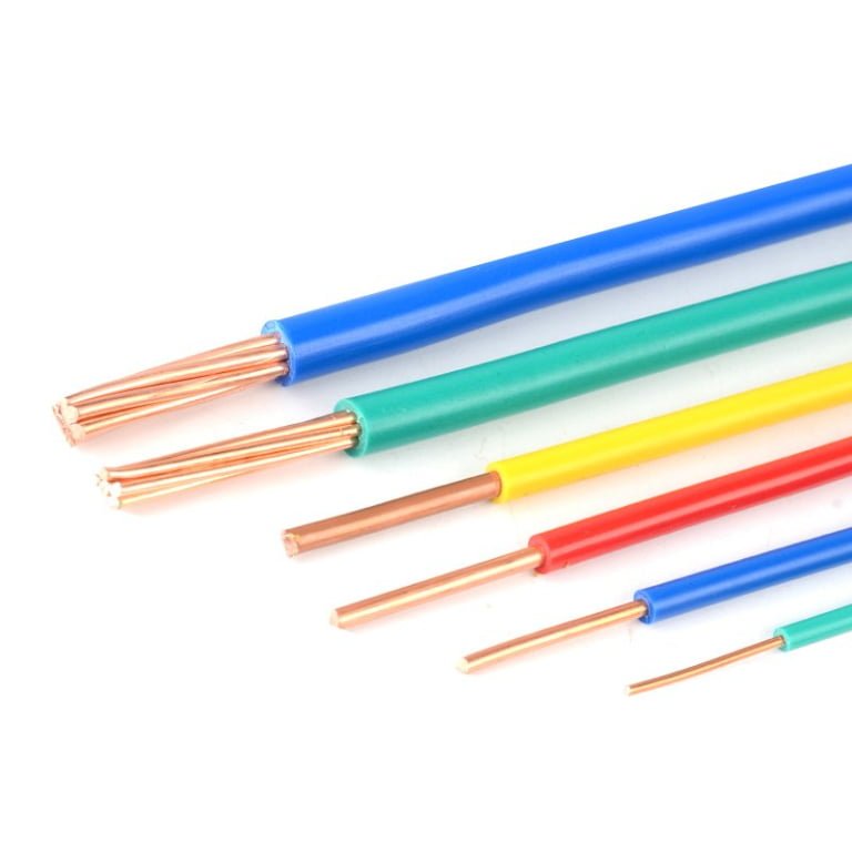
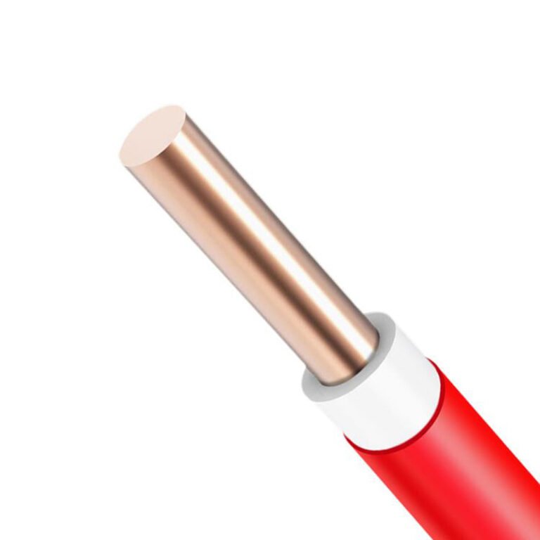
Pulling armored cable through conduit is one of those decisions that looks straightforward on the drawing but gets complicated fast on the floor. Get the fill calculation wrong and you’re re-pulling wire on day two. Spec the wrong conduit trade size and the armor’s corrugated jacket binds up mid-run, sometimes kinking or damaging the interlocked steel — which means scrapped cable, blown schedule, and a warranty argument nobody wants. The cost consequence isn’t just the rework labor; it’s the downstream delay on commissioning, especially on projects where the electrical rough-in is on the critical path.
Yes, you can install armored cable inside conduit, and in certain situations it is the correct approach — but it is not the default. NEC Article 330 permits MC cable in raceway systems, including EMT and rigid conduit. The catch is conduit fill: NEC Article 358 limits interior cross-section use to 53% for one cable, 31% for two, and 40% for three or more. Because armored cable outer diameters run from roughly 0.5 in (13 mm) on a small 14 AWG two-conductor up to 2.5 in (64 mm) or beyond on large feeder cables, trade size selection is critical and non-obvious.
What most installation guides skip is the practical gap between code compliance and actual field performance — pulling friction, conduit body radius limits, armor jacket behavior under tension, and the labor math that makes this combination genuinely expensive if not planned correctly. Those details are what determine whether the conduit-over-armor approach solves your problem or creates a new one.
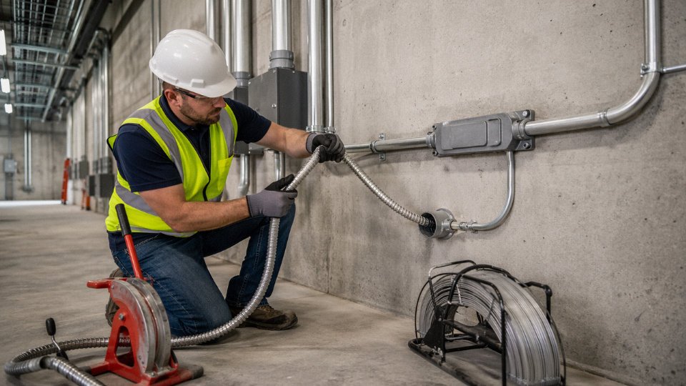
Code and Standards Framework: What NEC, IEC, and Global Regulations Actually Permit
The short answer is yes — but “permitted” and “practical” are two different things, and the standards landscape is messier than most quick-reference guides let on.
NEC Article 330: MC Cable in Conduit
Section 330.10(A)(5) of the National Electrical Code states explicitly that Type MC cable is a permitted wiring method when installed in cable trays, raceways, or other approved means. “Raceways” includes conduit — EMT, rigid metal conduit (RMC), intermediate metal conduit (IMC), and PVC Schedule 40 or 80 all qualify. The code does not restrict this based on conduit material, and it does not require you to strip the armor before pulling. What it does require is that you still comply with the fill calculations under Article 358 (for EMT) or the applicable raceway article: one cable at 53% of interior cross-section, two at 31%, three or more at 40%.
That last point trips people up more than the permission itself. A 1-inch EMT has an interior area of roughly 0.864 in². A 12 AWG three-conductor MC cable with aluminum interlocked armor typically runs about 0.56 in² in cross-section — already 65% fill if you try to pull just one. You’d need to step up to 1¼-inch trade size. Do the math before ordering conduit.
NEC Article 330.10(A)(5) explicitly permits Type MC cable to be installed inside conduit racewaysTrue
Section 330.10(A)(5) lists raceways as an approved installation method for Type MC cable, and the NEC defines raceways to include conduit types such as EMT, RMC, and IMC under Article 100.
Article 320: AC Cable Is a Different Animal
Type AC cable — the older BX-style product with a spiral steel armor and a bonding strip — falls under Article 320, not 330. The distinction matters because AC cable’s armor itself serves as the equipment grounding conductor path (via that internal aluminum bonding strip riding against the steel). Section 320.10 also lists raceways as a permitted installation method, so AC cable in conduit is technically allowed. But some AHJs get uncomfortable with it because the armor’s grounding continuity depends on mechanical contact quality, and pulling AC cable through a tight conduit bend can distort that armor in ways that degrade the bond. In practice, most engineers specify MC when conduit routing is planned from the start — cleaner armor, defined grounding conductors, fewer inspection arguments.
IEC 60502 and IEC 61386: The European Logic
IEC 60502 covers power cables with extruded insulation up to 30 kV, including armored variants (SWA — steel wire armored, and STA — steel tape armored). IEC 61386 governs conduit systems for cable management. Under IEC logic, armored cable already provides a defined mechanical protection class. Routing it inside conduit is not prohibited, but the framework describes this as “additional mechanical protection” rather than a required double barrier. The practical upside recognized in European project specs is that conduit offers chemical and UV protection where the cable’s armor does not — underground duct crossings, chemical plant trenches, areas with aggressive wash-down.
BS 7671 and UK Industrial Practice
Under BS 7671 (the IET Wiring Regulations, 18th Edition), SWA cable inside conduit appears regularly in offshore platform designs and petrochemical facilities. The driver is usually zone classification rather than structural need: IEC Zone 1 and Zone 2 hazardous areas sometimes require both the cable’s inherent armor and an additional raceway to satisfy the installation method requirements of the area classification documentation. Topsides cable routing on North Sea platforms, for example, routinely combines SWA cable inside galvanized steel conduit specifically because the platform operator’s own engineering standard calls for it, layered on top of whatever BS 7671 permits.
AHJ Variability: Get It in Writing
This is the piece most installation guides skip. The NEC and IEC documents set floors, not ceilings. Local Authorities Having Jurisdiction can and do impose stricter requirements. Healthcare facilities (NFPA 99 environments), Class I Division 1 hazardous locations, and Tier III/IV data centers are the three occupancy types where I’ve seen AHJs most frequently mandate armored cable inside conduit as a condition of their own facility standard — regardless of what the base NEC would allow on its own. If you’re designing for one of these occupancies, request a formal written interpretation from the AHJ before finalizing the installation drawings. Email leaves a record; a verbal conversation at a pre-construction meeting does not.
Standards Summary
| Standards Body | Relevant Article / Clause | Armored Cable in Conduit Permitted? | Key Restrictions |
|---|---|---|---|
| NEC (NFPA 70) | Article 330.10(A)(5) — MC Cable | Yes | Conduit fill limits per applicable raceway article; armor intact |
| NEC (NFPA 70) | Article 320.10 — AC Cable | Yes, with caution | Armor grounding integrity must be maintained; AHJ discretion common |
| IEC 60502 / IEC 61386 | Cable and conduit system standards | Yes — treated as additional protection | No explicit prohibition; design must address fill and bend radius |
| BS 7671 (IET 18th Ed.) | Chapter 52, Section 521 | Yes | Commonly required in hazardous area zone classifications and offshore specs |
| Local AHJ | Varies by jurisdiction | May be required (not just permitted) | Get written interpretation for healthcare, hazardous locations, data centers |
Engineering Rationale: Six Scenarios Where Installing Armored Cable Inside Conduit Is the Right Call
The combination looks redundant on paper. Two protective systems stacked on top of each other, each one theoretically sufficient on its own. In practice, there are at least six situations where pulling armored cable through conduit is not belt-and-suspenders overkill — it’s the only defensible design choice.
Hazardous (Classified) Locations Under NEC Article 501
Class I, Division 1 areas — think pump rooms, paint spray booths, compressor buildings with continuous flammable vapor presence — require explosion-proof wiring methods. NEC Article 501 permits Type MC-HL (metal-clad, hazardous location) cable, but in Division 1 spaces the cable must typically be installed in rigid metal conduit (RMC) or intermediate metal conduit (IMC) to maintain the explosion-proof assembly integrity at terminations. The armor alone does not provide the gas-tight, pressure-containing pathway that RMC fittings and seal-offs create. Skip the conduit in a Division 1 space and your entire wiring method is non-compliant, regardless of how robust the armor looks.
In NEC Class I, Division 1 locations, MC-HL cable alone without RMC or IMC conduit does not satisfy explosion-proof wiring method requirements under Article 501.True
NEC Article 501.10(A) specifies permitted wiring methods for Class I, Division 1 areas; the explosion-proof integrity depends on the conduit sealing fittings, not solely on the cable armor.
Underground Duct Bank Installations
PVC Schedule 40 or 80 conduit in a direct-buried duct bank protects against soil loading and the kind of slow ground movement that eventually crushes unprotected cable. But PVC joints leak — anyone who has pulled a flooded duct bank knows this. Running SWA or interlocked armored cable inside that conduit gives you a second line of defense: the armor handles mechanical damage if a joint fails or a rodent chews through at a coupling, and the conduit handles the compressive ground forces the armor was never rated to resist alone. In duct banks deeper than roughly 30 inches in active industrial yards, I’d call the combination essentially standard practice.
Seismic Zone 3 and 4 Critical Facilities
IBC and ASCE 7 seismic bracing requirements for hospitals, data centers, and nuclear facilities effectively force this combination for critical circuits. Seismic bracing hardware is designed around rigid metallic conduit systems. Armored cable in tray is difficult to brace to IBC Chapter 13 tolerances without the conduit providing the structural spine. The armor keeps the circuit alive if the conduit cracks or shifts at a coupling during a seismic event — conduit provides the bracing geometry, armor provides the post-event circuit continuity.
High-EMI Industrial Environments
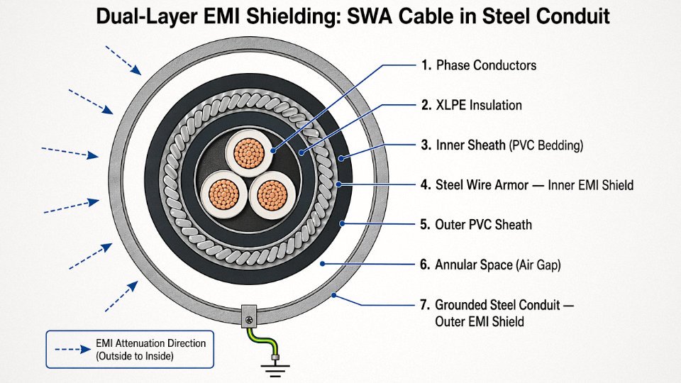
Steel mills and petroleum refineries generate electromagnetic interference that will corrupt 4–20 mA instrumentation signals and PROFIBUS runs through single-shield instrumentation cable. Using steel wire armored (SWA) cable inside a grounded steel conduit creates a two-layer shield: the conduit handles gross EMI, and the cable’s own armor and drain wire handle residual interference closer to the conductor. The combination typically reduces measured noise coupling by a meaningful margin compared to either system alone — actual attenuation depends on frequency, bonding quality, and conduit material, but the principle is sound and regularly specified in refinery I&C standards.
Transition Points from Open Tray to Enclosed Conduit
This one comes up constantly in industrial plant layouts. Armored cable runs through a cable tray across a bay ceiling, then drops into a conduit sleeve through a firewall or panel enclosure penetration. The armor handles the tray segment; the conduit handles the penetration. Trying to transition to unarmored cable at that junction just adds a splice and a potential failure point. Keeping the armored cable continuous through the conduit sleeve is cleaner and more reliable.
Corrosive and High-Moisture Environments
Wastewater treatment plants and marine installations expose conduit systems to hydrogen sulfide, chloramines, salt spray, and constant condensation cycles. PVC conduit handles the chemistry well but joints and fittings eventually admit moisture. Running armored cable — particularly cables with a PVC oversheath over the armor — inside that conduit means a conduit joint failure doesn’t immediately compromise the circuit. The armor buys time. In practice, the combination extends maintenance intervals and reduces the consequences of the conduit degradation that will happen eventually in a coastal or below-grade wet environment.
Conduit Fill Calculations for Armored Cable: Step-by-Step Sizing Method with Worked Examples
Getting the fill calculation wrong is one of the most common — and most expensive — mistakes on armored cable projects. Pull a conduit that’s 15% overfilled and you’re looking at damaged armor, stripped insulation at the bends, and a potential rejection from the AHJ inspector. Do it right the first time and the calculation takes maybe ten minutes.
Why Armored Cable Uses Overall OD, Not Conductor Area
NEC Chapter 9, Table 1 sets the fill limits most electricians can quote from memory: 53% for a single cable, 31% for two cables, 40% for three or more. What trips up even experienced engineers is which dimension to use for armored cable.
Standard conductor fill tables — Chapter 9, Table 5 — give you the cross-sectional area of the insulated conductor itself. That number is useless here. An MC or SWA armored cable has interlocked steel or aluminum armor, a jacket, filler material, and sometimes a ground wire outside the insulation bundle. The overall cable OD is considerably larger than what Table 5 shows, and that full outer diameter is what physically occupies space inside the conduit. Using Table 5 for an armored cable systematically underestimates the space consumed, sometimes by 40–60% on larger cables.
For armored cables, NEC fill calculations must use the cable's overall outside diameter (OD), not the individual conductor cross-sectional areas from Chapter 9 Table 5.True
NEC Chapter 9, Note 9 to Tables specifies that where cables are installed in conduit, the overall cross-sectional area of the cable including armor and jacket is used for fill calculations. Table 5 reflects insulated conductor dimensions only, which do not account for armor, jacket, or fillers.
Always pull the OD from the manufacturer’s datasheet — not a catalog estimate. For reference, Jinda MC-style armored cables run roughly 0.47–0.51 in (12–13 mm) OD on a 12 AWG 3-conductor build, around 0.72–0.78 in (18–20 mm) on 6 AWG 3-conductor, and approximately 1.20–1.32 in (30–34 mm) on a 2/0 AWG 3-conductor cable. These vary with armor type, jacket wall, and whether a ground conductor is included — confirm your specific part number.
Step-by-Step Procedure
Step 1 — Get the OD. Pull the actual datasheet. Write down OD in inches (or convert from mm: divide by 25.4).
Step 2 — Calculate cable cross-sectional area. Use A = π(OD/2)². A 12 AWG 3C cable at 0.49 in OD: A = π × (0.245)² ≈ 0.189 in². A 2/0 AWG 3C at 1.26 in OD: A = π × (0.63)² ≈ 1.247 in².
Step 3 — Compare to Table 4 allowable fill. NEC Chapter 9, Table 4 lists the interior cross-sectional area for each conduit trade size and type. For 1-inch EMT, total interior area is 0.864 in²; the 40% fill limit for three-or-more conductors gives you 0.346 in² allowable. For 3-inch Schedule 40 PVC, interior area is 7.073 in²; at 53% (single cable), allowable fill is 3.749 in².
Worked Example A: Three 12 AWG 3-Conductor MC Cables in 1-Inch EMT
Three cables, each at 0.189 in². Total fill = 3 × 0.189 = 0.567 in². Allowable in 1-inch EMT at 40% = 0.346 in².
Result: Fail. You’re at roughly 66% fill — well over the limit. Step up to 1½-inch EMT (interior area 1.610 in², 40% allowable = 0.644 in²). Now 0.567 ÷ 1.610 = 35%. Pass, with reasonable pulling headroom.
Worked Example B: One 2/0 AWG 3-Conductor SWA Cable in 3-Inch Rigid PVC
Single cable: 53% fill limit applies. Cable area = 1.247 in². 3-inch Schedule 40 PVC allowable at 53% = 3.749 in².
Result: Pass. Fill ratio = 1.247 ÷ 7.073 = 17.6%. Mathematically, a 2-inch conduit (interior area 3.291 in², 53% = 1.744 in²) would also pass at 38% — but in practice, for an underground duct bank with SWA cable, I’d stay with the 3-inch. Pulling tension on a rigid armored cable through a buried run with bends gets ugly fast, and you’ll thank yourself during the pull.
The One-Trade-Size Rule
Run the fill calculation, then upsize by one trade size anyway. This is not in the NEC — it’s operational experience. Armored cable is stiffer than THHN. It doesn’t coil tight at bends. Pulling tension climbs sharply past two 90° sweeps, and overfilled conduit concentrates that tension on the armor at the conduit entry. The labor cost differential for the larger conduit pipe is minor compared to the risk of a damaged cable or a blown pull on a long underground run.
Pulling Tension, Bend Radius, and Physical Installation Limits for Armored Cable in Conduit
The fill calculation tells you whether the cable fits on paper. What it doesn’t tell you is whether you can actually get it through without damaging it — and that’s where a lot of conduit installations with armored cable go wrong.
Bend Radius: The Constraint That Surprises Most Installers
THHN singles are flexible enough that a standard 5× OD minimum bend radius rarely causes problems in typical conduit runs. Armored cable is a different animal. The interlocked aluminum armor or galvanized steel wire braid adds rigidity that resists tight bending, and the minimum bend radius climbs to somewhere between 7× and 12× the cable’s overall OD depending on armor type, conductor count, and the specific manufacturer’s spec. For a 1-inch OD MC cable, that’s a minimum bend of roughly 7 to 12 inches — which sounds manageable until you realize a standard 1-inch EMT sweep elbow has an inside radius around 8 inches. You may be right at the limit, or past it, before you’ve accounted for the actual pull angle.
This means every conduit body, elbow, and offset in the routing needs to be re-evaluated against the armored cable’s published bend radius, not the conduit’s rated radius. Standard LB conduit bodies are almost always too tight for anything beyond small-diameter armored cable. Sweep elbows with a 36-inch radius (or larger for cables above roughly 1.5-inch OD) are the right choice on larger feeders. It’s one of those things that looks fine on the drawing and turns into a field problem at 7 a.m.
Pulling Tension and What the Armor Weight Actually Does to It
The basic tension formula for a straight horizontal conduit run is T = μ × W × L, where μ is the coefficient of friction (typically 0.35–0.5 for lubricated pulls), W is the cable weight per foot, and L is the run length. Armor adds real mass — typically 15–40% more than the non-armored equivalent, depending on whether you’re dealing with aluminum interlocked armor or heavier galvanized steel wire armor. On a 200-foot run, that weight increase translates directly into higher pulling tension, and it compounds fast when you add vertical rise or multiple bends.
Most cable manufacturers publish a maximum allowable pulling tension (usually based on conductor cross-section), and it’s worth checking that number before the pull rather than after the jacket has stretched.
Sidewall Bearing Pressure at Bends
Sidewall bearing pressure — SWBP — is the force the cable exerts against the conduit wall on the outside of a bend. IEEE 1185 guidance pegs the general limit at 300 lb/ft of bend radius for most power cables, though some armored constructions have lower thresholds. The armored cable’s stiffer construction means it transfers more of the pulling tension into radial force at bends instead of flexing through them. On a run with multiple 90-degree bends and significant cable weight, SWBP can become the binding constraint well before you hit the tension limit.
Sidewall bearing pressure limits can be exceeded even when pulling tension is within spec, particularly on heavy armored cables pulled through tight-radius elbows.True
SWBP is a function of tension divided by bend radius. A cable pulled with moderate tension through a very tight elbow can exceed 300 lb/ft even if total pull tension looks acceptable, causing armor deformation or conductor damage.
Conduit Layout Rules That Actually Hold Up in the Field
Keep bends between pull points to two 90-degree equivalents maximum. Beyond that, friction and SWBP accumulate to a point where either the cable or the armor is taking damage even if the pull completes. Pull boxes at intervals no greater than 100 feet on heavy armored runs — closer if there are multiple bends in that stretch. It’s extra material cost up front, but compared to a damaged 4/0 armored feeder that has to come out and be replaced, it’s cheap insurance.
Lubrication Compatibility — Don’t Skip This Step
Pulling lubricant is mandatory on any conduit run with armored cable; friction alone will prevent completion of longer pulls or cause armor deformation. But the lubricant chemistry has to match both the armor material and the outer jacket. Petroleum-based pulling compounds can attack PVC and some thermoplastic-elastomer jackets over time, causing swelling or surface crazing that traps moisture later. Water-based gels are generally safer across jacket types. For aluminum interlocked armor specifically, avoid lubricants with chloride-containing additives — they accelerate galvanic pitting under the armor. Galvanized steel wire armor is more forgiving, but still deserves a compatibility check against the jacket spec sheet before ordering lubricant by the bucket.
In practice, the wrong lubricant is one of those failures that shows up months later as insulation resistance drift, not immediately as a failed pull — which makes it easy to miss the root cause.
How Manufacturing Quality Affects Pull-In Survivability
Armored cable that’s been manufactured with tight inter-layer dimensional control survives conduit pulls better than product where armor pitch or lay length is inconsistent. At Jinda, armored cables undergo inter-layer slip testing and armor crush resistance verification as part of the production QC protocol — specifically to confirm that the armor can handle the radial and axial forces imposed during conduit installation without the interlocked segments riding over each other or collapsing inward onto the conductors. For project procurement managers, it’s worth asking any armored cable supplier for their pull-in force test data, not just the finished product dimensional report. The difference between a cable that pulls cleanly through 150 feet of conduit with two sweeps and one that jams or deforms at the first elbow often comes down to manufacturing consistency, not installation technique.
Grounding, Bonding, and EMI Continuity When Armor and Conduit Are Both Present
Two metallic protection systems in the same installation means two potential grounding paths — and that’s where a lot of field wiring problems originate. Get it right and you have redundant fault-current capacity with clean EMC performance. Get it wrong and you’re chasing ground loops on a 4–20 mA loop at 2 a.m. wondering why your PLC is reading noise.
NEC 250.118 and the Hierarchy of Metallic EGCs
NEC 250.118 lists approved equipment grounding conductors, and both steel or aluminum MC cable armor and metallic raceway systems (EMT, rigid conduit, IMC) appear independently on that list. Each qualifies on its own. When you install armored cable inside metallic conduit, you haven’t created a superior ground — you’ve created two parallel EGC paths, and the code doesn’t automatically sort out which one carries fault current. In a properly installed system, both paths are bonded continuously, both carry fault current during a line-to-ground fault, and the fault clears faster because impedance is lower. For a 480 V power feeder, that’s usually fine. Nobody on the maintenance crew is losing sleep over it.
The complication arises on instrumentation and signal circuits. If the armor is bonded at both the panel end and the field device end, and the conduit is independently bonded at both ends to a separate ground bus, you’ve built a closed loop. Any varying magnetic flux threading that loop — from nearby VFD cables, from 60 Hz power conductors running parallel — induces a circulating current. On a thermocouple input or a 4–20 mA transmitter, that induced voltage can easily exceed the signal amplitude. I’ve seen this show up as a slow, rhythmic oscillation on a PID loop that the controls engineer initially blamed on tuning.
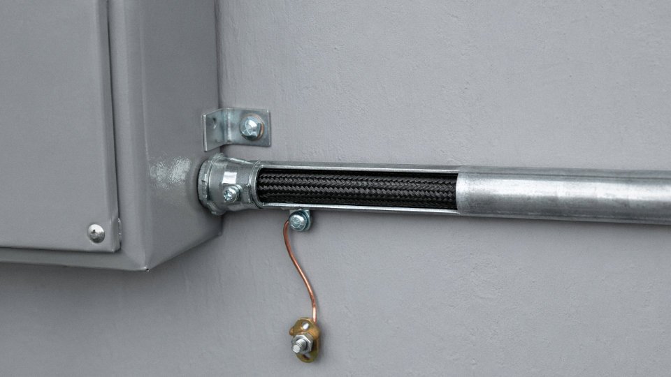
Practical Bonding Strategy
The cleanest solution: bond the armor to the conduit at the point of entry — one listed connector, one connection, both metallic systems electrically joined at that point and then grounded together through the conduit system to the panel ground bus. Don’t run the armor’s bonding conductor to a separate grounding terminal strip elsewhere in the panel. That separate connection is what creates the loop geometry.
Bonding MC cable armor independently to a separate ground bus while the conduit is also grounded creates a closed conductive loop that can induce circulating currents in sensitive instrumentation circuits.True
When two conductive paths form a closed loop and time-varying magnetic flux passes through that loop (from adjacent power conductors or VFDs), Faraday's law dictates an induced EMF proportional to the rate of flux change. This is a well-documented source of noise on analog instrumentation circuits in industrial plants.
IEC 60364-5-54 in European Industrial Plants
European installations follow IEC 60364-5-54, which addresses grounding and equipotential bonding for installations using armored cable in metallic conduit. The standard doesn’t prescribe a single bonding topology, but it does require that all exposed metallic parts be part of a continuous protective equipotential system. In TN-S systems — common in modern European industrial plants — the PE conductor is separate from neutral throughout, which makes it easier to keep armor and conduit bonding clean because you’re not fighting combined N-PE impedance at the source end.
Shielded Instrumentation Cable: The Triple-Layer Decision
Shielded instrumentation cable with armor inside metallic conduit gives you three conductive layers: the drain wire/foil shield, the armor, and the conduit wall. Each one needs a deliberate grounding decision.
For low-frequency interference (50/60 Hz, up to a few kilohertz), single-point grounding of the shield at the control panel end is standard practice — it prevents the shield itself from becoming a current-carrying loop. The armor should be bonded to conduit at entry, as described above. The conduit is grounded continuously through the raceway system.
For high-frequency EMI environments — near VFDs, near RF sources, in facilities with significant switching transient activity — multi-point grounding of the shield at intervals of roughly one-tenth of the interference wavelength becomes necessary. At 100 kHz that’s around 300 m; at 1 MHz it’s about 30 m. In practice most industrial plants deal with VFD switching frequencies in the 2–16 kHz range, so single-point shield grounding usually holds unless the cable run is very long or the analog signal is particularly sensitive.
Termination Hardware and Field Compliance
Proper bonding starts with the right connector at the armor termination point. Jinda’s factory-fitted armor termination connectors are designed to make simultaneous electrical contact with the armor and the conduit hub during installation, eliminating the need to add a separate bonding jumper in the field. Specifying the termination hardware alongside the cable — not as an afterthought sourced from a different supplier — ensures that the bonding impedance meets code requirements and that the installer doesn’t improvise something that looks correct but fails continuity testing six months later during a plant audit.
Cost-Benefit Analysis: When the Combined System Saves Money and When It Does Not
The honest answer is that armored cable inside conduit is sometimes the smartest specification on a project — and sometimes it’s just two engineers defaulting to belt-and-suspenders without running the numbers. Procurement managers who treat it as a blanket policy either overspend on low-risk circuits or, worse, cut corners on the runs that genuinely warrant the combined approach.
What You’re Actually Paying For
Start with the cost stack. Armored cable carries a material cost premium of roughly 20–45% over equivalent non-armored cable of the same conductor gauge and insulation rating. Where that range lands depends on armor type (interlocked aluminum vs. continuously corrugated steel), conductor count, voltage rating, and raw material pricing at the time of order — copper volatility alone can swing a quote by 8–12% between quarters. On top of that, the armor’s outer diameter forces a conduit trade size increase in a meaningful share of runs: stepping from 1-inch to 1¼-inch EMT typically adds 18–35% to conduit unit cost per foot, and in a 200-ft feeder run with fittings, that difference is not trivial.
Labor is where the combination really bites. Pulling armored cable through conduit runs 15–30% more labor hours than either system alone — the added stiffness of the armor, the larger conduit bore required, and the heavier reel weight all slow the crew. On short runs under 50 ft, that premium is barely noticeable. On a 200-ft industrial pull with two or three 90-degree sweeps, you feel it in the timesheet.
Break-Even Scenario: A 200-ft Industrial Feeder
The table below uses illustrative cost indexes (set the non-armored tray run at 100 for easy comparison). Actual dollar figures depend on your region, current copper pricing, and labor rates — but the relativities hold across most North American and European markets.
| Installation Method | Relative Material Cost | Relative Labor Cost | Relative Total Installed Cost |
|---|---|---|---|
| Armored cable, open tray | 135–150 | 80–90 | 110–130 |
| Non-armored cable, conduit (EMT) | 80–90 | 95–110 | 90–105 |
| Armored cable, conduit (EMT) | 155–175 | 115–135 | 145–175 |
Non-armored cable in conduit is almost always the cheapest installed option when mechanical protection alone is the goal. The combined system costs materially more. The question is whether the application justifies it.
Where the Premium Pays Back
In corrosive coastal environments — offshore platforms, marine terminals, chemical processing near saltwater — armor plus a robust conduit jacketing system can realistically double service life from around 25 years to 50 or more. A cable replacement on a live industrial plant isn’t just the cable cost; it’s the shutdown hours, the scaffolding, the production loss. One forced outage on a critical feeder can exceed the entire 20-year premium of the combined installation.
Combining armored cable with conduit in classified or corrosive locations can reduce mechanical damage-related downtime events significantly over a 10-year operating period compared to single-protection systems.True
Each protection layer addresses different failure modes: armor resists point impact and rodent damage; conduit resists chemical exposure, abrasion, and provides raceway containment. The redundancy is engineering-justified in high-consequence environments, though quantified downtime savings vary by plant type and maintenance practices.
Classified hazardous locations (Zone 1, Class I Division 1) often require the combination anyway for code compliance, but insurance underwriters in petrochemical and grain-handling facilities increasingly flag single-layer protection as a premium-rating factor. That’s a real soft benefit that procurement managers can bring to the table.
When It’s Just Waste
Residential branch circuits, standard office fit-outs, short instrument drops in a clean dry panel room — these don’t need both systems. The NEC permits the combination but engineering judgment says don’t do it. You’re adding cost and pull complexity with no meaningful improvement in reliability or safety. In practice, I’ve seen specs written for industrial chemical plants get copy-pasted into an office building renovation. The electrical contractor flags it, the engineer waves it through anyway, and the owner overpays by 30–40% on wiring that will never see a forklift.
Consolidating the Specification Process
For large projects where both armored cable and conduit appear on the same drawing package, there’s a genuine efficiency argument for working with a cable supplier capable of producing conduit fill schedules and pulling tension calculations as part of the technical package. The coordination cost between a cable supplier, a conduit supplier, and a separate engineering firm doing the raceway calculations adds up — in my experience, typically 15–25 engineering hours on a mid-size industrial project just reconciling OD tolerances and fill compliance. Jinda’s technical support team provides this documentation as part of the supply process, which removes one coordination loop from the procurement timeline and reduces the risk of a fill calculation getting done twice, inconsistently.
The decision framework isn’t complicated once you separate circuit criticality from installation habit. High-consequence, long-life, corrosive or classified environments — the premium is defensible. Everything else — run the numbers first.
Product Selection Guide: Matching Armored Cable Type to Conduit Type for Specific Industrial Applications
Picking an armor style and then picking a conduit type as two separate decisions — without cross-checking compatibility — is one of the more reliable ways to create a pull that goes badly wrong on a Friday afternoon. The outer diameter of the armored cable, the jacket surface friction, the weight per foot, and the conduit material’s chemical resistance all interact. Get one pairing wrong and you’re looking at damaged armor, a failed pull, or a grounding continuity problem that only shows up during commissioning.
Armor Type Comparison: What Each Construction Actually Costs You in the Field
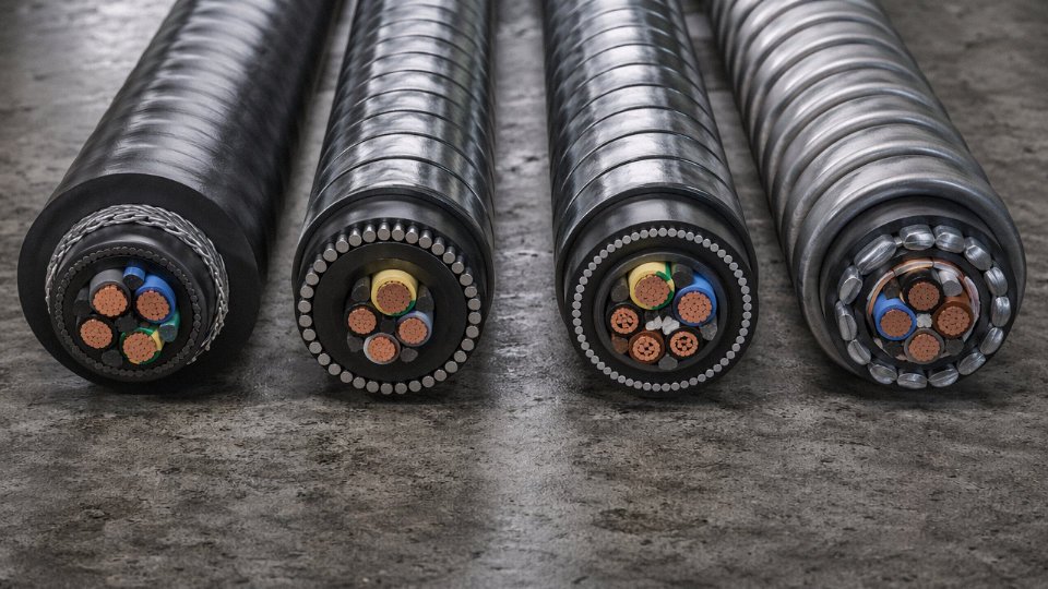
Interlocked aluminum armor (the standard MC cable construction) is the lightest option and the most conduit-friendly from a pure fill standpoint. For a 14 AWG two-conductor run, ODs typically land in the 0.55–0.65 in range. The interlocked profile does add some variability — the spiral ridges create slightly more friction against conduit walls than a smooth jacket, which matters on runs over 60–70 ft with multiple bends.
Corrugated aluminum armor sits between interlocked aluminum and steel wire armor in terms of rigidity and crush resistance. It handles RMC or IMC reasonably well; the concern is in small-bore PVC conduit where the corrugated profile can snag on joints if the conduit wasn’t deburred properly. In practice, runs through Schedule 80 PVC in chemical environments usually go fine as long as you use a quality wire-pulling lubricant — the Ideal Yellow 77 or equivalent, not cheap soap.
Steel wire armor (SWA) is a different animal. A 95 mm² three-core SWA cable can have an OD of 50 mm or more, and the weight per meter is roughly 4–7 kg/m depending on conductor size and insulation. This matters enormously in conduit fill calculations because you’re not just checking cross-sectional area — you’re checking whether the conduit support structure can handle the combined dead weight. SWA also gives you the best EMI shielding of the four armor types and genuine mechanical protection in mining or petrochemical trenching applications. The tradeoff is termination complexity and cost.
Steel tape armor (STA) is common in control cable applications — Jinda’s KYJVP2 shielded control cable with STA being a typical example — where the armor is more about rodent protection and moderate crush resistance than high tensile strength. ODs are more predictable than SWA, and the smooth tape profile pulls cleanly through EMT or PVC. For data center auxiliary control runs or instrumentation wiring routed through tray-to-panel conduit stubs, STA is often the right call.
Conduit Material Selection: It’s Not Just About the Pipe
RMC (rigid metal conduit, also called GRC) gives the highest crush resistance and is the right choice when the conduit itself is taking physical abuse — loading dock walls, machine bases, areas where forklifts occasionally win arguments. The trade-off is weight during installation and cost per foot, which runs noticeably higher than EMT in most North American markets. When you’re pulling SWA cable through RMC, account for the higher surface friction of steel-on-steel contact; you’ll need more lubricant and possibly intermediate pull points on runs over 100 ft.
IMC splits the difference — roughly 30–40% lighter than RMC, same thread form, acceptable for most industrial environments. Common choice in manufacturing plants where the conduit is exposed but not in truly severe mechanical zones.
EMT is the workhorse for indoor commercial and light industrial runs. It’s entirely appropriate for interlocked MC cable and STA control cables. The thinner wall does mean you’re getting less armor-on-conduit crush protection, which is usually fine inside a panel room but worth thinking about in a compressor bay.
Rigid PVC Schedule 40/80 introduces a chemical compatibility question that metallic conduit doesn’t. PVC conduit is broadly compatible with PVC-jacketed armored cable, but LSZH-jacketed cables — increasingly specified in marine, offshore, and transit applications — have a higher surface friction coefficient against PVC conduit walls than standard PVC-on-PVC contact. Expect pulling tension to increase by roughly 15–25% compared to a PVC jacket in the same conduit run. This isn’t a show-stopper, but it affects your wire-pull calculation and your decision about intermediate pull boxes.
HDPE duct, common in direct-buried and underground utility applications, pairs well with PE-jacketed or LSZH-jacketed SWA cable. The smoother interior surface of HDPE versus PVC actually reduces friction slightly on long pulls. The bigger issue with HDPE is that it’s not typically considered a grounding path, so your armor-to-ground continuity has to be handled at terminations.
LSZH-jacketed armored cable generates higher pulling tension in PVC conduit than standard PVC-jacketed cable of the same ODTrue
LSZH jacket compounds typically have a higher coefficient of friction against PVC conduit walls — measured values in cable installation engineering references run roughly 0.35–0.45 for LSZH-on-PVC versus 0.25–0.35 for PVC-on-PVC — increasing calculated pulling tension on longer runs with multiple bends.
Application Matrix: Matching System to Environment
| Application Environment | Recommended Armor Type | Recommended Conduit Type | Key Standard Reference |
|---|---|---|---|
| Hazardous area (Zone 1/2, Div 1/2) | Interlocked AL armor (MC-HL rated) | RMC or IMC — sealed fittings required | NEC Art. 501; IEC 60079-14 |
| Direct burial / underground | SWA (steel wire armor) | HDPE duct or Schedule 80 PVC | NEC Art. 300.5; IEC 60502-1 |
| Marine / offshore | SWA or corrugated AL with LSZH jacket | GRP or stainless rigid conduit where required | IEC 60092-353; IMO FTP Code |
| Data center (power + control) | STA control cable or interlocked MC | EMT or PVC Schedule 40 | NEC Art. 645; TIA-942 |
| Mining | SWA, heavy-duty | RMC with extra-heavy fittings | NEC Art. 502; IEC 60079-14 |
| Petrochemical / refinery | SWA or corrugated AL, LSZH jacket | RMC (stainless in H₂S zones) | NEC Art. 501; API RP 14F |
Jinda Product Lines Relevant to Conduit Installation
Jinda’s YJLHV (aluminum conductor, cross-linked PE insulated, steel wire armored, PVC sheathed) covers voltage ratings from 0.6/1 kV through 6/10 kV and up to 26/35 kV for medium-voltage feeder applications. Conductor sizes run from 25 mm² up to 400 mm² for the power feeder range, and the SWA construction makes it suitable for direct burial or conduit-in-trench installations in heavy industrial and utility projects. At the larger conductor sizes, always verify conduit fill against actual OD values from the product datasheet — published ODs at 240 mm² and above can easily push you into the next trade size of conduit.
The KYJVP2 shielded control cable with steel tape armor handles 450/750 V instrumentation and control circuits where both EMI shielding and moderate mechanical protection are needed. It pulls cleanly through EMT or Schedule 40 PVC and is a practical choice for running control signals through conduit stubs between junction boxes and panels in manufacturing plants.
For hazardous location work under NEC Article 501 or 502, the MC-HL rated cables in Jinda’s range carry the necessary listing for use in classified areas and are designed to interface with listed fittings in RMC or IMC systems. Don’t mix a standard MC cable into a hazardous area conduit run assuming the conduit provides the protection — the cable itself must be appropriately rated for the classification.
Frequently Asked Questions About Armored Cable in Conduit
Is it a code violation to run MC cable inside EMT conduit?
No. NEC 330.10(A)(5) explicitly lists installation in conduit as a permitted use for MC cable. This is one of the most persistent misconceptions on the plant floor — inspectors occasionally flag it, installers sometimes argue about it, but the code is unambiguous. The confusion probably stems from the fact that MC cable is already a raceway system in its own right, so layering it inside another raceway feels redundant. Feeling redundant and being prohibited are two very different things.
NEC 330.10(A)(5) permits MC cable to be installed inside conduit without constituting a code violationTrue
NEC Article 330.10(A)(5) explicitly lists conduit as an approved installation method for MC cable; the combination is not prohibited and does not require a special waiver or engineering judgment to permit.
Do I need to derate ampacity when armored cable is pulled inside conduit?
Yes, and this catches people off guard. NEC 310.15(B)(3)(a) applies adjustment factors when more than three current-carrying conductors are grouped together — and when you pull armored cable through conduit, the conductors inside that armor count toward the bundle total. A 3-conductor MC cable already has three current-carrying conductors. Pull two of those cables through the same conduit and you’re at six, which triggers a 0.70 adjustment factor on the ampacity tables. Three cables, nine conductors: 0.50. The derating stacks fast. What makes this worse is that the armor itself adds thermal resistance; heat dissipation is measurably slower than it would be for individual conductors in conduit. Run the 310.15 calculation before you size breakers, not after you’ve already pulled the cable.
Can SWA cable be used in outdoor above-ground conduit runs?
Yes, and it’s a reasonable choice for exposed industrial runs subject to mechanical abuse. The practical requirement is UV-resistant conduit — either Schedule 40/80 PVC with a UV stabilizer package or HDG rigid steel — because the steel wire armor on SWA cable provides no UV protection for the polymeric jacket underneath. Conduit support spacing matters too; unsupported PVC conduit in direct sun can sag noticeably in climates above roughly 35°C ambient, which puts lateral stress on the cable at every support point.
What is the minimum conduit trade size for a single 4/0 AWG 3-conductor armored cable?
Using Jinda’s 4/0 AWG 3-conductor armored cable with an OD of approximately 1.85 inches (47 mm): the cable cross-sectional area works out to about 2.69 in². NEC fill tables for a single cable permit 53% fill, so minimum conduit interior area needs to be roughly 5.08 in², which corresponds to a 3-inch trade size EMT (interior area approximately 7.38 in²). A 2½-inch EMT interior area of about 4.79 in² falls short of the 53% single-cable limit. Go to 3-inch; don’t try to argue the 2½ past an inspector.
Can flexible conduit be used with armored cable?
FMC and LFMC are permissible for short transition lengths — NEC 348.20 generally caps FMC runs at 6 ft in most applications. The real operational issue is double-flex: armored cable is already somewhat flexible depending on armor type, and running it through FMC at equipment connections creates a mechanically redundant, difficult-to-support termination that tends to fatigue at the fitting over years of vibration. In practice, a short rigid nipple into the equipment knockout is cleaner and more reliable than FMC-over-armor for anything beyond a simple final connection stub.
Does installing armored cable inside conduit void the UL listing?
No. UL listings for MC cable (UL 1569) and for conduit products are independent — each product is listed on its own merits. The installation method combining them is governed by NEC, not by either product’s listing document. A UL-listed MC cable installed inside UL-listed EMT per NEC requirements is a fully compliant, fully listed installation.
How do I maintain a hazardous location conduit seal when armored cable enters?
This one requires attention. NEC 501.15 requires sealing fittings within 18 inches of enclosures in Class I hazardous locations, and that requirement doesn’t go away because you’re using armored cable. When MC-HL (MC cable listed for hazardous locations) enters a conduit system that terminates at a Division 1 or Division 2 enclosure, the conduit seal must still be installed and properly filled with sealing compound — the armor termination doesn’t substitute for it. The seal fitting goes on the conduit side; the MC-HL termination fitting handles the armor. Both are required. Skipping the seal fitting because “the cable already has armor” is a wiring method confusion that will fail inspection and, more importantly, fails the explosion-containment logic the rule exists to enforce.
Where can large-volume armored cable orders be sourced for conduit-routed projects?
For projects that involve significant conduit-routed armored cable quantities — think utility substations, petrochemical plant upgrades, or large industrial expansions where the cable schedule runs to hundreds of line items — sourcing from a manufacturer with both production depth and export experience matters. Jinda has been manufacturing and exporting specialty armored cables since 1987, with five production bases and over 470,000 m² of manufacturing capacity, currently supplying customers in more than 50 countries. For procurement managers putting together a project-specific cable schedule that mixes MC, SWA, and interlocked armor types across multiple conduit trade sizes, having a single-source technical team that can cross-reference ODs against conduit fill requirements and provide certified documentation for the relevant regional standards saves real engineering hours during submittal review.
Specification Checklist and Project Implementation Roadmap for Armored Cable in Conduit Systems
If you’ve worked through the fill calculations, grounding scheme, and product selection covered in the earlier sections, the next failure point is usually execution — someone in the field working from an incomplete handover package, or a procurement manager chasing lead time without confirming the cable OD against the conduit already in the ground. The checklist below is designed to close those gaps.
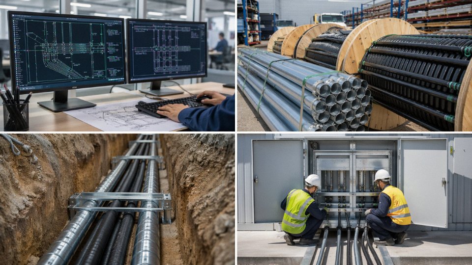
Phase 1 — Design Verification
Before a single line item hits the bill of materials, eight things need to be confirmed in writing.
First, nail down the code jurisdiction — NEC, IEC, or a national derivative — because the fill limits and armor recognition rules differ, and AHJ interpretations can vary even within the same country. Hazardous location classification comes next; if the installation falls under NEC Article 505 or ATEX Zone 1, your armor type and conduit sealing requirements change substantially. Run the conduit fill calculation using actual cable OD from the manufacturer datasheet (not a handbook estimate — ODs vary by armor style and jacket thickness), checking against the 53/31/40% limits for 1/2/3-or-more conductors per NEC Article 358, or the equivalent IEC guidance.
Check every bend point against the cable’s minimum bend radius — this is where office designs most often fail field reality. A 90-degree sweep that looks clean on a CAD drawing can violate bend radius on a 2-inch armored feeder. Ampacity derating for conduit-bundled runs is easy to overlook; account for it before you finalize conductor gauge. Confirm the grounding scheme: is the armor serving as the EGC, or is there a separate green conductor? That decision drives your bonding hardware specification. Document the AHJ approval path early — some jurisdictions require a variance for armor-in-conduit combinations that aren’t explicitly listed in local amendments.
Phase 2 — Procurement
Get the armored cable OD and weight per meter from the manufacturer’s actual datasheet, not a catalog table. Weight matters for vertical runs and for sag calculations in long horizontal conduit runs. Confirm armor material compatibility with the conduit environment — aluminum interlocked armor in a steel conduit buried in a coastal environment with chloride ingress is a galvanic problem waiting to happen. Request factory test reports certified to IEC 60502-1 or UL 1569 as applicable; a declaration of conformity without test data is not the same thing.
Jacket color coding against local standards is a detail that gets missed on international projects — what reads as a neutral in one country is a phase conductor in another. Delivery lead time needs to be checked against the conduit installation schedule, not just the overall project completion date; armored cable arriving after conduit is enclosed in a slab is a serious sequencing problem.
Jinda provides pre-project conduit fill calculation support and supplies certified IEC/UL test reports as part of its standard technical service package.True
This service is offered by Jinda's R&D and sales engineering teams to support specifiers and procurement managers during project design and tendering phases.
Jinda’s sales engineers can supply a conduit fill schedule specific to the cable type and trade size combination you’re specifying — that’s worth requesting early rather than building your own table from scratch.
Phase 3 — Installation Quality Control
Before the pull, verify the installed conduit trade size physically matches the design — substitutions happen in the field without paperwork. Inspect conduit interiors for burrs, particularly at couplings and field-cut ends; armor braid or interlocked armor will catch on a burr under tension and either strip the jacket or damage the armor itself. Confirm lubricant compatibility with both the jacket material and the conduit lining — some pulling compounds attack PVC jackets over time, which matters in a buried or inaccessible run.
On pulls longer than roughly 50–60 ft, monitor pulling tension with a dynamometer. Tension limits for armored cable are tighter than for plain conductors because the armor can transfer force directly to the conductors if the grip isn’t properly distributed. After pull-in, inspect the full accessible length of armor for deformation or kinking. Finally, verify every bonding connection with a low-resistance ohmmeter — the target is under 0.1 Ω, and any reading above that warrants investigation before energizing.
Phase 4 — Documentation and Handover
As-built conduit fill calculations, not design-stage estimates, go into the handover package. Photograph every bonding connection before covers go on — this is cheap insurance against a dispute six months later. IR test records at 1000 V DC for MV cables and 500 V DC for LV cables, with pass/fail criteria clearly stated, need to be included. Cross-reference the cable schedule to conduit tag numbers so any future maintenance crew can trace a circuit without tearing apart a tray or a ceiling.
Jinda’s after-sales team provides on-site technical support for larger infrastructure projects across Asia, the Middle East, Africa, Europe, and the Americas — useful when you’re commissioning a multi-building industrial campus and need someone who knows the product to be present during the final IR testing phase rather than relying solely on a local contractor who has never pulled that specific cable type before.