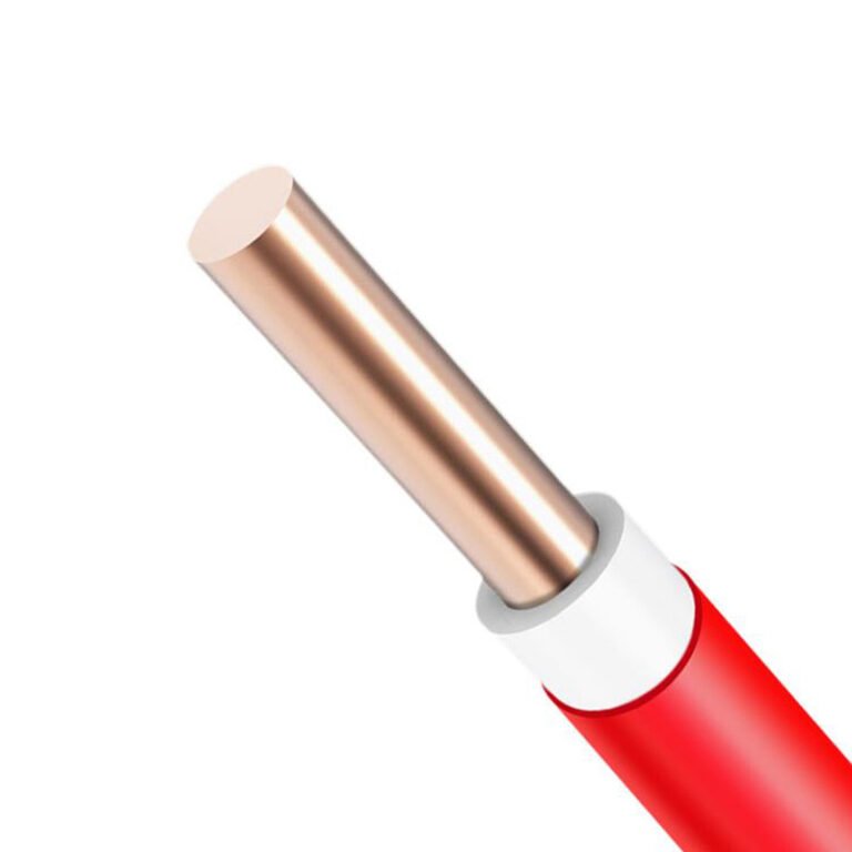
Specify the wrong cable ratio on a three-phase distribution run and you pay for it in one of three ways: you oversize the neutral and waste copper you’ll never need, you undersize it and watch harmonics or unbalanced loads push it into thermal failure, or you spec a fully symmetrical four-core where a 4:3 design would have done the job at meaningfully lower material cost. On longer cable runs — think 200 m or more inside a large factory or commercial building — that copper differential compounds fast enough to show up on a procurement budget.
4:3 cable is a four-core power cable where the neutral conductor is sized at three-quarters of the phase conductor cross-section. It is used in three-phase four-wire low-voltage distribution systems — typically 0.6/1 kV — where the neutral carries only residual imbalance current rather than full phase current. Common applications include factory floor power distribution, commercial building risers, and infrastructure feeder runs where load balance is reasonably well controlled.
What makes this cable worth understanding properly is that the ratio itself is an engineering decision, not an arbitrary standard — and the conditions that justify it are more specific than most purchasing specs acknowledge. Whether you’re sourcing cable for a new industrial facility, auditing an existing installation, or trying to shave legitimate cost out of a distribution project without compromising safety margins, the logic behind 4:3 designs is worth getting right.
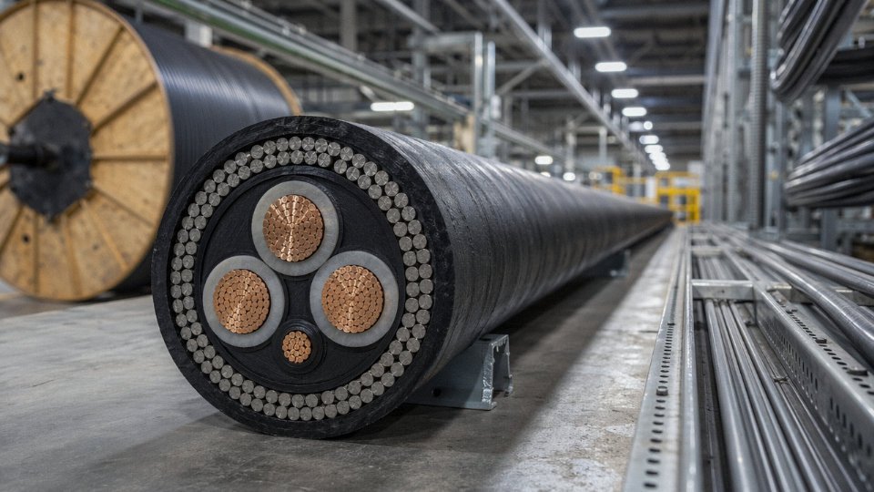
Three-Phase Four-Wire Power Distribution: The Primary Application of 4:3 Cable
The vast majority of 4:3 cable ends up in one place: underground low-voltage feeders and service entry runs on three-phase four-wire distribution systems. That’s not marketing — it’s just where the physics and the economics converge.
How the 3P+N System Justifies a Smaller Neutral
In a three-phase four-wire network, the three phase conductors carry the actual load current out to equipment. The neutral is doing something different. Under a perfectly balanced load — equal current on all three phases at unity displacement — the phasor sum of the three phase currents cancels to zero, and the neutral carries nothing. In practice no real installation is perfectly balanced, but a well-engineered LV distribution feeder serving a mix of commercial or residential loads will typically run within 10–20% imbalance across phases. At that level, neutral current sits well below half the phase current most of the time.
The worked numbers bear this out. Take a feeder with 150 mm² phase conductors rated around 250–285 A each (the exact figure depends on installation method, grouping, and ambient temperature per IEC 60364-5-52 Table B.52). Under moderate imbalance — say one phase at 240 A, one at 200 A, one at 210 A — the resultant neutral current comes out roughly 35–55 A. That’s well under the 188 A continuous rating of a 95 mm² conductor in the same conduit. Even a moderately stressed feeder with persistent imbalance rarely pushes neutral current above 50–75% of phase current, and a neutral sized at 75% of the phase cross-section handles that thermally without difficulty. IEC 60364-5-52 Section 524 explicitly permits reduced neutral conductor cross-section under these conditions, provided the load is predominantly linear and the imbalance is not chronic.
Where Utilities and DNOs Actually Specify It
Distribution network operators running underground LV networks — housing estates, commercial parks, light industrial zones, mixed-use urban developments — routinely call out 4:3 ratio cables in their feeder specifications precisely because the copper saving is real money at scale. The 15–25% reduction in copper mass relative to a symmetrical four-core cable of the same phase rating translates directly into lower material cost per metre and lower installed weight, which matters on long runs pulled through duct banks. A typical housing estate feeder run of 300–600 m, repeated across dozens of plots, adds up fast.
Substation outgoing feeders at 400 V are another common application. The cable connects the LV busbar through a metering panel and into the buried reticulation network. In this context the 4:3 configuration is almost standard; a symmetrical cable would be overspecified on the neutral and nobody wants to pay for copper that never carries current.
The Harmonic Caveat — Where 4:3 Becomes Wrong
This is where you have to pay attention. In installations with heavy non-linear loading — data halls, buildings full of switch-mode power supplies, or plants running large numbers of variable-frequency drives — the third harmonic and its odd triplen multiples (9th, 15th…) do not cancel in the neutral the way fundamental current does. They add arithmetically. The neutral can carry current equal to or exceeding the phase conductors, sometimes reaching 150–173% of phase current in severe cases.
In highly non-linear load environments with significant triplen harmonic content, a 4:3 ratio cable with a reduced neutral is electrically inadequate and can cause neutral conductor overheating.True
IEC 60364-5-52 and IEEE Std 141 (Red Book) both address this: where harmonic distortion is significant, the neutral must be sized equal to or larger than phase conductors. The 4:3 ratio is only appropriate where load is predominantly linear and imbalance is moderate.
A VFD-heavy machine shop or a server room is not the right place for 4:3 cable on the feeder. Those applications need a 1:1 symmetrical four-core, or in bad cases a dedicated neutral upsized beyond the phase conductors. Getting this wrong doesn’t fail immediately — the neutral runs warm for months, insulation degrades gradually, and eventually you get a neutral fault that takes the whole feeder down. Harder to diagnose than a clean overcurrent trip.
Design Standards That Govern the Decision
IEC 60364-5-52 is the primary reference for conductor sizing in LV installations and directly governs neutral sizing decisions in European and most export markets. IEEE Std 141 (the Red Book) covers industrial power distribution in North American practice and gives similar guidance on neutral sizing relative to load balance and harmonic content. Many regional grid codes — particularly those derived from CENELEC harmonized documents — incorporate the IEC 60364 framework by reference and allow the reduced neutral explicitly for balanced distribution feeders.
The design rule, distilled: confirm your load is predominantly linear, verify imbalance stays within reasonable bounds, and 4:3 is technically sound and economically the better choice. If either condition is uncertain, measure before you specify.
Industrial Facilities and Commercial Buildings: Installation Environments and Cable Routing Methods
Where a 4:3 cable ends up physically — buried under a factory yard, clipped to a cable ladder in a warehouse, pulled through a duct bank under a city road — shapes almost every selection decision beyond the basic conductor sizing. The installation environment dictates armour type, sheath compound, derating approach, and in some cases whether the slightly reduced neutral diameter actually pays a measurable dividend at the project level.
Direct Burial Underground
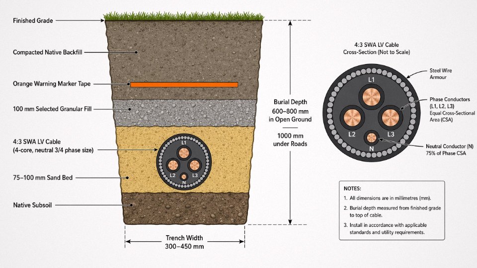
For outdoor runs between substations, switchrooms, and plant buildings, armoured 4:3 cable is the default. Steel wire armour (SWA) handles incidental mechanical loading from compaction or ground movement better than steel tape armour (STA) on longer runs; STA is more common on shorter, straighter domestic-style feeds where crush resistance rather than tensile strength is the concern. Burial depth for LV cables generally falls in the 0.5–0.8 m range in open ground under IEC 60364 and similar national codes, deepening to around 1.0 m or more under roads, driveways, or areas with vehicular traffic — the exact figure depends on the authority having jurisdiction and whether a concrete cover slab is included.
Bedding practice matters more than people admit on a busy civil site. A clean 75–100 mm sand bed under the cable, with the same or selected granular fill above it before backfilling with native soil, prevents point loads from stones that would otherwise deform armour wires over time. Bright orange marker tape at roughly 200–300 mm below finished grade is standard in most markets; some projects also specify a concrete tile or warning duct at that level for HV feeders, though for LV 4:3 distribution runs the tape alone is usually accepted.
Cable Tray and Ladder Rack in Manufacturing and Warehousing
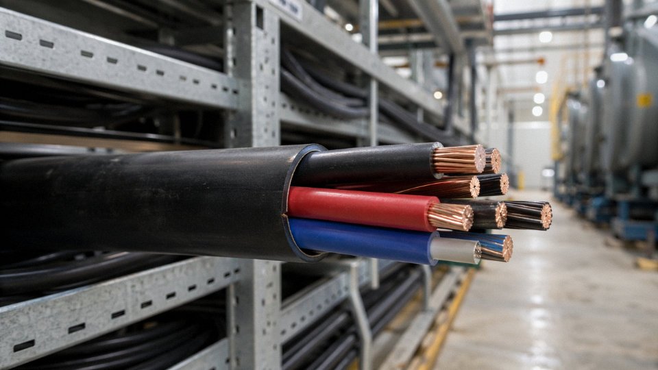
On a busy production floor or inside a distribution warehouse with dense cable populations on ladder rack, the slightly reduced overall diameter of a 4:3 cable compared to a fully symmetrical 4-core of the same phase conductor size is a real, not theoretical, advantage. Tray fill calculations under IEC or NEC are sensitive to cross-sectional area; shaving even a few percent off the cable’s footprint can mean fitting one additional circuit on an existing tray run without a costly tray upgrade. Derating for grouped cables applies regardless — typically starting around 0.8 for three or four circuits touching on a fully enclosed tray, dropping further for larger groups — and good spacing between cables on a ladder rack (25–50 mm where possible) keeps thermal performance closer to the rated values. In practice, plants running high-harmonic loads should not ignore the reduced neutral even here; a 4:3 ratio that seemed adequate at design stage can be marginal if the load profile shifts.
Conduit and Duct Bank Systems
Commercial buildings and infrastructure tunnels — road underpasses, airport aprons, rail yard cable routes — commonly use PVC or HDPE duct banks. The 4:3 configuration reduces conduit fill percentage by a small but useful margin compared to a 4-core with four equal conductors, which can lower pulling tension on long pulls. On a 100 m pull through a 90° swept bend in 63 mm conduit, the difference in calculated pulling force between a symmetrical and a 4:3 cable of the same phase cross-section can be 5–12%, depending on cable weight and coefficient of friction with the conduit wall. That margin sometimes decides whether a pull is feasible with a standard capstan or requires a larger machine on site.
A 4:3 cable has a smaller overall diameter than a fully symmetrical 4-core cable of the same phase conductor size.True
Because the neutral conductor is sized at 3/4 of the phase conductor cross-section, the neutral is physically smaller, reducing the overall cable diameter and weight compared to a 4-core cable with four equal conductors of the same phase rating.
Vertical Riser Shafts in High-Rise Buildings
Riser shafts concentrate risk. A cable fire in a vertical shaft can propagate through multiple floors faster than almost any other building scenario, which is why fire-resistant (FR) and low-smoke zero-halogen (LSZH) sheath variants dominate in this environment. Under EN 50575 (the Construction Products Regulation performance framework), cables installed in buildings across Europe must carry a declared reaction-to-fire class — Eca for basic flame propagation, up to Dca or Cca for buildings where the cable route itself is a life safety concern. Most specifiers in high-rise commercial and residential projects now call for at minimum Dca-s2,d1,a1 on main riser feeds. The 4:3 configuration is available in LSZH sheathed versions from most serious manufacturers; the key is confirming that the declared CPR class covers the actual installed condition, not just the cable tested in isolation.
Offshore and Marine Applications
Offshore platforms, port distribution boards, and shipboard secondary distribution all impose conditions that onshore industrial cable rarely faces simultaneously: continuous vibration, hydrocarbon contamination, salt spray, and the need to minimise cable mass and tray loading on structures where every kilogram is costed. Armoured 4:3 cables for these environments are specified to IEC 60092 (electrical installations in ships), which mandates specific flame-retardant performance, oil and mud resistance for the outer sheath, and construction details that differ from standard industrial armoured cable. The slightly lighter weight of a 4:3 versus a fully symmetrical 4-core is a minor but genuine factor in offshore weight budgets, particularly on topsides tray runs that can extend several hundred metres. Mud-resistant compound sheaths — typically a modified PVC or special elastomer — are worth specifying explicitly on procurement documents rather than relying on a generic “oil resistant” description, because the two are not the same thing and not all suppliers treat them as equivalent.
Conductor Materials, Insulation Systems, and Armour Options Compared for 4:3 Cable
Getting the specification right before you raise a purchase order saves far more time than correcting it after the cable is on site. The construction variables below are interdependent — change the insulation and you change the current rating; change the conductor material and you change the jointing procedure at every termination box. Each choice carries consequences.
Copper vs. Aluminium Conductors
Copper runs at roughly 58 MS/m conductivity against aluminium’s ~35 MS/m. In practice that means an aluminium conductor needs to be one standard size larger — sometimes two — to carry the same current as its copper equivalent. A 95 mm² copper phase conductor will comfortably match a 120 mm² aluminium conductor in most ambient-temperature burial scenarios, give or take derating for grouping and soil thermal resistivity.
The economics flip depending on cross-section. Below 25 mm², aluminium rarely makes sense: the jointing hardware, the bimetallic lugs, the extra conduit diameter, and the labour time all eat the material saving. At 35 mm² and above — and especially from 70 mm² upward — the cost gap widens enough to justify aluminium seriously. Aluminium cable at 95 mm² phase is often 30–45% lighter than the copper equivalent, which matters on long cable tray runs where cumulative load affects tray rating and support spacing.
One thing procurement managers sometimes underestimate: aluminium oxidises immediately on cut surfaces. Every joint and termination needs proper compound application and oxide-disrupting lugs. Skip that step and you get high-resistance connections that run hot and eventually fail. Not a reason to avoid aluminium — just a reason to write the jointing procedure into the installation specification.
Insulation Systems: PVC, XLPE, and EPR
PVC insulation is cheap, widely available, and adequate for standard 0.6/1 kV LV distribution in moderate ambient conditions. Its practical ceiling is around 70–90°C conductor temperature depending on the specific compound, and service life is typically in the 20–30 year range — shorter at the upper end if the cable runs consistently warm. For anything above 1 kV, or where you need long-term reliability in a hot switchroom, PVC starts to look like the wrong choice.
XLPE (cross-linked polyethylene) is the workhorse for serious industrial and MV applications. It maintains rated performance at 90°C continuous and can survive short-circuit temperatures up to around 250°C, which is why it dominates 6/10 kV and 8.7/15 kV medium-voltage 4:3 cables. Service life expectancy runs 40 years and beyond with good installation practice — meaningfully longer than PVC when the cable is loaded to near its rating regularly. The current-carrying capacity advantage over PVC in the same cross-section is typically 10–15%, depending on installation method.
EPR (ethylene propylene rubber) is the specialist choice for cold climates or highly flexible applications. It stays pliable at temperatures well below freezing — relevant for Nordic outdoor installations or refrigerated warehouse feeds where PVC becomes brittle and prone to cracking during winter installation work. EPR also handles wet environments and ozone exposure well. It costs more than XLPE, usually noticeably so, and that’s why you don’t see it used as a default.
Armour Options and Their Real-World Roles
Steel wire armour (SWA) is the standard for direct burial and most industrial tray installations where mechanical damage risk is real. The steel wires also serve as a fault current return path — relevant when designing earth fault loop impedance. Steel tape armour (STA) is a cost-saving option for installations with lower mechanical stress: indoor trunking, protected trenching with well-graded backfill. It’s adequate in the right context but offers noticeably less crush resistance than SWA.
Aluminium wire armour (AWA) solves two problems SWA creates: it eliminates eddy current losses in single-core cables (not directly relevant to 4:3 multicore, but it matters for large-section feeders), and it significantly cuts installed weight on long aerial or overhead-tray runs. AWA also avoids the mild magnetic interference SWA generates near sensitive instrumentation panels, something process plant engineers occasionally flag.
XLPE-insulated 4:3 cables deliver 10–15% higher current-carrying capacity than PVC-insulated cables of the same conductor cross-section under identical installation conditions.True
XLPE permits a higher maximum conductor operating temperature (90°C continuous vs. 70°C for standard PVC), and since current-carrying capacity scales with allowable temperature rise above ambient, the same conductor cross-section carries proportionally more current. This is documented in IEC 60502 and confirmed by standard derating tables used across the cable industry.
Outer Sheath Selection
PVC outer sheath is fine for most applications and keeps cost down. For plant rooms, tunnels, cable-dense switchrooms, or anywhere that a fire producing dense halogenic smoke could trap personnel, LSZH (low smoke zero halogen) sheath is the responsible specification — and in many jurisdictions it’s a code requirement. LSZH costs roughly 10–20% more than standard PVC outer sheath at similar cross-sections, though that varies with compound pricing cycles.
HDPE sheath is worth specifying for direct burial in aggressive soils — high moisture, clay, or chemically contaminated ground. It resists moisture ingress and abrasion better than PVC over a decades-long burial period. For process plant environments with chemical splash risk, you’re looking at speciality sheath compounds: CSP (chlorosulphonated polyethylene) or PCP for oil and solvent resistance, or thermoplastic polyurethane (TPU) where mechanical abrasion combines with chemical exposure.
Quick-Reference Specification Matrix
| Conductor | Insulation | Armour | Voltage Grade | Approx. Current Rating — 95 mm² Phase (buried, 20°C) | Primary Suitability |
|---|---|---|---|---|---|
| Copper | PVC | SWA | 0.6/1 kV | 205–230 A | General LV distribution, cost-sensitive commercial |
| Copper | XLPE | SWA | 0.6/1 kV | 230–255 A | Industrial LV, frequent full-load operation |
| Copper | XLPE | SWA | 6/10 kV | 230–255 A | MV substation feeders, process plant |
| Aluminium | XLPE | SWA | 0.6/1 kV | 175–200 A | Long LV runs, cost-driven procurement ≥70 mm² |
| Aluminium | XLPE | AWA | 0.6/1 kV | 175–200 A | Weight-critical tray runs, instrumentation proximity |
| Copper | XLPE | STA | 0.6/1 kV | 230–255 A | Protected indoor/trunking, lower mechanical risk |
| Copper | XLPE | SWA | 0.6/1 kV | 230–255 A (LSZH sheath) | Tunnels, switchrooms, people-occupied enclosed spaces |
Current ratings depend on soil thermal resistivity, grouping factor, ambient temperature, and depth of burial — treat the table as a starting bracket, not a final design figure. Always run the full IEC 60287 or applicable national standard calculation for the specific installation geometry.
Sizing and Selection Calculations: How to Specify the Right 4:3 Cable for Your Project
Getting the conductor size right on a 4:3 cable isn’t complicated, but it is sequential — skip a step or use a shortcut and you’ll either over-spend on copper or, worse, trip protection devices during a demand peak six months after commissioning. Here’s how to work through it properly.
Step 1 — Calculate the Design Current (Ib)
For a three-phase load, the full-load current is:
I = P / (√3 × V × PF × η)
Take a realistic example: a 200 kW motor feeder at 400 V line-to-line, power factor 0.85, motor efficiency 0.93. Plugging in: I = 200,000 / (1.732 × 400 × 0.85 × 0.93) = roughly 364 A. That’s your design current Ib. Keep the raw number; don’t round it yet.
One thing engineers sometimes miss here — if the feeder serves multiple loads rather than a single motor, apply a diversity factor. Diversity values of 0.65–0.85 are typical for industrial distribution boards, depending on the mix of loads and shift patterns. The exact factor depends on your load schedule, not a textbook default.
Step 2 — Tabulated Current-Carrying Capacity (Iz) from IEC 60364-5-52
Pull the appropriate table from IEC 60364-5-52 for your installation method. Method D (direct buried in ground, 0.7 m depth) and Method E (single layer on a cable tray, free air) give meaningfully different base ratings — often 15–25% apart for the same conductor cross-section, depending on cable construction. You need Iz ≥ Ib before any derating. At this stage you’re choosing a candidate size, not the final answer.
Step 3 — Apply Derating Factors
This is where direct-burial projects go wrong most often. The IEC reference soil thermal resistivity is 1.0 K·m/W. Dry sandy soils in arid climates commonly run 2.0–3.0 K·m/W, which can drop the rated current by 20–30% compared to the table value. Wet clay near a water table might actually perform better than the reference — but don’t count on it; test the site if the run is long and the feeder is critical.
Stack your correction factors multiplicatively: ambient temperature correction (Ca), grouping factor for parallel circuits (Cg), soil thermal resistivity (Cs if buried). A 95 mm² phase conductor that carries 270 A in free air at 30 °C might only safely carry 180–200 A when buried in a trefoil group of three circuits through dry sandy ground at 40 °C ambient. That’s a big difference.
Step 4 — Voltage Drop Check
IEC 60364-5-52 recommends keeping voltage drop within 3% for lighting circuits, 5% for power circuits. Calculate using resistance and reactance values (mΩ/m) from the cable manufacturer’s datasheet — not generic tables, because conductor stranding, insulation material, and operating temperature all shift the actual values. For the 200 kW example on a 150 m run, a 95 mm² copper conductor at operating temperature might show a phase voltage drop around 3.8–4.2%, depending on reactance contribution. Stepping to 120 mm² typically brings it under 3.5%. Run both calculations before committing to a size.
The neutral conductor in a 4:3 cable carries current only from load imbalance and zero-sequence components under normal conditions, so its voltage drop is rarely the binding constraint — unless harmonics are significant, which is covered below.
Step 5 — Short-Circuit Withstand
Verify thermal withstand using the adiabatic equation: k²S² ≥ I²t. For PVC-insulated copper, k = 115; for XLPE, k = 143. With a prospective fault current of, say, 25 kA and upstream protection clearing in 0.1 s, the minimum phase conductor cross-section works out to roughly 69 mm² for PVC — so 70 or 95 mm² would cover it.
The reduced neutral is the weak point here. A 75% neutral on a 95 mm² circuit gives 70 mm² equivalent, which is adequate for phase-to-neutral faults on balanced systems. But on circuits with significant third-harmonic loading — VFDs, UPS systems, large switched-mode power supplies — neutral current can approach or exceed phase current. In those cases, specify a full-size neutral or at minimum verify the upstream neutral protection setting explicitly.
Under IEC 60364-5-52, a 4:3 cable's reduced neutral cross-section is adequate for balanced or mildly unbalanced three-phase four-wire circuits but requires engineering review when total harmonic distortion exceeds approximately 15–20% on the neutral conductor.True
IEC 60364-5-52 and IEC 60364-4-43 both flag harmonic-rich environments (particularly high third-harmonic content from non-linear loads) as conditions where the neutral conductor may carry current exceeding the phase conductors, negating the design assumption behind the 4:3 ratio and potentially causing overheating of the undersized neutral.
Common Sizing Mistakes Worth Calling Out
Under-specifying the neutral for harmonic-rich loads is the most expensive mistake in practice — a burnt neutral in a distribution board is a full shutdown, not a partial one. Ignoring soil thermal resistivity on direct-burial runs longer than 50–80 m is a close second; it’s astonishing how often this gets defaulted to the IEC reference value on a specifier’s desk without a soil report. And failing to build in a growth margin is a procurement regret that shows up reliably at the three-to-five-year mark. A 20–25% margin on Ib before selecting conductor size costs relatively little in material and nothing in installation labor — ripping out a cable route to upsize two years later costs a great deal of both.
Renewable Energy, EV Infrastructure, and Emerging Applications Driving 4:3 Cable Demand
The grid is changing faster than most cable specifications committees can keep up with. Solar farms, battery storage yards, EV charging forecourts, and underground smart-grid feeders all share one structural reality: they run on three-phase four-wire distribution, often at medium voltage, over long distances, with demanding sheath requirements. That’s precisely the territory where 4:3 cable earns its place.
Solar PV Plants and Battery Energy Storage Systems
Ground-mounted utility-scale solar installations typically use 4:3 XLPE armoured cables at 6/10 kV or 8.7/15 kV to tie multiple inverter stations back to the main step-up substation. The collection network layout — strings of inverters daisy-chained or radially connected to a central HV point — means cable runs of 500 m to well over 2 km are common, buried directly in sandy or compacted-soil trenches. Sheath requirements here are not optional niceties. UV degradation matters for above-ground sections near combiner boxes, and rodent attack (particularly from rats in agricultural-land sites) is a genuine failure mode that pushes specifiers toward a PE outer sheath over an HDPE or hardened compound rather than standard PVC. BESS container connections, where the cable feeds AC output from a large battery inverter to the collection bus, are usually shorter runs but carry significant cyclic loading — the cable sees daily charge/discharge thermal cycling, so XLPE’s superior thermal stability over PVC is the real argument for the material choice here, not just voltage rating.
Wind Farm Onshore Collection Circuits
Onshore wind projects bury 4:3 armoured cables — typically SWA or double steel tape armour depending on soil movement risk — between each turbine transformer pad and the 33 kV or 66 kV collection substation. Pulling tension is the practical problem nobody fully appreciates until they’re standing at a joint bay at 2 a.m. in February. On long runs, say 800 m to 1,500 m between joint bays, the cumulative sidewall pressure through any bends can easily exceed what the armour wires tolerate if the drum setup isn’t calculated carefully. Joint bay spacing in wind farm designs usually runs 500–800 m, depending on terrain and the installer’s jointing capacity, and each joint represents a potential weak point, so minimising their count by specifying the longest practical drum lengths is standard procurement practice. The 4:3 ratio matters here for the same reason it does in conventional LV distribution: the neutral current in a balanced wind farm collection feeder is genuinely small, and oversizing it wastes copper in routes that can stretch several kilometres per turbine string.
EV Charging Infrastructure
Three-phase AC charging at Type 2 outlets — 22 kW single-point, or 43 kW in older three-phase AC fast-charge configurations — seems modest until you aggregate demand across a depot with 40 or 60 charge points. A logistics fleet charging depot with 50 × 22 kW outlets running at even 60–70% simultaneous demand factor draws roughly 660–770 kW of three-phase load, which pushes feeder sizing toward 185 mm² or 240 mm² phase conductors depending on run length and ambient temperature. At that scale, the neutral in a well-managed EV depot is genuinely lightly loaded — the on-board charger electronics present a reasonably balanced load — so the 4:3 neutral sizing holds up technically and trims cable cost meaningfully across what can be hundreds of metres of trench from the substation to the forecourt.
Three-phase Type 2 AC charging stations draw balanced three-phase loads, making the reduced neutral conductor in 4:3 cable technically appropriate for EV depot distribution feeders.True
Standard IEC 61851-compliant three-phase AC EV chargers draw current across all three phases simultaneously; with multiple chargers aggregated on a feeder, the neutral current remains low relative to phase current, consistent with the 4:3 cable design assumption.
Smart Grid and Microgrid Distribution
Urban ring-main feeder projects — the kind tied to automatic fault isolation via remote-controlled RMUs — almost exclusively use underground 4:3 cables now. The ring configuration means each section of cable can be isolated and re-energised from either direction, and the cable spec has to accommodate that bidirectional loading pattern without degradation. In practice, 95 mm² to 150 mm² 4:3 XLPE cables at 0.6/1 kV or 6/10 kV handle most urban microgrid distribution segments, with armoured variants mandated wherever shared utility trenches create mechanical risk from third-party excavation.
Data Centers: Where to Use It and Where Not To
Data center power distribution is worth a careful note. High-harmonic environments — server UPS systems feeding switched-mode power supply loads — can drive neutral currents to 150–180% of phase current, which makes any reduced-neutral cable the wrong choice for IT floor distribution. That’s well-established and was addressed in an earlier section. The application where 4:3 cable does belong in a data center is the generator tie-cable and balanced UPS output feeder to PDUs, where load management is actively controlled and neutral current stays within design limits. The distinction matters at the procurement stage: one building, two different cable specifications, and confusing them creates a thermal overload risk that won’t show up until the facility is under full production load.
International Standards, Testing Protocols, and Quality Certifications for 4:3 Cable
Specifying a 4:3 cable without anchoring that specification to the right standards is how procurement teams end up receiving product that passes factory inspection but fails in service — wrong conductor resistance class, inadequate insulation thickness for the actual system voltage, or flame-propagation performance that never matched what the project drawings assumed. Getting the standards framework right before you issue an RFQ saves rework later.
Core IEC Standards That Govern 4:3 Cable Construction and Performance
IEC 60502-1 covers low-voltage power cables rated up to and including 0.6/1 kV — the construction rules, dimensional tolerances, and type-test requirements for the majority of 4:3 cables used in building distribution and industrial plant feeders. IEC 60502-2 extends that framework up to 30 kV, which applies to medium-voltage 4:3 variants used in utility substations and large industrial step-down circuits. Both standards define insulation thickness, oversheath properties, and the full type-test sequence a compliant cable must survive before it can be sold into a serious project.
IEC 60228 is the conductor standard — and it matters more than people often realize. It defines conductor classes (Class 1 solid, Class 2 stranded, Class 5 flexible), resistivity limits, and the measurement method. For a 4:3 cable where the neutral conductor is deliberately undersized relative to the phase conductors, confirming the neutral meets the correct Class 2 resistance limit for its actual cross-section is non-negotiable. A neutral wound from borderline-quality copper that drifts above the IEC 60228 resistance ceiling will cause measurable voltage imbalance under load — not immediately obvious, but cumulative.
IEC 60331 (circuit integrity under fire conditions) and IEC 60332 (flame propagation) address two different failure modes. IEC 60332-1 tests a single cable vertically; IEC 60332-3 tests bunched cables — the relevant one for cable trays in plant rooms and riser shafts. Fire-performance specification is where procurement teams most commonly under-specify. Stating “flame retardant to IEC 60332” without specifying the sub-part is functionally incomplete.
Regional Equivalents and Practical Overlap
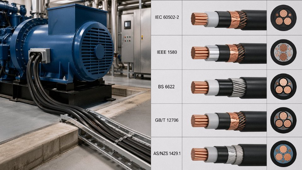
A cable fully compliant with IEC 60502-1 will generally satisfy BS 5467 (armoured XLPE) and BS 6346 (armoured PVC) in the UK with only minor cross-checks on sheath colour or marking requirements. Germany’s VDE 0276 series and France’s NF C 32-321 follow the same logic — IEC-compliant cables usually need only a documentation review rather than full re-testing for these markets. Russia and CIS countries under GOST R have historically been more prescriptive about local certification, though the underlying test methods are largely aligned with IEC. China’s GB/T 12706 mirrors IEC 60502 closely enough that a dual-marked cable (IEC + GB/T) is entirely feasible and increasingly common for export-oriented manufacturers.
Type Tests, Routine Tests, and What to Demand in a FAT Package
These three test categories are not interchangeable.
Type tests are performed once on a representative sample to prove the design is sound — they include full high-voltage withstand, bending, impact, crush, and for MV cables, partial discharge measurement (typically below 10 pC at 1.5× U₀ for XLPE-insulated designs). Routine tests run on every manufactured length: conductor resistance, high-voltage spark test on the insulation, and continuity. Sample tests sit between the two — performed on a batch basis, covering things like insulation thickness measurement and tensile properties.
When you issue a purchase order for a significant 4:3 cable supply, the Factory Acceptance Test package should include original type-test reports (not just certificates — the actual test data), routine test records for each drum, and a material traceability document linking conductor rod, insulation compound, and sheath compound to certified suppliers. If a supplier cannot produce traceable type-test reports from a recognized laboratory — KEMA, CESI, or equivalent — treat that as a red flag.
Third-Party Certification for Export Projects
European projects procured under the Construction Products Regulation require CE marking per EN 50575, which classifies cables by reaction-to-fire performance from Eca through B2ca. North American projects typically require UL listing, which involves a completely separate test protocol and annual factory audits — IEC compliance does not substitute. Marine and offshore installations usually specify DNV or ABS certification, which adds environmental and mechanical requirements beyond standard IEC type tests.
A cable bearing a CE mark under CPR (EN 50575) has been independently tested for reaction-to-fire performance and declared by the manufacturer against a harmonized European standard.True
CE marking under the Construction Products Regulation requires a Declaration of Performance backed by third-party testing for cables in classes above Eca. It is a legal declaration tied to specific fire-performance test results, not a general quality endorsement.
Jinda’s Quality Infrastructure
Jinda holds ISO 9001 certification across its production operations and carries national high-tech enterprise status in China — the latter requires demonstrated R&D capability and is audited periodically, not self-declared. The in-house test laboratory covers partial discharge testing, conductor DC resistance measurement, high-voltage AC withstand, and full IEC 60332 flame-propagation testing. Having this capability in-house rather than relying entirely on third-party labs shortens the feedback loop during production significantly; if a batch shows an anomaly during routine testing, the engineering team can investigate and respond without a two-week external lab queue.
With five production bases, Jinda can route orders to facilities with specific certification scopes — which matters when a project requires, say, GB/T 12706 marking for domestic Chinese delivery and IEC 60502-1 documentation for a parallel export shipment. Consistent quality at that scale depends on a unified QMS rather than site-by-site improvisation, which is where the ISO 9001 framework earns its keep in practice.
Procurement, Global Supply Chain, and Working With a 4:3 Cable Manufacturer at Scale
Sourcing 4:3 cable for a large project sounds straightforward until you’re three weeks from a site mobilization date and the specification your contractor submitted is missing half the data a manufacturer actually needs to produce the right product. Getting the purchase specification right at the start saves far more time than any expediting effort later.
Writing a Purchase Specification That Leaves Nothing Ambiguous
The minimum data set a manufacturer needs — and that a procurement team should insist on before issuing any RFQ — looks roughly like this: conductor material (copper or aluminum, plus conductor class per IEC 60228), cross-section in the notation that actually defines the cable construction (e.g., 3×95+1×70 mm²), voltage grade (e.g., 0.6/1 kV or 6/6 kV), insulation type (XLPE, PVC, EPR), inner bedding and armour specification (unarmoured, SWA, AWA, double steel tape), outer sheath compound and color, the governing standard (IEC 60502-1, BS 5467, HD 603, or project-specific), required drum length, and end-sealing method.
That last point — end-sealing — gets overlooked more often than it should. Drums shipped to humid port environments or stored on site for weeks before installation can absorb moisture at cut ends, and XLPE insulation is not forgiving about that. Specifying heat-shrink end caps as a contractual requirement rather than a hope costs almost nothing per drum and eliminates an entire class of post-installation failure.
Voltage grade and cross-section notation are the two fields where errors cause the most expensive rework. A specification that says “4-core 95 mm² XLPE SWA” without the ratio notation is technically incomplete — the manufacturer may quote a 4×95 mm² fully symmetrical cable, which is heavier, costs more copper, and may not match the project’s conduit fill calculations. Be explicit: 3×95+1×70 mm².
Lead Times and Production Planning
Standard LV sizes in common cross-sections — say, 3×50+1×35 mm² through 3×185+1×95 mm² in copper XLPE SWA — typically ship in 4–8 weeks from order confirmation, assuming conductor rod is in stock. Non-standard configurations, large MV variants, unusual sheath colors for a specific utility, or very high-volume orders (think several hundred drums for a substation rollout) push lead times to 10–16 weeks. That range depends heavily on whether the conductor rod market is under pressure; copper and aluminum rod availability has a direct effect on production scheduling that procurement teams in project-heavy regions often underestimate.
Jinda’s five production bases spread across China, with a combined footprint of 470,000 m², provide real scheduling flexibility — if one line is committed to a large export order, production of a parallel order can be allocated to a different facility rather than queuing behind it. For project-critical timelines, that kind of multi-site capacity is worth asking about explicitly when you’re evaluating suppliers.
Drums, Packaging, and Export Logistics
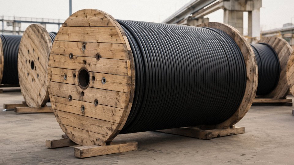
Standard drum lengths for LV 4:3 cable typically run 500 m to 1,000 m for heavier cross-sections (185 mm² and above) and up to 1,500–2,000 m for smaller sizes like 4 mm² and 6 mm², though exact lengths depend on drum capacity and the buyer’s jointing strategy. Fewer joints in a run is almost always preferable; if your trench run is 800 m, ordering 1,000 m drums and accepting a short offcut is usually cheaper than a mid-run joint.
Wooden drums destined for export must comply with ISPM 15 phytosanitary requirements — heat-treated or fumigated timber with the official mark. This is a customs compliance issue, not a suggestion; non-compliant packaging has been held at ports in Australia, the EU, and several Middle Eastern countries. Steel drums eliminate the ISPM 15 concern entirely and are worth specifying for projects shipping to jurisdictions with strict enforcement, accepting the higher per-drum cost.
Container loading efficiency matters on large orders. A standard 40 ft high-cube container typically accommodates 8–12 loaded cable drums depending on drum diameter, and an experienced logistics coordinator can optimize drum sizing to maximize container utilization and reduce freight cost per meter of cable.
Bulk Procurement and Long-Term Supply Agreements
For EPCs and utilities managing multi-year infrastructure programs — grid expansion, industrial park development, renewable energy rollouts — a framework supply agreement with a tiered volume pricing structure is usually more cost-effective than project-by-project spot procurement. Safety stock programs, where the manufacturer holds a defined quantity of specified cable ready for call-off within a short window (2–3 weeks rather than the standard lead time), suit utilities that face emergency replacement demand. Vendor-managed inventory arrangements go a step further, with the supplier monitoring stock levels and replenishing automatically against agreed minimum quantities. Jinda supports both models for qualified buyers, particularly those running procurement across multiple countries.
Jinda Special Cable Group serves customers in more than 50 countries from five production bases in ChinaTrue
This operational detail is stated in the company's published profile and is consistent with the scale of infrastructure described — 470,000 m² of manufacturing space and over 1,000 employees.
Technical Support Beyond the Purchase Order
The most useful thing a cable supplier can do on a complex project, beyond delivering product on time and to spec, is front-loading the technical work before the order is placed. Pre-project specification review, material take-off support (checking that the cable schedule matches the single-line diagram and conduit schedule), and facilitation of third-party witness testing at the factory — these services compress the back-end risk considerably. Installation teams occasionally encounter questions about termination compatibility, bending radius constraints on larger cross-sections, or drum handling procedures in cold weather; having a manufacturer’s technical contact who can respond within a working day is genuinely different from submitting a ticket to a distributor who will relay the question next week. That distinction matters most when the cable is already on site and the commissioning date is fixed.
Frequently Asked Questions About 4:3 Cable
These are the questions that come up repeatedly — from site engineers double-checking a substitution, from procurement managers reading a drum label for the first time, from contractors wondering why the neutral looks undersized. Answers below are direct.
Can I use a 4:3 cable where a balanced 4-core cable is specified?
In most balanced three-phase four-wire circuits, yes. The logic is straightforward: if the loads are reasonably balanced and the neutral carries only residual unbalance current, a neutral sized at 3/4 of the phase conductor handles it comfortably. That said, “balanced” is the operative word. Before making the substitution, confirm with the design engineer that the neutral current under the actual load profile won’t approach the reduced conductor’s rated current. Check the applicable installation standard for your jurisdiction — IEC 60364 and BS 7671 both have specific clauses on reduced neutral sizing. Don’t make this call on the site without a paper trail.
What does “3×95+1×70” mean on a cable drum label or datasheet?
Three phase conductors, each 95 mm², and one neutral conductor of 70 mm². The 70 mm² is roughly 73.7% of 95 mm² — close enough to the 3/4 ratio to sit firmly in the 4:3 classification. The drum label will also carry the voltage grade (typically 0.6/1 kV for low-voltage versions), the insulation system (XLPE, PVC, etc.), and the armour designation if applicable. None of that is embedded in the “3×95+1×70” notation itself, so read the full marking. A cable described only by conductor sizes without voltage grade is an incomplete specification — and a common source of procurement errors.
Is a reduced neutral safe for circuits feeding LED lighting or VFD-driven motors?
This is where engineers get burned. LED drivers and variable frequency drives (VFDs) are both significant sources of third-order (triplen) harmonics — 3rd, 9th, 15th — and unlike balanced fundamental-frequency currents, these harmonics do not cancel in the neutral. They add. In a circuit heavily loaded with LED luminaires or VFD-driven motors, neutral current can approach or even exceed phase current. For these loads, a full-size neutral — a symmetrical 4×equal cross-section cable — is the correct choice. IEC 60364-5-52 Annex C addresses this explicitly. Using a 4:3 cable on a VFD distribution board to save a few euros per meter is a false economy; neutral overheating, nuisance tripping, or insulation degradation are the realistic consequences.
Triplen harmonics accumulate in the neutral conductor rather than cancelling, meaning a reduced neutral is inappropriate for circuits with significant non-linear loads such as VFDs or LED drivers.True
In three-phase four-wire systems, 3rd-order harmonics (and their multiples) are zero-sequence quantities that sum arithmetically in the neutral rather than cancelling as balanced fundamental-frequency currents do. This is established physics documented in IEC 60364-5-52 Annex C and reinforced by field measurements on VFD installations.
How does the 4:3 cable compare in cost to a fully symmetrical 4-core cable?
Typically 8–18% less per meter, depending primarily on conductor material and the metal price at time of order. The saving is larger on copper cable than aluminium, simply because the absolute mass difference is more significant when copper is at USD 9,000–10,000/tonne. On a 10 km run of 3×95+1×70 Cu/XLPE/SWA, that difference is real money. The percentage swings with LME prices, so lock in pricing with your supplier close to order execution, not six months before.
What armour option is best for direct-buried 4:3 cable in rocky or stony soil?
Steel wire armour (SWA) over steel tape armour (STA), without much debate. Individual wires distribute point loads across the cable circumference; tape armour concentrates stress at any sharp stone edge. Pair SWA with a fine sand bedding and surround layer — 100 mm above and below is a commonly specified minimum — and marker tape at roughly 300 mm below finished grade. Skipping the sand bed on a rocky site is the kind of shortcut that produces an insulation fault two years later, usually in the most inconvenient section of the run.
Does Jinda supply 4:3 cable to international projects with CE or third-party test reports?
Yes. Jinda holds ISO 9001 certification and manufactures to IEC 60502-1 (low voltage) and IEC 60502-2 (medium voltage) as standard. For projects requiring Construction Products Regulation (CPR) compliance or independent verification, third-party type-test reports from accredited laboratories — KEMA, CESI, and others — are available. Specify the required standard, voltage grade, and any project-specific test requirements in the purchase order; the technical team can confirm which reports are current and whether additional witness testing is needed for your contract.