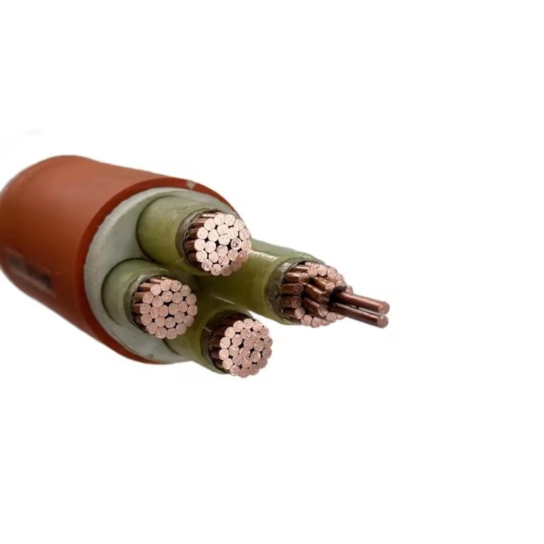
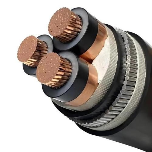
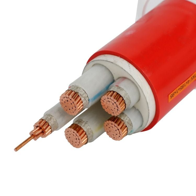
Cables that crack, stiffen, or develop intermittent faults after a few months of repeated flexing are almost never a material failure in the traditional sense — they’re a specification failure. Someone chose a Class 2 stranded conductor for an application that needed a Class 5 flexible one, and the difference shows up as nuisance tripping, unplanned downtime on a production line, or a welding cable that has to be replaced every quarter instead of running for years. The cost isn’t just the cable itself; it’s the labour to swap it, the scrap produced during an unscheduled stop, and — in food, pharma, or automated assembly — the compliance paperwork that follows every unplanned event.
Class 5 cables are flexible power and control cables built around finely stranded copper conductors that meet the wire-count and resistance requirements of IEC 60228 Class 5. A 16 mm² Class 5 conductor contains a minimum of 196 individual wires, compared to just 7 for a Class 2 conductor of the same cross-section. That fine stranding gives Class 5 cables the bend radius and fatigue resistance needed for hand-held tools, trailing leads, machine umbilicals, and any application where the cable moves repeatedly under service.
What’s easy to miss is the range of work Class 5 conductors actually cover — from a 0.5 mm² control wire in a pendant station all the way up to a 630 mm² welding or power feeder cable, all governed by the same IEC 60228 Table 4 resistance limits. The conductor geometry changes dramatically across that range, and so does the right way to terminate, route, and procure them.
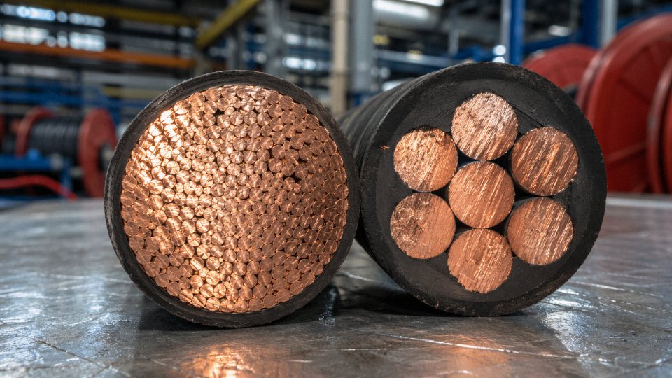
Class 5 Conductor Construction: Wire Count, Diameter Limits, and Stranding Geometry
IEC 60228 Table 4 is the primary reference document here. It sets both the minimum number of wires and the maximum diameter of each individual wire for every cross-section — two constraints that work together to define what a Class 5 conductor physically is. Getting either one wrong in production or incoming inspection means the conductor may not meet the flexibility performance the standard is trying to guarantee.
Wire Count and Maximum Wire Diameter by Cross-Section
The table below pulls the key figures directly from IEC 60228 Table 4. Engineers should treat the minimum wire counts as hard floors, not targets. Reputable manufacturers typically exceed the minimum by a small margin to maintain dimensional consistency across a production run.
| Nominal Cross-Section (mm²) | Min. Wire Count | Max. Individual Wire Diameter (mm) |
|---|---|---|
| 0.5 | 16 | 0.21 |
| 0.75 | 24 | 0.21 |
| 1.0 | 32 | 0.21 |
| 1.5 | 30 | 0.26 |
| 2.5 | 50 | 0.26 |
| 4 | 56 | 0.31 |
| 6 | 84 | 0.31 |
| 10 | 80 | 0.41 |
| 16 | 196 | 0.41 (uncompacted) |
| 25 | 196 | 0.41 |
| 35 | 276 | 0.41 |
| 50 | 396 | 0.41 |
| 70 | 360 | 0.51 |
| 95 | 475 | 0.51 |
| 120 | 608 | 0.51 |
| 150 | 756 | 0.51 |
| 185 | 925 | 0.51 |
| 240 | 1221 | 0.51 |
| 300 | 1525 | 0.51 |
| 400 | 2030 | 0.51 |
| 500 | 2537 | 0.51 |
| 630 | 3192 | 0.51 |
Why Maximum Wire Diameter Actually Matters on the Plant Floor
Thin individual wires are not just an aesthetic choice. Bending stress in a conductor scales with wire diameter — specifically, a thicker wire sees higher surface strain at the same bend radius. When you’re running a cable over a festoon system on an overhead crane, or feeding a robotic welder that cycles thousands of times per shift, fatigue cracking starts at the outer wires in the bundle and propagates inward. Keeping each wire below the IEC diameter cap distributes that cyclic stress across hundreds of elements rather than concentrating it in a few. A 16 mm² Class 5 conductor with 196 wires at ≤0.41 mm each will outlast a Class 2 equivalent in the same bending application by a wide margin — the Class 2 only requires 7 wires, which simply cannot absorb the same flex life.
IEC 60228 mandates a minimum of 196 wires for a 16 mm² Class 5 conductorTrue
IEC 60228 Table 4 specifies this as the minimum wire count for a 16 mm² Class 5 flexible conductor, versus just 7 wires for a Class 2 solid-stranded conductor of the same cross-section.
Stranding Geometry: Bunch, Concentric Rope, and Unilay
Three main geometries appear in Class 5 production, and the choice has real consequences for outer diameter and handling.
Bunch stranding twists all wires together in one operation with no defined layer structure. It produces the most flexible result and the smallest theoretical diameter, but the bundle isn’t perfectly round — fill factor is lower, and if you’re pulling into conduit, the oval profile can cause binding. Common in flexible control cables and portable cords up to roughly 10 mm².
Concentric rope stranding builds the conductor in defined concentric layers, each with a specific lay direction. This gives a more predictable, round cross-section and better fill factor, which matters when insulation wall thickness tolerances are tight. Larger cross-sections — 35 mm² and above — almost always use this geometry in practice.
Unilay strands all layers in the same lay direction and usually the same lay length. The result is extremely flexible with a very compact profile. It’s used in premium trailing cables and continuous-flex applications like tow chains (energy chains). The tradeoff is slightly higher tooling cost per production run, so you’ll rarely see it specified for general-purpose flexible wiring.
Annealed Copper and Why Hard-Drawn Wire Has No Place Here
Class 5 production uses annealed (soft-drawn) copper. IEC 60228 requires a minimum elongation-at-break of 20% for annealed copper conductors — that ductility is precisely what allows the fine wires to survive repeated bending without cracking at grain boundaries. Hard-drawn copper has higher tensile strength but elongation typically below 5%, which means it becomes brittle under cyclic flexing. Any supplier offering Class 5 cable with hard-drawn wire is producing something that may pass initial resistance testing but will fail in service. In my experience, this occasionally shows up in budget imports; ask for the material certificate and check the elongation figure.
Tinned Copper: Where It Applies and What It Costs You
Tinning each wire before stranding is standard practice in marine wiring, food-processing plants with regular washdowns, and chemical environments where bare copper corrodes quickly. The tin layer protects the copper surface and also makes soldering significantly easier at termination points. The slight tradeoff is a marginal increase in DC resistance — typically in the range of 1–3% higher than bare copper, depending on coating thickness, which still comfortably meets IEC 60228 Table 4 limits. The tinned variant remains fully IEC 60228 Class 5 compliant; the standard explicitly accommodates it.
Compact vs. Uncompressed Stranding
Compressed or compact Class 5 conductors are rolled or drawn after stranding to reduce the overall diameter by roughly 5–15% compared to an uncompressed bundle of the same cross-section. This matters when you’re pulling multiple cables through a conduit that’s already full, or where a smaller cable outer diameter allows a thinner insulation wall and reduces finished cable weight on a mobile machine. The flexibility is marginally reduced — the compression introduces some work-hardening at wire contact points — but for most industrial flex applications it remains adequate. If the cable is going into a continuous high-cycle flexing application like a cable carrier, specify uncompressed and be explicit about it in the purchase order, because some suppliers default to compact without flagging it.
Electrical Performance Parameters: Resistance, Current Capacity, and Voltage Ratings
Resistance is the number procurement engineers reach for first, and IEC 60228 Table 4 gives hard upper limits that any compliant Class 5 conductor must meet at 20°C. For copper conductors: 1.5 mm² sits at ≤13.3 Ω/km, 2.5 mm² at ≤7.41 Ω/km, 10 mm² at ≤1.83 Ω/km, and 50 mm² at ≤0.387 Ω/km. These are maximums, not targets — a well-drawn, cleanly annealed conductor will typically come in 2–4% below the limit, depending on wire drawing quality and the purity of the copper rod stock used.
IEC 60228 Table 4 specifies a maximum DC resistance of ≤13.3 Ω/km at 20°C for a 1.5 mm² Class 5 flexible copper conductor.True
This is the published resistance limit in IEC 60228:2004 Table 4 for Class 5 (and Class 6) copper conductors at 1.5 mm² cross-section, measured at 20°C.
Temperature Correction and Why It Matters in Service
Nameplate resistance is measured at 20°C. In a real installation — a cable tray on a summer afternoon, or a conductor running at 70°C inside a flexible conduit — resistance climbs, and so does voltage drop. The correction formula is:
R_T = R_20 × [1 + α(T − 20)]
For copper, α = 0.00393 K⁻¹. Worked out for a 1.5 mm² conductor running at 70°C: R_70 = 13.3 × [1 + 0.00393 × (70 − 20)] = 13.3 × 1.1965 ≈ 15.9 Ω/km. That’s a roughly 20% resistance increase over the nameplate value. On a 50 m flex drop to a machine tool, the additional voltage drop is small in absolute terms, but on a 200 m run feeding a precision servo drive, the difference is enough to push you into the next cross-section. Designers who skip this step and size cables on cold-state resistance alone sometimes find themselves troubleshooting nuisance trips after the plant heats up in July.
AC Resistance and VFD Applications
At 50 or 60 Hz, the skin effect in fine-stranded Class 5 conductors is essentially negligible. The individual wire diameters are small enough — typically 0.21 mm or less at 16 mm² — that the AC/DC resistance ratio stays within a fraction of a percent of unity. You can treat DC resistance figures as AC resistance for all standard power frequency work.
Above 400 Hz, the picture changes. Variable-frequency drives running at high carrier frequencies, induction heating equipment, and some aerospace ground support applications operate in ranges where the large surface area of a Class 5 conductor begins to show a measurable AC resistance penalty compared to a Class 2 conductor of the same cross-section. It’s rarely catastrophic, but it’s worth checking with your cable supplier if the application involves sustained operation above 400 Hz on conductors 35 mm² and larger.
Current-Carrying Capacity and Derating
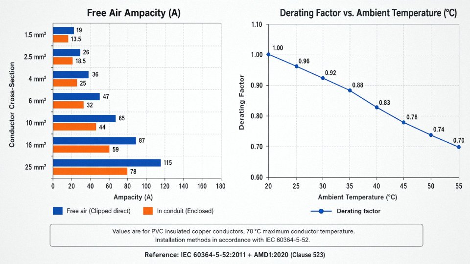
Ampacity for Class 5 cables is governed by the insulation system and installation method, not by conductor class directly. IEC 60364-5-52 provides the base current ratings and derating factors. In free air, a 2.5 mm² PVC-insulated flexible cable typically handles 24–27 A; bundled in a conduit with three loaded conductors, that figure drops to roughly 16–19 A depending on conduit fill and ambient temperature. At ambient temperatures above 30°C, apply the standard temperature derating factors — a 45°C plant floor in summer can cut rated current by 10–15%.
Voltage Ratings and Insulation Systems
Class 5 conductors appear across three common voltage designations: 300/500 V (lightweight control and appliance cables under IEC 60227), 450/750 V (general-purpose flexible power cables under IEC 60245), and 0.6/1 kV (heavier industrial flexible cables). The voltage rating is a property of the insulation system, not the conductor class itself — the same Class 5 stranding can be found under all three designations.
Insulation choice has a direct effect on outer diameter and weight, both of which matter for drag-chain and pendant applications where mass and bend radius are constrained. PVC is the workhorse — cheap, flame-retardant, easy to process — but adds more wall thickness than XLPE for the same voltage rating and ages faster under continuous flexing above 70°C. EPR handles heat and oil better and tolerates tighter repeated bends. LSZH compounds are now specified almost by default in public buildings, tunnels, and offshore platforms; they run slightly thicker and heavier than standard PVC at equivalent voltage ratings, which is worth factoring into conduit fill calculations on dense installations. Silicone insulation is a specialist choice — extremely flexible, rated to 180°C in some constructions, but mechanically fragile and expensive enough that it only makes sense when nothing else survives the environment.
Mechanical Flexibility Testing: Bend Cycles, Torsion, and Real-World Fatigue Life
Flexibility is easy to claim on a datasheet. Proving it under load, over millions of cycles, in real installation geometry — that’s where Class 5 construction earns its keep.
Standardized Bending Tests: What the Numbers Actually Mean
IEC 60227-2 and IEC 60245-2 define the bending test procedure for flexible cables. The mandrel diameter is set as a multiple of the cable’s outer diameter — typically 5× OD for cables up to around 12 mm, scaling upward for larger cross-sections, though the exact multiple depends on the specific product standard and insulation material. The cable is flexed back and forth over the mandrel for a defined number of cycles, usually somewhere in the 30,000–50,000 range for type-approval testing, though this varies by standard clause and cable category. Pass/fail criteria are straightforward: no conductor strand breakage visible on inspection, and DC resistance increase no greater than 10% compared to the pre-test baseline.
That 10% resistance threshold matters operationally. A motor feed cable that develops micro-fractures in individual strands won’t fail immediately — it’ll run warm, trip thermal protection intermittently, and drive your maintenance team crazy before anyone thinks to look at the cable itself.
Torsion Testing for Rotating and Twisting Applications
Cables on robotic arms, wind turbine trailing connections, and crane pendants face torsion as their primary mechanical stress mode, not bending. The standard torsion test twists a cable through a defined angle per meter of free length — commonly ±180° per meter, sometimes ±360° per meter for highly demanding specifications — and holds that over several thousand cycles, typically 5,000–10,000 depending on the application class.
This is where Class 5 stranding geometry makes a measurable difference. Because the individual wires are fine and numerous, they redistribute torsional stress across far more contact points than a Class 2 construction can. A Class 2 conductor with 7 wires at 16 mm² is essentially a miniature rope with coarse strands — twist it repeatedly and those strands work-harden at their crossover points, then crack. The 196-wire minimum of a Class 5 16 mm² conductor spreads that same stress load across a bundle where individual wire displacement is tiny. In practice, this translates to measurably lower strand failure rates in torsion testing, which is why robot cable specifications routinely call out Class 5 as a floor requirement, not a preference.
Minimum Bending Radius in Dynamic Service
Static minimum bending radius — what you need to route cable around a panel corner once — is different from dynamic bending radius, and confusing the two causes premature failures. For Class 5 flexible cables in moving applications such as cable tracks (energy chains), the dynamic minimum bending radius typically runs 6× to 10× the cable outer diameter. Where you land in that range depends on strand count, jacket compound, conductor cross-section, and operating temperature. A fine-wire PUR-jacketed cable rated for energy chain use will tolerate the lower end; a standard PVC-jacketed cable in cold storage at around −10°C should be kept toward the higher end.
Class 5 conductors achieve smaller safe bending radii than Class 2 conductors of the same cross-section primarily because their higher wire count reduces the bending strain on each individual wire.True
Bending strain on any individual wire in a stranded conductor is inversely related to the number of wires sharing the load. More, finer wires per bundle means each wire bends less severely through the same radius, which directly reduces fatigue crack initiation rate.
Fatigue Life Benchmarks for Cable Track Applications
Industry-accepted expectations for well-constructed Class 5 cables in energy chain (cable track) service sit in the range of 1 million to 5 million flex cycles. Getting to the upper end of that range requires more than just meeting IEC 60228 wire count minimums. The conductor bundle geometry needs to be stable under dynamic loading — loose bundles that allow wires to cross and abrade each other internally will fail well short of 1 million cycles regardless of wire count. Jacket adhesion to the insulation layer matters too; delamination under flexing creates internal hinge points.
Realistically, a standard Class 5 PVC cable purchased to IEC 60227-5 will perform well into the low millions of cycles under controlled conditions. Push it into an aggressive energy chain — short travel, tight radius, high cycle rate — and you’re looking at the lower end of that range unless the cable is specifically validated for that duty.
Environmental Factors That Shorten Mechanical Life
UV exposure is underestimated as a mechanical fatigue accelerant. It doesn’t just bleach the jacket; it cross-links and embrittles the polymer matrix, raising the effective bending stiffness. A PVC-jacketed cable left on an outdoor crane for a few seasons before installation may be stiffer than spec before it ever moves.
Low-temperature embrittlement is the other common culprit. Standard PVC compounds start losing meaningful flexibility below roughly −10°C to −15°C, and below −20°C you’re genuinely risking jacket cracking on the first flex cycle of a cold morning shift. This isn’t theoretical — it’s a real seasonal failure mode in outdoor material handling and cold-room conveyor applications. PUR and specialized cold-flex PVC compounds address this, typically rated to −40°C or below.
Abrasion in trailing cable applications adds a third failure mode that pure bending tests don’t capture. When a cable drags across a surface, the outer jacket wears unevenly, eventually exposing insulation, then conductors. Jacket wall thickness specification and compound hardness both matter here.
Constructions That Push Beyond Standard Class 5 Limits
For applications that exceed what a standard Class 5 construction can reliably handle, several design approaches extend service life substantially. Fine-wire tinned copper conductors — where individual wire diameters are smaller than the IEC 60228 maximum for the class — reduce bending fatigue at the wire level and the tinning slows oxidation-related embrittlement at wire contact points. PUR jackets outperform PVC significantly in both abrasion resistance and low-temperature flexibility, though they cost more and require different tooling for termination.
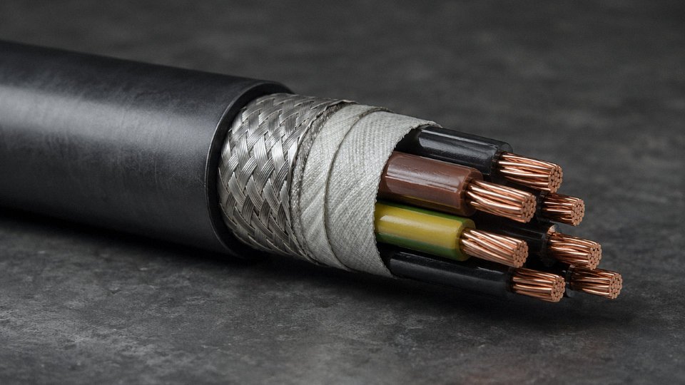
Anti-torsion braid layers, typically a textile or aramid braid over the conductor bundle, are used in robotic and festoon cable designs to mechanically limit torsional displacement and prevent the bundle geometry from collapsing under cyclic twist. Fiber-reinforced cores — a central tension member, often Kevlar or fiberglass — carry axial loads in vertical hanging or festoon applications, preventing the conductors from taking tensile stress they weren’t designed for. These aren’t standard Class 5 features; they’re add-on constructions layered onto a Class 5 conductor foundation for high-demand installations.
Primary Application Sectors: Where Class 5 Cables Are Specified and Why
The question of where Class 5 cables get specified isn’t just academic — use the wrong flexibility class and you’re looking at conductor fatigue failures, nuisance tripping, or at worst, a cable that fractures internally while still appearing intact from the outside. Rigid Class 2 conductors are fine in fixed installations. Put them somewhere that flexes repeatedly and you’re creating a maintenance problem on a slow fuse.
Industrial Automation and Robotics
This is probably the highest-stakes application area for Class 5. Servo motor cables on articulated robot arms, drag chain cables running back and forth inside cable carriers, teach pendants that operators swing around all shift — these see anywhere from a few hundred thousand to several million flex cycles over a service life, depending on cycle rate and installation geometry. The fine-wire stranding of Class 5 distributes bending stress across a far larger number of individual wires than Class 4 or Class 2 would, which is exactly why robot cable manufacturers won’t touch coarser stranding for these applications. A drag chain failure mid-shift on an automotive weld cell can idle a line for hours. In practice, engineers also need to look at the jacket and lay length, not just the conductor class — but getting the conductor wrong first is the most common procurement mistake.
Building Wiring With Frequent Connection Changes
Commercial construction sites, temporary power boards on multi-story builds, portable equipment hookups — these environments involve cables that get moved, re-routed, coiled, and generally abused on a regular basis. Class 5 flexible cords handle this far better than the semi-rigid alternatives. Extension cables and portable RCD units in the 1.5 mm² to 6 mm² range are almost universally Class 5 for this reason.
Renewable Energy
Solar tracker drive cables flex slowly but continuously, exposed to UV, thermal cycling from roughly -25°C to +90°C depending on climate, and occasional wind-induced vibration. Wind turbine nacelle-to-tower power cables see torsional stress as the nacelle yaws — sometimes several full rotations over a turbine’s life. Battery storage module interconnects in utility-scale systems face vibration from ventilation systems and thermal expansion stress at every charge-discharge cycle. Class 5 conductors absorb all of this more gracefully than coarser stranding would.
Marine and Offshore
Shipboard flexible cables almost always specify tinned copper conductors — the tin coating resists the salt-air corrosion that bare copper struggles with in marine environments. Dynamic subsea umbilicals (the shallower sections that move with surface vessels) rely on Class 5 stranding to handle the repeated catenary motion without progressive wire breakage. Portable equipment leads on offshore platforms need to tolerate both mechanical abuse and the chemical exposure from cleaning agents and hydrocarbon contamination.
Class 5 tinned copper conductors offer better corrosion resistance in marine environments than bare copper Class 5 conductors.True
Tin plating provides a protective barrier against salt-atmosphere oxidation and sulfide corrosion, which is why IEC and marine classification societies typically require tinned conductors in shipboard and offshore flexible cables.
Welding and Heavy Portable Equipment
Welding return cables are probably the most physically punishing application in this list. They get coiled, dragged, kinked, stood on, and run across hot metal surfaces. Class 5 stranding — often going well above the IEC minimum wire count for conductors in the 35 mm² to 95 mm² range — gives these cables the flexibility to survive that treatment through a reasonable service life. Temporary generator sets and portable compressor leads face similar handling, though usually at lighter cross-sections.
Transportation Infrastructure
Rail and metro rolling stock use Class 5 conductors in under-carriage power cables and interior control wiring where vibration and repeated articulation stress are unavoidable. EV charging cables are an increasingly important case: a public fast-charger cable in a busy location might see 30,000 to 50,000 plug-in cycles over its installed life, and the cable needs to stay manageable in both summer heat and winter cold. Airport ground support equipment — GPU cables, aircraft pre-conditioned air hose assemblies — involves constant coiling and dragging across tarmac.
Jinda’s product range addresses each of these sectors with application-specific insulation and jacket systems built on IEC 60228 Class 5 conductor cores — silicone or EPR jackets for welding and high-temperature environments, LSZH compounds for rail and building applications, and tinned-conductor variants for marine and offshore work. The conductor class is the foundation, but the surrounding materials are what make it suitable for the specific environment rather than just technically compliant.
Class 5 vs. Class 2 vs. Class 6: Choosing the Right Conductor Class for Your Project
Getting the conductor class wrong costs more than the cable itself. A single nuisance fault on a CNC machine tool — traced back to a fatigue-cracked conductor in a flexible conduit drop — can run up hours of unplanned downtime, diagnostic labor, and a rewire job that nobody budgeted for. The cable is the cheap part. The consequences are not.
How the Three Classes Actually Differ
The core distinction is wire count and individual wire diameter. Finer wires, more of them, equals more flexibility — and more cost. It is that direct a relationship.
| Property | Class 1 (solid) | Class 2 (stranded) | Class 5 (flexible) | Class 6 (extra-flexible) |
|---|---|---|---|---|
| Wire count (16 mm² example) | 1 | 7 minimum | 196 minimum | Higher than Class 5 |
| Max individual wire diameter | Solid | Relatively coarse | Finer limit per IEC 60228 | Finer still |
| Flexibility rating | Rigid | Semi-rigid | Flexible | Extra-flexible |
| Typical installation | Fixed conduit, buried | Fixed conduit, trunking | Panel wiring, machine drops, trailing | Welding leads, portable tools |
| Approximate cost index vs. Class 2 | ~0.85× | 1.0× (baseline) | 1.10–1.25× | 1.35–1.60× |
Cost index ranges depend heavily on copper price at time of order, insulation material, and order volume. The 10–25% premium for Class 5 over Class 2 compresses on large-volume contracts; it can widen on small spot buys or specialty insulations like silicone or XLPE.
Class 2: Solid Enough for Fixed Work, Wrong for Movement
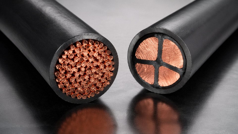
Class 2 stranded conductors are perfectly adequate — genuinely the right choice — for fixed wiring in conduit, trunking, or direct burial where the cable goes in once and stays there. The strand count is a fraction of what Class 5 delivers at the same cross-section. Seven wires at 16 mm² versus 196. That lower wire count keeps the conductor stiffer, which is fine when nothing moves, but each individual wire carries a higher proportion of the mechanical bending stress when the cable flexes repeatedly.
In practice, Class 2 conductors installed in flexible conduit drops on machine tools — a surprisingly common substitution when someone is trying to stretch a cable budget — tend to show fatigue cracking within three to eighteen months depending on bend radius and cycle frequency. The failure mode is insidious: individual strands break progressively, resistance climbs, the circuit develops intermittent faults, and the diagnostic trail is frustrating because nothing looks obviously wrong until you cut the conductor open.
Class 6: When Class 5 Is Not Enough
Class 6 uses finer individual wires than Class 5 — the IEC 60228 wire diameter limits are tighter — producing a noticeably softer, more supple cable. Welding leads, hand-held power tools, and trailing cables on port equipment that flex constantly under tension are the genuine use cases. The construction is more labor-intensive to manufacture and harder to terminate cleanly with standard ferrules; the wires are fine enough that a poorly crimped end-sleeve can shear a meaningful number of strands.
For standard panel wiring and machine connection boxes, Class 6 is over-engineering. You pay the premium — roughly 35–60% above Class 2 baseline, depending on cross-section and insulation — without gaining anything operationally useful. The cable is harder to route neatly and the fine strands tend to splay during termination if the installer is not careful.
A Decision Framework That Actually Works
Fixed installation in conduit or trunking, no movement after commissioning: specify Class 2. It is cheaper, easier to source in bulk, and termination is straightforward.
Flexible connections — panel wiring, junction box tails, machine tool drops, servo motor feeds — where the cable moves during installation or sees occasional repositioning: Class 5 is the correct specification. The 10–25% material premium over Class 2 is recovered quickly once you account for avoided rewiring and fault-finding labor. On a machine tool with a six-axis arm, a single unplanned fault investigation by an electrician can cost more than the entire cable bundle.
Continuous heavy mechanical flexing, abrasion exposure, or welding service: Class 6.
Substituting Class 2 stranded conductors for Class 5 in dynamic machine tool connections is a code-compliant error in many jurisdictions — the cable may pass inspection at installation but fail IEC 60228 intent for the application.True
IEC 60228 defines conductor classes by flexibility requirement. Specifying Class 2 where movement is present may satisfy a loose visual inspection but does not meet the standard's intended application criteria, and fatigue failure risk is demonstrably higher based on wire count and individual wire stress distribution.
The substitution usually happens under procurement pressure or because Class 5 stock was unavailable at short notice. Getting the class right at the specification stage — before the purchase order — is far cheaper than correcting it after commissioning.
International Standards, Certification Marks, and Procurement Compliance for Class 5 Cables
The standard that anchors everything is IEC 60228 Third Edition (2004) — “Conductors of insulated cables.” It defines Class 5 as the flexible conductor class for fixed or mobile installation, sets maximum DC resistance values per cross-section, and caps individual wire diameters to force the fine-strand geometry that gives Class 5 its mechanical character. Every credible supplier and every serious tender document should reference this edition specifically. The 1993 second edition is still cited in some older project specs; if you see that, push the supplier to confirm their product meets the 2004 requirements, because the third edition tightened several resistance limits and clarified bundle construction rules.
National standards largely harmonize with IEC 60228 rather than diverging from it, though the naming differs. BS 6360 in the UK maps directly; VDE 0295 in Germany aligns class-for-class; GB/T 3956 in China is the national equivalent and is structurally identical for Class 5. In practice, a conductor that passes GB/T 3956 Class 5 will also satisfy IEC 60228 Class 5 requirements, assuming the test methods followed the standard correctly — which is exactly why you want to see the actual test certificate, not just a declaration.
Product-Level Standards That Invoke Class 5
IEC 60228 covers conductors only. The cable as a whole — insulation, sheathing, voltage rating — is governed by separate product standards, all of which reference IEC 60228 for conductor class specification. IEC 60227 covers PVC-insulated cables to 450/750 V, the workhorse category for most industrial flexible cord. IEC 60245 covers rubber-insulated cables, which is where welding cables and portable equipment cables live. IEC 62893 governs EV charging cables, a rapidly growing procurement category where Class 5 or Class 6 conductors are essentially mandatory given the repeated flexing during plug-in cycles. IEC 60092 applies to shipboard installations, where a combination of vibration, salt air, and confined routing makes conductor flexibility critical. If you’re sourcing cable for any of these applications, the drum label should ideally cite both the product standard and IEC 60228 Class 5. A label citing only IEC 60227 without the conductor class declaration is incomplete — not necessarily non-compliant, but worth querying.
Certification Marks and What They Actually Tell You
Marks vary by market and mean slightly different things. VDE certification (Germany’s VDE Institut) involves third-party factory audits and product testing; a VDE mark on the drum means an independent body has verified production samples, not just that the manufacturer self-declared. BSI Kitemark (UK) works similarly. KEMA-KEUR is the Dutch certification mark and carries equivalent weight in European industrial procurement. CE marking under the Low Voltage Directive is legally required for the EU market but is self-declaration — it signals regulatory awareness, not independent audit. UL Listed applies to the North American market, but be aware that UL uses its own stranding classification system that doesn’t map one-to-one onto IEC classes; a UL-rated flexible cord isn’t automatically IEC 60228 Class 5 compliant without separate verification. CCC (China Compulsory Certification) is required for certain cable categories sold in the Chinese domestic market and involves CNAS-accredited lab testing.
Verifying Compliance When the Delivery Arrives
This is where procurement discipline matters most. Check the drum label for an explicit “IEC 60228 Class 5” declaration — not just a conductor size. Request the manufacturer’s test certificate showing DC resistance per meter run, individual wire diameter measurements, and wire count for the relevant cross-section. On large shipments, an incoming inspection resistance check with a calibrated micro-ohmmeter costs almost nothing and will catch a surprising number of substitutions, particularly on spot-buy cables from unfamiliar sources.
For infrastructure projects — power plant fit-outs, port equipment, large data centers — third-party laboratory testing is worth the cost. CNAS-accredited labs in China and ILAC-member labs internationally can perform full IEC 60228 conductor resistance verification, wire count, and dimensional checks. The test fee on a $200,000 cable order is negligible compared to the cost of discovering a non-conformance after installation.
Cables labeled 'flexible' or 'multi-strand' are not necessarily IEC 60228 Class 5 compliantTrue
IEC 60228 Class 5 requires specific minimum wire counts and maximum individual wire diameters per cross-section. A cable can have multiple strands and still only meet Class 2 or Class 4 requirements if the strand count or diameter limits don't match the standard's tables.
Jinda’s Quality Documentation as Standard Practice
Jinda’s production process includes drum-by-drum DC resistance testing using in-house metrology equipment traceable to national standards, with mill certificates issued as a standard deliverable on every shipment — not an optional add-on that requires a special request. For international tender projects, that documentation typically covers IEC 60228 Class 5 compliance, GB/T 3956 test records, and dimensional inspection data. It’s the kind of paper trail that procurement engineers need when submitting to owner’s engineers or third-party commissioning inspectors, and it’s considerably easier to specify upfront than to chase retrospectively once cables are on-site.
Specifying Class 5 Cables in Purchase Orders: Cross-Section, Length, Drum Size, and Documentation
A purchase order that simply says “flexible cable, 2.5 mm², 100 meters” will get you something. Whether it’s the right something is another matter. Disputes over conductor class, insulation grade, and drum length make up a disproportionate share of delivery problems in cable procurement — and nearly all of them trace back to an underspecified order.
The Minimum Specification String
Every Class 5 cable order should include, in sequence: conductor cross-section in mm², number of cores, explicit conductor class reference (IEC 60228 Class 5 annealed copper), insulation material and voltage rating, jacket material, and the relevant product standard. Skipping any one of those fields creates a gap a supplier can fill with whatever they have in stock.
A workable example string looks like this:
3 × 2.5 mm² + E 1.5 mm², IEC 60228 Class 5 annealed copper, PVC insulation 300/500 V to IEC 60227-5 (H05VV-F), grey PVC outer sheath, drum length 100 m
The “+ E 1.5 mm²” designation calls out an earth conductor — worth being explicit about, because some suppliers default to a reduced earth cross-section unless told otherwise. The H05VV-F designation ties the whole assembly to a harmonized product standard, which in turn locks in flame-test requirements, insulation thickness, and a dozen other parameters you’d otherwise have to list individually.
Drum Lengths and Cut-to-Length Tolerances
Standard catalog lengths run at 50 m, 100 m, 200 m, 500 m, and 1,000 m on plastic or wooden drums. Most manufacturers keep 100 m and 500 m reels in common sizes (0.5 mm² through 35 mm²) as running stock. Above 95 mm² or 120 mm², you’re usually looking at made-to-order drum builds, and the reel itself gets heavy enough that wooden drums become the norm for sea freight.
Cut-to-length tolerance of ±0.5% is the accepted industry default — so a 500 m order might deliver 497.5 m to 502.5 m and that’s compliant. If your project has a hard minimum (a long cable tray run where you can’t splice), call out “minimum 500 m, no negative tolerance” explicitly. Tighter tolerances than ±0.5% are achievable but almost always cost more and slow production slightly, so only specify them when genuinely necessary.
How Cross-Section Tolerance Actually Works
A cable labeled 2.5 mm² must measure exactly 2.5 mm² in actual cross-section to comply with IEC 60228.False
IEC 60228 does not directly specify a nominal cross-section dimensional tolerance. Compliance is verified through the DC resistance limit — for a Class 5 conductor at 2.5 mm², that limit is ≤7.41 Ω/km at 20°C. A conductor measuring roughly 2.3 mm² actual cross-section can still be fully compliant if its resistance stays within that limit, because higher-conductivity copper or tighter stranding geometry can compensate.
This matters when you’re receiving inspection. Measuring physical diameter and calculating geometric cross-section will often give you a number that looks undersized. The correct acceptance test is resistance measurement against IEC 60228 Table 4, not a caliper check. Insisting on both a conductor test certificate and raw resistance values per drum is the cleanest way to verify compliance without ambiguity.
Documentation Package
Request this as a standard package with every order: IEC 60228 conductor test certificate (per production lot, not a generic factory certificate), material safety data sheet for the jacket compound (relevant for enclosed installation environments), country-of-origin certificate, packing list with individual drum serial numbers, and — for sea freight — an insurance certificate listing actual drum count and declared value. The drum serial number linkage is particularly useful if you receive a mixed shipment and need to trace a nonconformance back to a specific production run.
Lead Time Realities
Standard sizes in common insulation systems — roughly 0.5 mm² through 70 mm² in PVC or XLPE — typically ship from stock within 2 to 4 weeks, depending on order volume and the supplier’s inventory position at the time. Non-standard insulation systems (silicone, TPU, halogen-free LSOH compounds) or large cross-sections above 185 mm² usually need 8 to 12 weeks of production lead time, sometimes longer if the stranding equipment is scheduled for other work. Seasonal effects are real: Q4 order surges and Chinese New Year factory closures can push even standard-size lead times out by two to four weeks. Build that buffer into your project schedule rather than treating the catalog lead time as a guarantee.
Installation Best Practices for Class 5 Flexible Cables in Dynamic and Static Service
Getting the specification right on paper means nothing if the cable is installed badly. Class 5 fine-stranded conductors are engineered for flexibility, but that advantage disappears fast when routing radii are too tight, ferrules are skipped, or cable ties are torqued down by someone in a hurry.
Minimum Bending Radius — and Why It Actually Matters
For cables running in cable carriers (energy chains), maintain a moving bend radius of at least 6× the cable’s outer diameter. In practice, most carrier manufacturers recommend 7–10× OD for their own warranty coverage, so 6× is a floor, not a target. For static flexible drops — pendant cables, machine pigtails, door-hinge loops — 4× OD is generally acceptable under IEC 60364 interpretations, because the bend isn’t cycling. Violate either limit consistently and you’ll see individual wire strands fracturing at the bend apex, usually within months rather than years. The failure is insidious: resistance creeps up, the cable runs warm, insulation degrades, and eventually a strand breaks through the jacket. By then the root cause is long gone.
Termination: Ferrules Are Not Optional
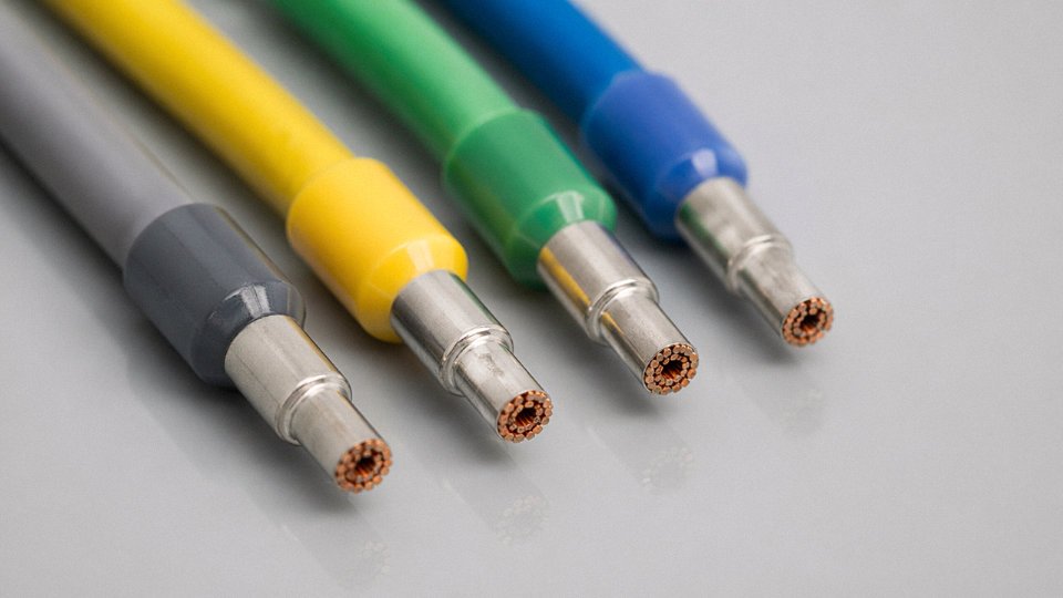
This one causes more field failures than almost anything else. Class 5 conductors — say, a 2.5 mm² core with 50-odd fine wires — will fan out under a screw terminal and cold-flow over time, creating a loose, high-resistance joint that arcs under load. Ferrules (wire end sleeves, DIN 46228) are mandatory at every screw-clamp terminal. Use insulated ferrules for control wiring, uninsulated where the terminal manufacturer specifies. Match the ferrule cross-section exactly to the conductor; an oversized ferrule crimped onto fine stranding is almost as bad as no ferrule at all.
For ring or fork lugs, use a crimp die specifically rated for fine-stranded conductors. A die sized for Class 2 solid-stranded wire will under-compress the bundle, leaving voids that corrode and loosen. Stab-in (push-in) terminals are fine only if the terminal datasheet explicitly states compatibility with fine stranding — check that before assuming.
Ferrules are mandatory for Class 5 fine-stranded conductors at screw terminalsTrue
Fine-stranded Class 5 conductors fan under screw clamp pressure and cold-flow over time, creating resistance rise and potential arc faults. IEC 60947-7-1 and terminal manufacturers' own installation guides consistently require wire end sleeves (ferrules per DIN 46228) for this conductor class.
Cable Glands and Strain Relief
The conductor should never carry tensile load. At every panel entry, enclosure wall, or junction box, fit a correctly sized cable gland with integral strain relief — the jacket grips the gland, the gland grips the enclosure, and the conductor sees zero axial pull. This sounds obvious but gets ignored on retrofit work constantly. An undersized gland that grips the outer jacket on only 3–4 mm of contact will creep loose inside six months of vibration.
Cable Carrier Installation Details
Lay the cable flat in the carrier tray without twisting its axis — even a quarter-turn of rotation at installation introduces torsional stress that accumulates with every carrier cycle. Allow roughly 2–3% sag in the unsupported span; too taut and the cable stretches under dynamic load, too loose and it slaps the carrier walls. When multiple cables share a carrier, fit separators. Adjacent cables abrading each other through 10 million cycles will breach jacketing even on reasonably rugged materials. Igus and similar carrier suppliers publish fill ratio guidelines; stay under 60% of the carrier cross-section as a working rule.
Panel Routing and EMI
In control panels, keep Class 5 power leads — especially servo drive cables — segregated from signal and fieldbus wiring. Use flexible conduit or spiral wrap where power leads must pass near signal cables or cross sharp panel edges. The spiral wrap does double duty: it reduces electromagnetic coupling and protects the jacket from abrasion that panel sheet-metal edges cause over time, particularly when the panel vibrates on a machine base.
Common Errors Worth Calling Out
Over-tightening cable ties is endemic on plant floors. A tie cranked down hard on a fine-stranded cable creates a stress concentration point; under cyclic bending, that’s where the strands break first. Finger-tight plus one click is usually enough. Routing Class 5 cables near exhaust manifolds, hydraulic oil coolers, or brake resistors is another recurring mistake — the insulation temperature rating (often 70°C or 90°C) gets exceeded locally, the plasticizer migrates out of the PVC jacket, and it goes brittle in under a year. Leave thermal clearance or fit a heat shield. Neither is expensive. Replacing a cable routed through a machine frame mid-production run is.
Frequently Asked Questions About Class 5 Cables
Is Class 5 cable the same as flexible cable?
Not exactly, and this distinction matters when you’re writing a spec or reviewing a supplier’s datasheet. Class 5 defines conductor construction — specifically, the fine stranding geometry and wire diameter limits set out in IEC 60228. “Flexible cable” is a broader commercial and product category that describes a cable’s overall design intent, which can encompass jacket material, sheath flexibility, and bending radius. Every Class 5 conductor is flexible by nature, but a cable marketed simply as “flexible” on a drum label or product listing hasn’t necessarily told you anything about its conductor class. You need the supplier to explicitly declare IEC 60228 Class 5 — not just use the word flexible as marketing language. In practice, I’ve seen cables sold as flexible control cables that turned out to have Class 2 stranded conductors inside, which will fail early in any application with real movement.
Can I use Class 5 cable for fixed wiring instead of Class 2?
Yes, and there’s no electrical penalty for doing so. The DC resistance limits in IEC 60228 Table 4 are identical for Class 5 and Class 2 at the same cross-section, so voltage drop calculations and current-carrying capacity assessments carry over directly. The honest reason Class 2 dominates fixed-installation work is cost — fewer, thicker wires mean less copper drawing time and lower manufacturing overhead, so Class 2 tends to run cheaper per metre, especially in larger cross-sections. If you already have Class 5 cable on site and need to run a fixed circuit, use it without hesitation. Just don’t specify it universally for an entire building wiring project when nobody needs the flexibility, because the cost difference across thousands of metres adds up.
What is the difference between Class 5 and Class 6?
Both classes are flexible, but Class 6 takes fine stranding further — higher minimum wire counts, smaller individual wire diameters, and correspondingly greater bend endurance. IEC 60228 positions Class 6 for extreme-duty portable applications: welding cables, portable tools, and trailing leads that get coiled, dragged, and flexed thousands of times daily. Class 5 covers general flexible service, which is the vast majority of industrial and machine wiring. Class 6 costs more and the finer stranding can complicate termination. Unless your application genuinely involves continuous or very high-cycle flexing — a welding torch lead, a festoon cable on a crane runway — Class 5 is usually the right answer, and specifying Class 6 everywhere is over-engineering that adds cost without measurable benefit.
Does Class 5 cable require special connectors or terminals?
This is the most frequently ignored installation issue with fine-stranded conductors, and it causes real problems. Fine wires in a Class 5 conductor will not clamp securely in a standard screw-clamp terminal block — individual strands splay out, some miss the clamping zone entirely, and under vibration or thermal cycling the joint loosens. The correct approach is to fit a DIN 46228 wire end ferrule (often called an end sleeve or bootlace ferrule) before inserting the conductor into any screw terminal not explicitly rated for fine stranding. Spring-cage terminals from some manufacturers handle fine stranding reasonably well without ferrules, but verify the terminal datasheet before assuming that. Loose strands bridging adjacent terminals in a control cabinet are a short-circuit hazard and, in low-voltage signal circuits, a source of intermittent faults that can take hours to trace.
How do I confirm that a drum delivered to site contains genuine Class 5 conductors?
Three steps, in order of effort. First, read the drum label — it should state IEC 60228 Class 5 explicitly, not just a wire count or the word flexible. Second, request the factory DC resistance test certificate for that specific drum lot and check the measured value against IEC 60228 Table 4 limits for the declared cross-section; a 1.5 mm² Class 5 copper conductor should read ≤ 13.3 Ω/km at 20 °C. Third, if you want physical verification, a four-terminal Kelvin milliohmmeter connected across the full drum length (with drum length taken from the label) gives you a direct check against that same limit. This takes roughly ten minutes and has caught substituted Class 2 conductors supplied under a Class 5 order more than once on large projects.
The DC resistance limit for a 1.5 mm² Class 5 flexible copper conductor is ≤13.3 Ω/km at 20°C per IEC 60228 Table 4.True
IEC 60228:2004 Table 4 specifies maximum DC resistance values for Class 5 and Class 6 flexible conductors; the value for 1.5 mm² plain or tinned copper is 13.3 Ω/km at 20°C, identical to Class 2 for the same cross-section.
What cross-sections does Class 5 cover, and is there a maximum?
IEC 60228 Class 5 runs from 0.5 mm² at the small end up to 630 mm² at the large end, covering everything from fine control wiring through medium-voltage power conductors. Above 630 mm², IEC 60228 simply doesn’t define a class — conductor construction at those sizes is typically agreed directly between the manufacturer and the purchaser, referenced against project-specific or national standards. For most industrial procurement, 630 mm² is a practical ceiling anyway; flexible conductors at that cross-section are heavy, stiff by any reasonable definition, and usually only appear in shipboard or large mobile machinery applications.
Are Class 5 cables suitable for VFD output circuits?
The conductor class itself isn’t the limiting factor here. Class 5 copper conductors are electrically fine for variable-frequency drive output wiring — the resistance and current-carrying capacity are identical to any other copper conductor of the same cross-section. What actually governs cable selection on VFD output circuits is insulation system and shielding. PWM switching at typical VFD carrier frequencies generates voltage pulses with fast rise times and significant high-frequency common-mode noise. PVC insulation rated to standard 300/500 V or 450/750 V is borderline at best for drives operating above 480 V; XLPE or EPR insulation with higher impulse withstand strength is a safer choice. A braided or foil-plus-drain-wire shield is essentially mandatory on runs longer than a few metres to keep common-mode noise off adjacent signal cables. So specify Class 5, yes — but treat insulation grade and shielding as the primary selection criteria for VFD wiring, and don’t let conductor class dominate that conversation.