Cables buried in the 1990s failing ahead of schedule, unplanned outages eating into production hours, and a replacement dig costing three to five times what a properly specified installation would have — this is the pattern that shows up when armored cable selection gets treated as a commodity decision. Moisture ingress, incorrect burial depth, mechanical overloading, and mismatched armor type for the environment all accelerate degradation faster than most maintenance teams expect, and by the time insulation resistance readings start dropping, the damage is well along.
Armored cable has a standard design lifespan of 25–40 years under normal operating conditions, per IEC 60502 and BS 6346 guidelines. Actual service life depends heavily on installation quality, burial depth, soil chemistry, operating temperature, and whether the armor type — SWA, STA, or AWA — matches the mechanical and chemical demands of the environment. Cables installed and maintained correctly routinely reach the upper end of that range; poorly installed cables can fail in under a decade.
What that range doesn’t tell you is where your specific installation sits inside it — and the gap between 25 years and 40 years is not a minor rounding difference, it’s a full infrastructure replacement cycle for many facilities. The factors that push a cable toward one end or the other are mostly controllable at the design and procurement stage, which is exactly what the rest of this guide works through.
Armor Construction Types and Their Direct Impact on Cable Longevity
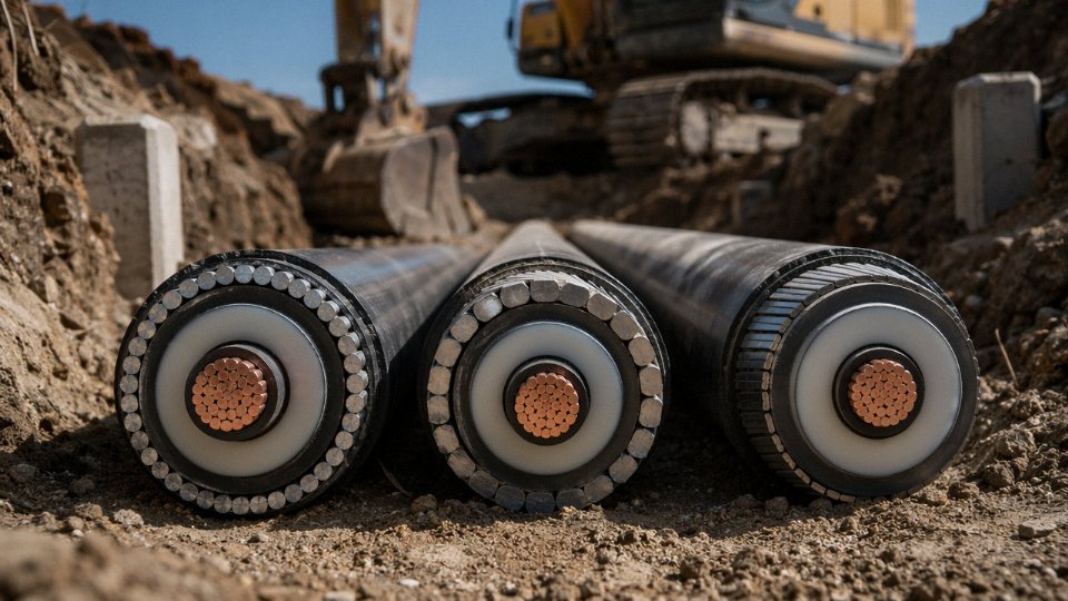
The armor layer is not decoration. It’s the primary mechanical barrier between your conductor system and whatever the installation environment throws at it — and the construction type you specify at procurement will shape maintenance intervals, failure modes, and ultimately how close to that 25–40 year design life the cable actually gets.
Steel Wire Armored (SWA)
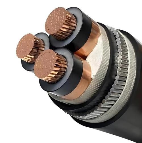
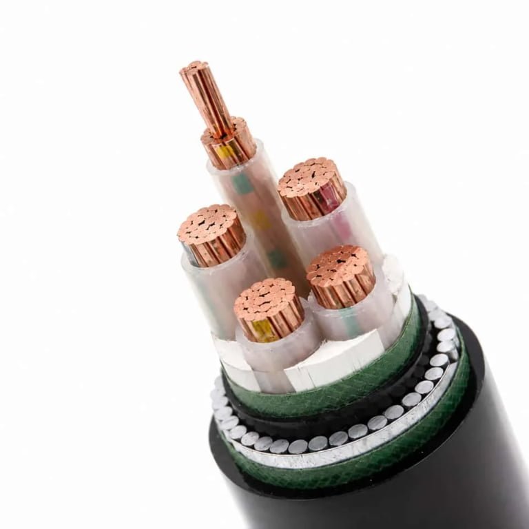
SWA is the workhorse. Round galvanized steel wires — typically drawn to tensile strengths in the 540–690 MPa range per IEC 60502, though the exact figure depends on wire diameter and grade — are laid helically over the inner sheath, and that geometry is what gives the cable its combined tensile and crush resistance. The lay angle matters more than most specs sheets acknowledge: a tighter helix improves longitudinal pull resistance, which is critical for cables installed on vertical runs or pulled through long conduit bends.
In direct burial applications, the galvanizing buys you meaningful corrosion resistance — typically 15–25 years before zinc depletion becomes a measurable concern, assuming neutral soil pH and reasonable drainage. Push the soil conductivity up (salty coastal fill, contaminated industrial ground) and that timeline compresses. In practice, most premature SWA failures I’ve seen in industrial facilities trace back not to the wire itself but to damaged end seals at termination glands — the armor corrodes from the cut end inward when moisture ingress is not properly managed.
For cable tray, conduit, and direct burial in standard industrial environments, SWA remains the default specification for good reason.
Steel Tape Armored (STA)
STA replaces the wire layer with one or two helically applied steel tapes. The geometry shifts performance: you get better radial crush resistance per unit weight than SWA, but you sacrifice tensile strength significantly. STA is not a substitute for SWA on any run with meaningful pulling tension or vertical routing.
Where STA earns its place is in static horizontal installations — think cable runs laid into concrete troughs in a substation or protected horizontal ducts — where the mechanical loading is primarily compressive and predictable. The trade-off to watch is corrosion. The tape edges are exposed at the overlap, and in high-moisture or acidic soil environments, undercutting corrosion progresses faster along the tape than on equivalent galvanized wire. In aggressive ground conditions, STA without additional oversheath protection can show measurable corrosion within 8–12 years, which effectively limits your service life well below the design target.
Aluminum Wire Armored (AWA)
AWA substitutes aluminum alloy wires for steel. The corrosion immunity in marine and coastal environments is the headline advantage — aluminum forms a stable oxide layer that holds up where galvanized steel eventually fails. Offshore platform cable runs, harbor installations, and coastal industrial facilities are the natural home for AWA.
The mechanical trade-off is real. Aluminum wire carries roughly 40–50% lower tensile strength than equivalent steel wire, which means AWA cables require more conservative pulling tension limits and are generally not recommended where significant mechanical abuse is expected. The weight reduction — typically 20–30% lighter than SWA of equivalent construction — matters on aerial and offshore installations where support structure loading is constrained.
AWA provides superior corrosion resistance compared to galvanized SWA in marine and high-chloride environmentsTrue
Aluminum's passive oxide layer resists chloride-driven corrosion far better than zinc-coated steel, making AWA the standard specification for offshore and coastal cable installations per IEC and industry practice.
One derating note: in single-core AC circuits, aluminum armor creates lower eddy current losses than steel armor — a genuine operating efficiency benefit, not just a weight story.
Double Steel Tape Armored (DSTA)
DSTA uses two steel tapes applied with opposing lay directions, so the overlaps are staggered. That geometry is the point. The overlapping tape layers distribute radial compressive loads more evenly around the cable circumference, which matters in environments where point loading is unpredictable — mine roadways, railway crossings, and anywhere heavy equipment might roll over the cable route.
The double-tape construction does not double your tensile strength, but it significantly improves resistance to sustained crush loading, and the staggered overlap reduces the risk of corrosion undercutting penetrating both layers simultaneously. In mining and rail applications where mechanical damage is the primary failure driver, DSTA can meaningfully extend service life compared to single STA — though the protection is only as good as the outer sheath integrity above it.
Comparative Summary
| Armor Type | Tensile Strength | Corrosion Risk | Recommended Environment | Typical Design Life Range |
|---|---|---|---|---|
| SWA | High (540–690 MPa) | Moderate (depends on soil pH, zinc depletion rate) | Direct burial, cable tray, industrial facilities | 25–40 years |
| STA | Low–Moderate | Higher in wet or acidic soil; tape edges vulnerable | Static horizontal runs, protected ducts | 20–35 years |
| AWA | Moderate (lower than SWA) | Low in marine/coastal environments | Offshore, aerial, coastal installations | 25–40 years in suitable environments |
| DSTA | Moderate radial, lower tensile | Similar to STA; mitigated by overlap geometry | Mining roadways, rail crossings, high-crush zones | 25–35 years with intact oversheath |
Design life ranges assume correct installation depth — 0.5 m minimum for LV, 0.9–1.2 m for HV per IEC and NEC Article 300 — appropriate gland sealing, and no sustained overloading. Change any of those inputs and the numbers shift accordingly.
How Insulation and Sheath Materials Age — And When They Fail
Armor gets the attention. It’s visible, measurable, and satisfying to specify. But in most field failures I’ve seen, the armor is still intact when the cable is pulled — it’s what’s inside that gave up first. Insulation degradation is the binding constraint on actual service life far more often than mechanical damage, and understanding the mechanisms helps you predict failure rather than just react to it.
XLPE: Water Treeing and Voltage Stress
Cross-linked polyethylene is the dominant insulation choice for medium-voltage armored cables, and for good reason — it handles operating temperatures up to 90°C continuously and has excellent dielectric properties when new. The problem shows up 15–20 years into wet burial. Water trees are electrochemical degradation channels that grow from microscopic voids or contaminants in the insulation toward the conductor, driven by voltage stress concentration. They don’t cause immediate failure; they increase dielectric loss gradually until partial discharge activity accelerates the process into electrical treeing, which does fail catastrophically.
This is why MV armored cables in direct-burial or duct-in-wet-ground installations should be on a tan-delta (dissipation factor) diagnostic testing schedule by roughly year 18–20. Tan-delta trending over two or three test cycles gives you a degradation curve — flat is fine, rising sharply means plan a replacement window before it becomes an emergency outage. Skipping this step is how a 25-year-old cable fails at 3 AM on a Sunday.
XLPE-insulated MV cables in wet burial applications commonly exhibit measurable water treeing after 15–20 years of serviceTrue
Water treeing in XLPE insulation under sustained voltage stress and moisture ingress is a well-documented phenomenon confirmed by IEC technical reports and utility maintenance data; it is the primary reason tan-delta testing is recommended for aging MV cable circuits.
PVC Insulation: Plasticizer Migration and Why It’s Fading Out
PVC insulation ages primarily through plasticizer migration — the chemical additives that keep it flexible slowly diffuse out over time, especially at elevated temperatures. At rated operating temperature, embrittlement typically sets in over 20–30 years, with the timeline compressing significantly in cables that routinely run warm. A PVC-insulated SWA cable that spent 15 years in a poorly ventilated cable tray carrying near-full load may be mechanically brittle before its 20th birthday.
This is why PVC-insulated SWA is rarely specified for new industrial projects above 1 kV today. It’s still common in LV distribution and legacy replacement work, but engineers writing specs for new MV infrastructure generally move straight to XLPE.
EPR: The Right Choice When Conditions Are Brutal
Ethylene propylene rubber maintains flexibility and dielectric performance at 90°C continuous, handles intermittent overloads better than XLPE in most practical installations, and — critically — it doesn’t water-tree in the same way. In marine, mining, and flexible trailing cable applications, EPR is often the only sensible choice despite costing 20–40% more than comparable XLPE constructions depending on conductor size and voltage class. The flexibility retention alone reduces termination fatigue failures in trailing cables dramatically.
Outer Sheaths: UV, Cold, and Confined-Space Chemistry
The outer sheath is the cable’s interface with its environment, and the degradation modes vary sharply by installation type. Standard black PVC sheaths handle UV reasonably well in above-ground runs, but in high-UV environments — unshaded outdoor cable bridges in equatorial climates, for instance — surface cracking appears in 8–12 years and eventually allows moisture ingress behind the armor. Below -15°C, standard PVC becomes brittle enough that ordinary handling during winter maintenance can crack it. For cold climates, a polyethylene or cold-rated PVC compound is necessary.
In tunnels, underground transit infrastructure, and confined cable rooms, LSZH (low-smoke zero-halogen) sheathing matters for two reasons: safety in a fire event, and protection of adjacent cables. A burning PVC sheath releases hydrochloric acid vapor that attacks the insulation on neighboring cables — a cascade failure mode that’s made more expensive by the fact that the undamaged cables are often blamed until the root cause is traced.
The Arrhenius Factor: Why Conductor Sizing Affects Lifespan Directly
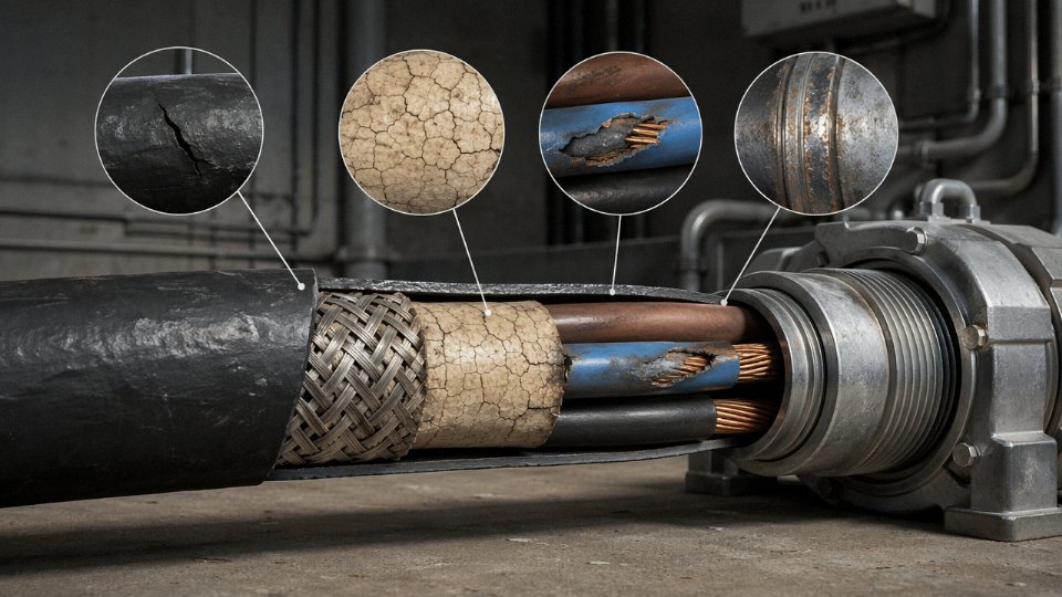
Thermal aging in polymer insulation follows Arrhenius kinetics. In plain terms: roughly every 10°C rise above the insulation’s rated continuous operating temperature halves its service life. A XLPE cable rated at 90°C that routinely operates at 100°C doesn’t last a bit less — it lasts approximately half as long. Run it at 110°C and you’re looking at a quarter of the design life.
This makes conductor sizing and load management a direct lifespan variable, not just an efficiency consideration. Undersized conductors running near thermal limit in a warm ambient — a cable tray in a boiler room, a duct bank with poor heat dissipation — can reduce a nominally 30-year cable to a 12–15 year cable with no visible external change until something fails. Checking actual operating temperatures against nameplate ratings during commissioning, and again after any load growth, is basic maintenance discipline that most plants I’ve visited only do after their first premature cable failure.
Installation Environment Factors That Shorten or Extend Service Life
The armor layer on a cable is not self-sufficient. Put the wrong cable in the wrong ground, and you can cut a 35-year design life down to 12. Environment is often the deciding variable — more so than the cable construction itself.
Soil Corrosivity
Soil resistivity is the number most procurement engineers never ask for, and it’s the one that matters most for direct-burial SWA installations. ASTM G57 gives the field measurement method; the critical threshold is roughly 1,000 ohm-cm. Below that figure — which is typical of wet clay, coastal reclaimed land, and soils contaminated by industrial runoff — galvanized steel wire armor will corrode progressively. In practice, you’re looking at 10 to 15 years before armor integrity is compromised in highly corrosive soils, compared to 30-plus years in well-drained sandy or rocky ground with resistivity above 5,000 ohm-cm.
The fix is not always cathodic protection, which is expensive to maintain and frankly overkill for most LV distribution runs. A properly specified PVC oversheath — minimum 1.8 mm thick, continuous without pin-holes — usually breaks the electrochemical circuit effectively enough for soils in the 500–1,000 ohm-cm range. Below 500 ohm-cm, in genuinely aggressive coastal or industrial-contaminated ground, you should be specifying double-sheathed construction or considering aluminum wire armor, which forms a passive oxide layer and outperforms galvanized steel in chloride-rich environments.
Moisture and Groundwater
Waterlogged trenches create a two-pronged attack: hydrostatic pressure works mechanical fatigue on the armor wires over seasonal ground-movement cycles, while dissolved salts and oxygen drive galvanic corrosion. IEC 60332 water-penetration test criteria define the benchmark for what a cable should survive, but passing a type-test in a lab and spending 25 years below a fluctuating water table are different propositions entirely.
For any direct burial below the seasonal water table — and especially in flood-prone industrial zones — longitudinally water-blocked armored cable is the right specification, not an upgrade. The water-blocking tape between the armor and the inner assembly prevents capillary migration along the cable core in the event of a sheath breach. Without it, a single mechanical nick from a later excavation can introduce moisture that tracks meters along the cable interior before symptoms appear at the termination.
Temperature Extremes
XLPE insulation rated at 90°C has a design life built around that continuous operating temperature. The Arrhenius degradation model is unforgiving: sustained operation at 100°C — just 10°C over rating, which happens routinely in undersized conduits or cables sharing a tight tray with other heat sources — roughly halves the insulation life. A cable that should last 40 years in a properly loaded, well-ventilated installation may realistically reach end-of-insulation-life in 18 to 22 years under those conditions.
Cold climates carry the opposite risk during installation rather than operation. Most SWA cables with PVC inner sheaths have a minimum installation temperature of around -5°C to 0°C; pull a stiff cable around a bend at -15°C and the PVC bedding can crack. That damage is invisible and cumulative. IEC 60502 bending temperature limits exist for a reason — they tend to get ignored on winter construction sites when the schedule is tight.
Chemical and Industrial Atmospheres
Standard PVC outer sheaths handle mild hydrocarbon splash and occasional cleaning-agent exposure adequately. They do not hold up well against continuous immersion in petroleum-based fluids, concentrated sulfur compounds common in wastewater treatment and petrochemical plants, or strong alkaline cleaners used in food-processing facilities. In those environments, PVC softens and loses its barrier function over 5 to 8 years rather than 25.
Polyurethane jackets offer meaningfully better resistance to aliphatic hydrocarbons and mechanical abrasion. HDPE outer sheaths are the right call in alkaline and acidic soil conditions where PVC would degrade — HDPE’s chemical inertness is well established and it doesn’t plasticizer-leach the way PVC does over decades underground.
| Chemical Environment | Standard PVC Sheath | Polyurethane Jacket | HDPE Outer Sheath |
|---|---|---|---|
| Petroleum hydrocarbons (surface) | Marginal | Good | Acceptable |
| Sulfur compounds / H₂S atmosphere | Poor | Acceptable | Good |
| Alkaline cleaning agents (pH >12) | Poor | Acceptable | Good |
| Mild acids (pH 4–6, soil) | Acceptable | Acceptable | Good |
| UV exposure, above-ground runs | Poor (degrades 5–10 yr) | Good | Good |
Mechanical Stress During and After Installation
This one tends to get overlooked because the damage isn’t visible and the consequences don’t show up immediately. The minimum bend radius for SWA cable during installation is typically 12 times the overall cable diameter per IEC 60346 guidance — a 40 mm diameter cable needs a minimum 480 mm bend radius. In practice, cable pullers routinely force tighter bends at duct entries and cable tray corners, especially under time pressure.
Bend radius violations during SWA cable installation create stress concentrations in both the armor wires and the insulation beneath them, accelerating dielectric breakdown over a period of years rather than causing immediate failure.True
Exceeding minimum bend radius plastically deforms armor wires and introduces localized mechanical stress on the XLPE or PVC insulation beneath. This does not cause immediate electrical failure but reduces the effective insulation thickness and creates sites of elevated partial discharge activity that progressively degrade the insulation, typically becoming detectable within 5–15 years depending on voltage stress and thermal cycling.
The insidious part is that a cable passing post-installation insulation resistance tests immediately after commissioning can still have a significantly shortened service life because of installation-induced damage. Partial discharge testing at commissioning catches this more reliably than a simple megger test, particularly for medium-voltage installations.
Operating Load, Voltage Stress, and Electrical Parameters That Govern Long-Term Performance
Most cable failures that get attributed to “end of life” are actually the cumulative result of how the cable was operated — not simply how long it was in the ground. Physical installation gets most of the attention, but the electrical environment a cable sees every day does just as much damage over a 30-year service period.
Load Cycling Fatigue
Every time a cable heats up under load and cools down at night or during a shutdown, the copper conductor expands and contracts. Over years of daily cycling, this creates mechanical fatigue at conductor joints, compression lugs, and the points where armor wires are terminated into glands and cleats. The insulation interface is particularly vulnerable — XLPE and EPR both have different thermal expansion coefficients than the copper underneath, so the interface works like a slow-motion friction joint.
Cables running continuously at 90–100% of their rated current ampacity experience this cycling effect in a more compressed, aggressive way than cables loaded at 70–80%. At the higher loading band, conductor temperatures routinely approach 90°C (the XLPE continuous rating), and the amplitude of each thermal cycle is larger. In practice, cables in that upper loading band show measurable insulation degradation — tracked via dielectric loss angle (tan δ) trending — somewhere in the 15–20 year range, while cables operated at the 70–80% band often reach 30+ years before any detectable change. The exact crossover depends on the number of daily cycles, ambient temperature, and burial or tray conditions.
Harmonic Distortion and Neutral Conductor Overheating
Variable frequency drives (VFDs) are everywhere now, and they introduce third-order harmonics that behave differently from the fundamental current. In a balanced three-phase system, fundamental and most harmonic currents cancel in the neutral. Third-order harmonics do not — they add arithmetically in the neutral conductor. For a multicore SWA cable feeding a VFD-heavy distribution board, the neutral core can carry 150–170% of the phase current even when the phases look balanced. That neutral is the same cross-section as the phases in most standard cables, so it runs hot. Localized neutral overheating accelerates insulation degradation in that core specifically, and because it’s buried in the middle of the cable assembly, it’s essentially invisible until something fails.
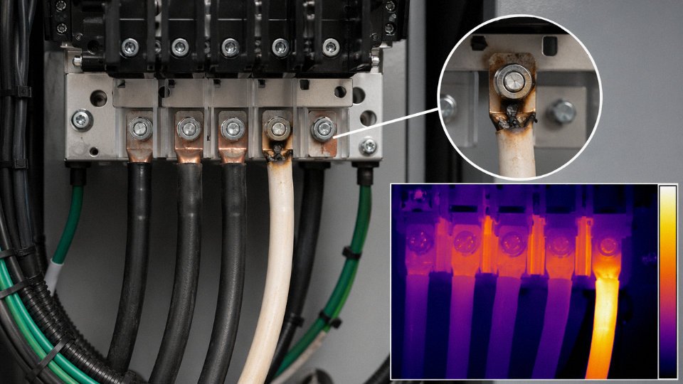
If your facility has a high VFD load density, specifying a cable with a full-sized or oversized neutral — or using a separate neutral conductor — is not over-engineering. It’s avoiding a premature failure that looks random when it isn’t.
Partial Discharge and Voltage Stress in MV Cables
For medium-voltage XLPE-armored cables, partial discharge (PD) is the slow killer that most plant engineers don’t think about until after an unexpected fault. PD initiates at microscopic voids, contaminants, or protrusions in the insulation — places where the local electric field exceeds the air’s breakdown strength. Each discharge event is tiny, but over years they erode the insulation wall from the inside.
IEC 60270 sets the acceptance threshold for MV XLPE cables typically below 10 pC at a test voltage of 1.5×U₀. Factory acceptance PD testing is genuinely a lifespan predictor, not a formality.
A cable that passes PD testing at 1.5×U₀ with readings below 10 pC is likely to achieve its rated 25–40 year design life, assuming correct installation and loadingTrue
IEC 60270 PD acceptance criteria are correlated with long-term insulation integrity in MV XLPE cables; cables with clean PD results at factory test statistically show lower in-service failure rates, per published utility data and IEC TR 62067 guidance
Always request factory test certificates with actual PD values, not just a pass/fail stamp. A reading of 8 pC and a reading of 3 pC are both “passes,” but they represent meaningfully different insulation quality.
Short-Circuit and Fault Current Exposure
A single through-fault event at roughly 10× rated current is enough to drive conductor temperature to around 250°C — the thermal withstand limit for XLPE per IEC 60949. At that temperature, the insulation doesn’t melt visibly, but the polymer cross-link structure degrades irreversibly. You can’t inspect your way out of it after the fact. The cable that survived the fault has a shortened remaining service life; by how much depends on the fault duration and how many such events have occurred. One severe fault can effectively age an XLPE cable by several years in a few seconds.
Upstream protection coordination matters to cable life in a way that often doesn’t appear in cable selection discussions. Undersized or slow-acting overcurrent protection that allows fault currents to linger for even fractions of a second beyond the cable’s thermal withstand time causes cumulative damage that only shows up years later as an unexplained insulation failure.
Power Factor, Reactive Loading, and Long Cable Runs
Lightly loaded cables on capacitive circuits — common in wind farm collector systems, offshore platform ring mains, and long underground feeders — operate at a higher voltage stress relative to the actual power being transferred. Poor power factor correction at the load end means the cable sees elevated voltage for extended periods without the corresponding thermal loading that would at least signal something is wrong. The aging mechanism here is purely electrical: voltage stress accelerates the PD initiation process described above, without the obvious warning of rising conductor temperature. For collector cables in wind farms, this is a real operational issue, particularly during low-generation periods when the cable is energized but lightly loaded.
Predictive Maintenance and Diagnostic Testing to Maximize Cable Service Life
Most armored cable failures don’t announce themselves — they build quietly over years through moisture ingress at a poorly sealed joint, a slow thermal degradation cycle, or a mechanical nick from a ground disturbance that nobody logged. The gap between a cable that lasts 25 years and one that reaches 38–40 years is almost entirely determined by whether anyone is actually monitoring it. Here’s how to do that competently.
Insulation Resistance Testing: Your Baseline Instrument
A Megger test is cheap, fast, and still the most widely used first-line diagnostic. For LV armored cables, apply 500 V DC; for MV cables, step up to 5 kV DC — using a lower voltage on MV insulation will simply miss the degradation you’re looking for. Run the test for 10 minutes and calculate the Polarization Index: PI = IR at 10 min ÷ IR at 1 min.
A Polarization Index above 2.0 is generally acceptable for XLPE-insulated armored cable, while a value below 1.0 indicates severe insulation degradation requiring immediate further investigation.True
The PI ratio method is a recognized diagnostic technique per IEEE Std 43 and is consistent with IEC testing guidance; the 2.0 threshold for XLPE reflects the material's relatively stable resistivity response, and values below 1.0 suggest contamination, moisture ingress, or carbonization.
In practice, you want a baseline reading taken within 48 hours of installation, before the cable goes into service. That baseline is what every future reading gets compared against — not some abstract table value. Schedule follow-up tests at roughly 5-year intervals under normal service, and immediately after any ground disturbance, flood event, or known fault.
Tan-Delta Testing: The MV Standard
For medium-voltage XLPE-armored cables, tan-delta (dissipation factor) testing is the most diagnostically informative test available. The methodology follows IEC 60060-3. Apply voltage at 0.5×U₀ and measure the dissipation factor — if tan-delta exceeds 0.004 at that stress level, you’re looking at water-tree degradation that has progressed far enough to begin replacement planning, not just monitoring. Values in the 0.001–0.003 range warrant increased frequency and trending. This test requires the cable to be de-energized, which is a real operational cost, but there’s no shortcut that gives you equivalent information.
TDR: Finding Problems Without Digging
Time-domain reflectometry sends a low-energy pulse down the cable and reads the reflections from impedance discontinuities — failed or degraded joints, water ingress points, crush damage. A competent TDR setup on a well-characterized route can locate faults to within 0.3–1.0 meters, depending on cable length and the quality of the velocity-of-propagation calibration. On long runs of 2–4 km, that resolution still spares you from excavating the wrong 100-meter stretch. Run TDR after any suspected mechanical event and as part of your 5-year inspection cycle.
DTS and Thermal Imaging
Distributed Temperature Sensing uses a fiber-optic element run alongside or bonded to the armored cable to give a continuous real-time temperature profile across the entire route. For 90°C-rated XLPE, set your alarm threshold at 85°C — that 5°C margin gives you time to react before insulation damage accumulates. Thermal imaging cameras are a reasonable alternative for exposed cable runs, switchgear, and terminations, though they won’t catch a buried hotspot.
Partial Discharge Monitoring: Long-Term Trending
Online PD monitoring attaches at cable terminations and records discharge activity while the circuit stays energized. A single PD snapshot tells you relatively little. What matters is the trend over 12–24 months — a steadily climbing PD magnitude indicates insulation deterioration that is accelerating, and that trend gives you a defensible remaining-life estimate to bring to capital planning discussions.
Recommended Maintenance Schedule
| Test Type | Recommended Interval | Acceptance Threshold | Standard Reference |
|---|---|---|---|
| Insulation Resistance (IR / PI) | Baseline at installation; every 5 years; post-event | PI ≥ 2.0 (XLPE); IR stable vs. baseline | IEEE Std 43; IEC 60502-2 |
| Tan-Delta | Every 5 years (MV cables) | Tan-delta < 0.004 at 0.5×U₀ | IEC 60060-3 |
| TDR | Every 5 years; post mechanical disturbance | No new reflections vs. baseline trace | IEEE 1617 |
| Distributed Temperature Sensing | Continuous (where DTS installed) | Alarm at 85°C for 90°C-rated XLPE | IEC 60287 series |
| Partial Discharge (online) | Annual trending over ≥ 12 months | No upward magnitude trend; site-specific baseline | IEC 60270 |
| Visual / Physical Inspection | Annual; post-excavation near route | No sheath damage, seal integrity at all entries | Installation standard per project spec |
A cable that has been properly baselined and trended will almost always reach the upper end of its 25–40 year design life. One that hasn’t been touched since commissioning usually fails somewhere in the middle of that range — and the repair cost plus downtime penalty will far exceed the cumulative cost of the testing program.
Real-World Lifespan Performance Across Key Industry Sectors
Textbook design lives mean very little until you map them against what actually happens in the ground, offshore, or underground. The same 33 kV SWA cable that runs 38 years without incident in a well-drained temperate utility network can fail structurally inside 15 years in a tropical coastal installation — same IEC spec, entirely different outcome. Sector context is not a footnote; it is often the dominant variable.
Utility Underground Distribution
Well-installed 33 kV XLPE SWA cables in temperate climates — think northern Europe or inland North America, consistent soil resistivity, neutral pH, proper granular bedding — routinely hit 35–40 years before insulation diagnostics flag any meaningful degradation. The IEC 60502 design life figures aren’t optimistic here; they’re achievable. The binding constraints tend to be joint integrity and termination quality, not the cable run itself.
Shift that same cable to tropical coastal soil — high chloride content, fluctuating water table, soil pH anywhere from 4.5 to 6.5 — and the galvanized SWA armor can show through-corrosion within 15–20 years. The outer PE sheath matters enormously in these environments. A sheath damaged during installation, even a small nick at a duct entry, becomes an ingress point, and chloride attack on bare steel wires progresses faster than most asset managers expect. In practice, cables installed in Southeast Asian coastal networks without upgraded PVC or HDPE oversheathing routinely come up for unplanned replacement well ahead of schedule.
Offshore Oil and Gas Platforms
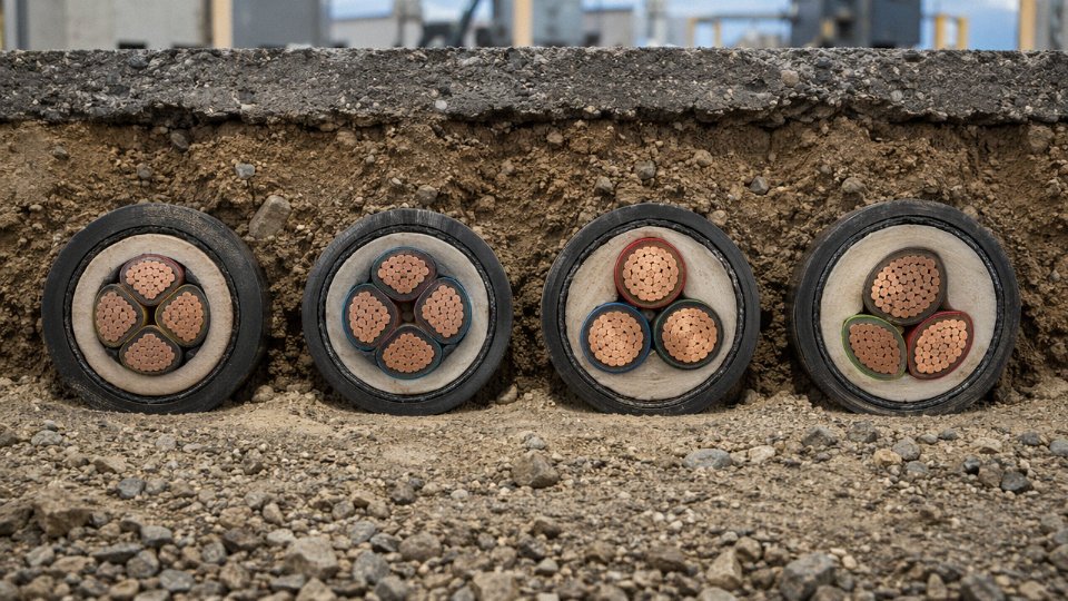
Topside offshore applications are genuinely brutal. Salt spray corrosion, continuous low-frequency vibration from platform movement and machinery, and occasional hydrocarbon splash combine in ways that accelerate every failure mode simultaneously. SWA design life in topside service drops to roughly 20–25 years even with diligent maintenance — and that assumes the cable was properly specified from the start with tinned copper conductors, EPR insulation rated for wet thermal aging, and an LSZH-FR outer sheath.
EPR insulation outperforms XLPE in offshore wet-heat aging environmentsTrue
EPR (ethylene propylene rubber) has superior resistance to moisture absorption and maintains dielectric properties at elevated temperatures in the presence of water, making it the preferred insulation for offshore and subsea armored cable applications where XLPE water treeing is a documented failure risk.
The mechanical loading piece is underappreciated. Cables routed across expansion joints or through cable trays on a floating production unit experience cumulative fatigue at support points. Standard SWA with galvanized steel wires is marginal here; many offshore specs now call for stainless steel wire armor or braided configurations where bending radius is tight.
Underground Coal and Hard-Rock Mining
Mining trailing cables live a completely different life. In continuous miner applications — where the cable flexes thousands of times per shift, runs over sharp floor debris, and operates in methane-classified atmospheres — a service life of 3–7 years is not a sign of poor cable quality. It reflects the duty cycle. These cables are maintenance items, not long-life assets, and any procurement model that treats them otherwise ends up understocking spares and creating unplanned downtime.
The armor construction for trailing mining cables is typically flat steel tape or steel wire braid optimized for repeated tight bending rather than static burial loads. Methane atmosphere requirements push the sheath and insulation toward certified flame-retardant compounds, which sometimes trade a degree of mechanical toughness for compliance — a tradeoff mining engineers know well.
Wind Farm Collector Cables
Offshore and coastal wind farm developers have pushed the specification envelope harder than almost any other sector in the last decade. A 33 kV XLPE SWA collector cable in a coastal direct-burial installation faces moisture-rich soil, variable thermal loading tied to wind intermittency, and the financial reality that replacing buried cables mid-project destroys the economics. Project bankability now routinely requires demonstrating a 40-year design life, which in practice means longitudinal water-blocking tape under the armor, an enhanced oversheath, and third-party type test documentation that satisfies lender technical advisors.
Thermal cycling from variable generation is a real aging driver. A cable that sits at 30% load during low-wind periods and then surges to full rated current during a storm front cycles its insulation and conductor interfaces repeatedly. Over 40 years, that accumulates. Specifying cables with margin on the continuous current rating — rather than running at 95% of rated capacity — extends insulation life measurably.
Railway and Metro Systems
Stray DC traction current corrosion is the failure mode that surprises engineers new to rail infrastructure. Near DC return rails, unprotected SWA armor can experience galvanic dissolution in as little as 5–8 years. The mechanism is straightforward: stray current exits the rail, travels through moist soil, and enters the cable armor as the path of least resistance; where it exits back into the soil, it corrodes the steel electrochemically. The result looks nothing like conventional corrosion — pitting is localized and often severe, while adjacent armor wires look perfectly intact.
The standard response in modern metro systems is double insulation on the armor plus impressed current cathodic protection for cable routes in tunnel sections. Vibration fatigue at cable cleats and supports is a secondary issue, particularly where cables are fixed at intervals that create resonant spans under train-induced vibration. In practice, support spacing for armored cables in rail tunnels is tighter than in static industrial installations, and the cleat design matters — rigid steel cleats that abrade the outer sheath over years are a surprisingly common source of early failures.
How to Specify Armored Cable for Maximum Lifespan: A Procurement Checklist
Getting 35 years out of an armored cable installation instead of 18 rarely comes down to luck. It comes down to what you wrote in the specification before the purchase order was issued. By the time cable is in the ground, most of the decisions that determine its real service life have already been made — or missed.
Define the Operating Environment Before Touching a Data Sheet
The single most damaging procurement habit is selecting a cable type and then asking suppliers to confirm it’s suitable. Reverse that. Require the project team to formally document soil resistivity (measured, not estimated — values can swing from under 10 Ω·m in waterlogged clay to over 1,000 Ω·m in dry sandy terrain), peak ambient temperature at burial depth, any chemical exposure profile including pH, sulfate concentration, and hydrocarbon presence, and the installation method: direct burial, duct, tray, or underwater.
Hand that document to suppliers and ask them to confirm suitability in writing. A reputable manufacturer will push back or ask follow-up questions. One who simply says “yes, no problem” to everything is a flag worth noting.
Third-Party Type Test Certificates — and How to Read Them
Specify which standard applies. IEC 60502-2 for medium-voltage power cables, the IEC 60092 series for marine and offshore applications, IEC 60245 or 60227 for flexible armored cables. These are not interchangeable. Then ask for current certificates — issued within roughly the last five years — from an accredited body. KEMA (now KEMA-DEKRA), CESI, and CPRI are well-recognized; a certificate from an unknown in-house lab attached to the manufacturer’s own quality department does not carry the same weight.
IEC type test certificates issued by the cable manufacturer's own internal laboratory carry equivalent weight to those from independent accredited bodies.False
IEC standards require type tests to be performed by independent, accredited third-party laboratories to ensure impartiality. Manufacturer-issued self-certification does not satisfy this requirement for project-critical procurement.
Check that the certificate covers the actual construction being supplied — conductor size, insulation grade, armor configuration, sheath material. A certificate for a 95 mm² cable tells you very little about the 240 mm² variant being shipped to your site.
Conductor Material and Temper
For most industrial and utility direct-burial work, annealed plain copper per IEC 60228 Class 2 is adequate. In continuously flexing applications — trailing cables in mining, for instance — Class 5 stranded copper is worth the price premium. Tinned conductors make sense anywhere persistent moisture is a factor, particularly in coastal or below-grade marine installations.
Avoid aluminum conductors below 35 mm² for anything that requires field terminations by general electrical contractors. The oxidation layer that forms at aluminum joints under cyclic loading creates resistance hotspots that quietly cook the insulation over years. This is not a theoretical concern; it shows up in insulation resistance trends well before visual inspection catches it.
Armor and Sheath Combinations That Match the Duty
| Installation Context | Armor Type | Outer Sheath | Notes |
|---|---|---|---|
| Direct burial, general | Galvanized SWA | PVC or HDPE | Verify zinc coating mass per IEC 60227 |
| Marine / offshore | AWA (tinned copper wires) | LSZH | Halogen-free matters in enclosed spaces |
| Chemical plant / process area | SWA or STA | LSZH or polyurethane over inner PVC bedding | Double-sheath adds chemical resistance layer |
| Tray, no burial | SWA | PVC | Lighter armor acceptable; UV-stabilized sheath if exposed |
For direct burial, the zinc coating mass specification matters more than most buyers realize. A lighter coating degrades within a decade in acidic soils; a heavier galvanizing spec adds modest cost but can add years of armor integrity in aggressive ground conditions.
Factory Acceptance Test Records as a Baseline Asset
Request full FAT documentation — not a summary, the actual results. At minimum: high-voltage withstand (conductor-to-armor and conductor-to-conductor), partial discharge test results for any MV cable, and per-conductor resistance measurements. These numbers are only useful if you keep them. Filed properly, they become the baseline against which future diagnostic tests are compared. An insulation resistance reading taken at commissioning that’s later measured at 30% of the original value tells you something actionable. A number in isolation tells you almost nothing.
Assessing Manufacturer Supply Chain Depth
Ask whether the manufacturer draws its own conductors and extrudes its own insulation in-house. Vertical integration is not glamour — it’s process control. When a manufacturer buys conductor from three different suppliers depending on market price, you get inter-batch variability in temper and surface condition that affects both termination behavior and long-term insulation adhesion.
References from comparable projects matter more than generic ISO certificates. Ask specifically for installations in similar environments — comparable soil chemistry, temperature range, voltage class — that have been in service for at least five to eight years. A manufacturer who can provide commissioning-to-present operational data from a reference project in a similar context has demonstrably earned that claim.
Frequently Asked Questions About Armored Cable Lifespan
How long does SWA cable last underground?
Properly installed galvanized SWA cable with a PVC outer sheath in normal, non-aggressive soil will typically achieve 30–40 years of service life. That range depends heavily on soil resistivity, moisture consistency, and whether the burial depth meets the 0.5 m minimum for LV or 0.9–1.2 m for HV installations per IEC and NEC guidance.
The figure drops sharply in aggressive soils. Where soil resistivity falls below roughly 1,000 ohm-cm — common near coastal reclamation sites, industrial fill, or areas with high sulfate content — the galvanized armor can show measurable corrosion within 10–15 years even when the cable itself was correctly installed. In those conditions, specifying an HDPE outer sheath instead of PVC, adding a bitumen bedding layer, or routing through conduit isn’t over-engineering; it’s the difference between a 35-year asset and a mid-life emergency replacement. Soil testing before trench design is cheap. Emergency excavation through a live industrial yard is not.
Galvanized SWA cable in non-aggressive soil typically achieves 30–40 years underground service life when installed to IEC depth requirementsTrue
This range aligns with IEC 60502 design life parameters and is consistent with observed field performance in utility and industrial installations under normal soil conditions.
Does armored cable deteriorate in storage?
Yes, and this catches procurement teams off guard more often than it should. PVC insulation relies on plasticizer content for flexibility and dielectric stability, and plasticizer migration continues slowly at ambient temperature even when the cable is sitting on a drum doing nothing. Cables stored beyond roughly two years — especially in warm or UV-exposed conditions — should be treated with the same caution as aged field cable: insulation resistance testing, a visual check of the sheath for surface cracking or brittleness, and end-cap verification before installation.
Drums should be stored upright, in covered warehousing, away from direct sunlight and clear of chemicals or solvents. Flat-stacking drums causes permanent deformation of the inner layers over time. It sounds obvious, but I’ve seen projects delayed because a batch of “new” cable stored outdoors on a coastal site for 18 months failed IR testing during pre-installation checks. The cable was new on paper and unusable in practice.
Can armored cable be repaired once damaged?
Localized mechanical damage — a dig-in, a crush point — can be addressed using IEC-qualified heat-shrink or cold-applied jointing systems, and done correctly these repairs restore electrical integrity. The honest caveat is that repaired sections become the statistically weakest point in the entire run. On a cable already 20 or more years into service, a repair is usually buying time rather than restoring the asset. Plan for replacement; use the repair to keep operations running until that replacement is scheduled.
What is the difference between design life and service life?
Design life is the engineered rating — the period a cable is expected to perform without unacceptable degradation under its specified installation and operating conditions. IEC 60502 anchors this at 25–40 years depending on construction and environment. Service life is what actually happens. Poor installation, chronic overloading, unexpectedly aggressive soil, or a through-fault event can all compress service life well below the design figure. Conversely, a cable running at 60–70% of rated current in stable, dry conditions often outlasts its design life without any drama.
How does cable lifespan affect total cost of ownership?
A 40-year design life cable typically costs 15–25% more at procurement than a 25-year equivalent — the exact premium depends on armor specification, insulation grade, and sheath material. That upfront difference funds the elimination of one complete replacement cycle. The material cost of that second cable purchase is actually the smaller part of the equation. Trench excavation, production shutdown, safety management, and schedule disruption in an operational facility routinely run several times the cable cost itself. On any project where replacement would require breaking into a live process area, the longer-life specification almost always wins on a lifecycle basis.
How do I know when armored cable needs replacement rather than maintenance?
Several specific diagnostic thresholds point toward replacement rather than continued monitoring. On MV cables, tan-delta values exceeding 0.008 at U₀ indicate insulation degradation that maintenance cannot reverse. On LV cables, a polarization index below 1.0 from IR testing signals compromised insulation condition. TDR traces showing multiple distributed reflection anomalies — rather than a single identifiable fault — suggest generalized insulation breakdown along the run. Any cable older than roughly 20 years that has experienced a through-fault event should be evaluated for replacement rather than return to service; the thermal and mechanical stress of a fault on aged insulation tends to accelerate remaining life consumption faster than most diagnostic intervals can track.
These thresholds aren’t conservative estimates. They represent the point where continued operation risk — an unplanned fault, a safety incident, a production outage — starts to outweigh the cost and disruption of planned replacement.