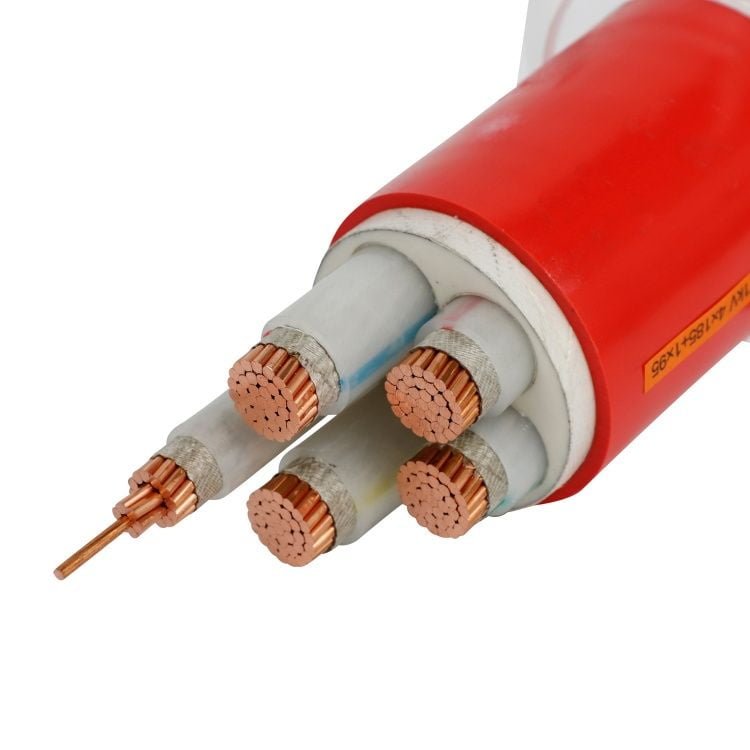
Mislabeling coax as “just another cable” is the kind of mistake that shows up fast — a mismatched impedance on an RF line produces reflections that eat signal before it reaches the load, and a power cable substituted into a video distribution run will introduce enough attenuation and noise to render the system useless. In procurement, the confusion costs more than rework: wrong-spec cable ordered in bulk means storage, returns, and schedule slippage that can run a project weeks behind before anyone admits what happened.
No, cable and coaxial cable are not the same thing. All coaxial cable is cable, but the reverse is not true. Coaxial cable is a specific construction — a center conductor, dielectric, braided or foil shield, and outer jacket — engineered to a defined characteristic impedance (50 Ω or 75 Ω depending on application) and optimized to carry high-frequency signals with controlled attenuation. General-purpose cable carries power or low-frequency signals and is built to entirely different standards.
What makes this worth understanding beyond the dictionary definition is the engineering distance between the two. An RG-6 coax loses roughly 6 dB per 100 ft at 900 MHz; a comparable power cable in the same run would perform far worse at that frequency, not because it is poorly made, but because it was never designed for that job. The global coaxial cable market sits at around USD 11 billion — real, but a specialized slice of a broader wire and cable industry that exceeds USD 200 billion. That size gap tells you something about how narrowly coax is actually applied, and why conflating it with general cable creates problems the moment specifications start to matter.
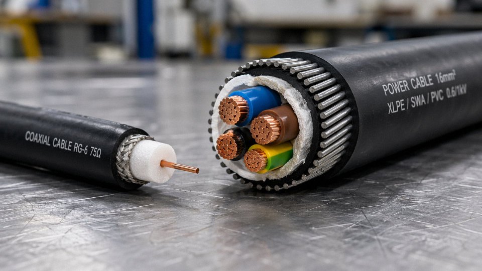
Anatomy of a Generic Cable: Conductors, Insulation, and Jacket Layers Explained
Start pulling apart any standard power or control cable and you’ll find a surprisingly consistent architecture — conductor, insulation, optional bedding or filler, and jacket. That’s it. The variations within each layer are enormous, but the basic stack stays the same whether you’re looking at a 0.5 mm² instrument cable in a control panel or a 630 mm² feeder running to a substation transformer.
Conductors: The Current-Carrying Core
Most cables use copper or aluminum conductors, either solid or stranded. Solid conductors are cheaper and dimensionally stable, which makes them fine for fixed installations where you’re not bending the cable repeatedly. Stranded construction — multiple smaller wires twisted together — gives you flexibility, better resistance to fatigue cracking, and easier termination in tight spaces. For anything that moves or flexes in service (a drag chain, a reeling drum, equipment with vibration), stranded is the only sensible choice, and finer stranding (Class 5 or Class 6 per IEC 60228) costs more but survives the mechanical abuse.
Cross-sectional sizes span a huge range. Control and instrumentation cables typically run 0.5 mm² to 2.5 mm², where the priority is signal integrity and panel density, not current-carrying capacity. General power cables for motors, panels, and feeders commonly run 4 mm² up through 240 mm² or so. Get into high-voltage transmission or large industrial feeders — offshore platforms, aluminum smelters, large data center MV feeds — and you’re looking at 400 mm² to 630 mm², sometimes larger for special applications. At that size, aluminum often wins on cost-per-ampere even though it’s a worse conductor by volume, because the weight and material cost savings are difficult to ignore.
Insulation: Where Material Selection Actually Matters
The insulation layer sits directly over the conductor and does most of the electrical work. XLPE (cross-linked polyethylene) dominates medium- and high-voltage applications because of its high dielectric strength, good thermal rating (typically 90°C continuous, 250°C short-circuit), and solid track record in IEC 60502-compliant cables. PVC is cheaper and widely used at low voltage — it’s the default for most building wiring and control cables — but its temperature ceiling is lower, usually 70°C continuous, and it softens in heat and becomes brittle in cold. EPR (ethylene propylene rubber) is the go-to when you need flexibility at low temperatures or resistance to water ingress, which is why you see it on offshore and marine cables even though it costs roughly 20–40% more than XLPE depending on compound grade and order volume.
XLPE-insulated cables rated to IEC 60502 can operate continuously at 90°C conductor temperatureTrue
IEC 60502 and the relevant IEC 60228 conductor standards specify 90°C as the maximum continuous operating temperature for XLPE insulation in medium-voltage cables, a figure that determines ampacity calculations and derating factors.
Voltage class drives insulation thickness more than almost anything else. Low-voltage cables (up to 1 kV) might carry 0.6–0.9 mm of insulation on a 4 mm² conductor. Step up to medium voltage — say, 11 kV or 33 kV — and IEC 60502-2 specifies insulation walls of 3.4 mm to 8 mm or more depending on the voltage and whether the cable is screened. High-voltage cables above 35 kV bring in additional requirements: metallic screens, semi-conductive layers to smooth the electric field gradient, and insulation thicknesses that can exceed 15 mm. Getting these wrong isn’t an academic concern; inadequate insulation thickness for the operating voltage leads to partial discharge, then insulation breakdown, then a fault that can take a feeder offline for days.
Fillers, Binders, and Jacket
In multi-core cables, the space between round insulated cores gets filled — usually with polypropylene rope, paper, or similar material — to produce a reasonably circular overall profile. Without fillers, the cable is oval or irregular, which makes armoring difficult and creates stress concentration points at the valleys between cores. A binder tape (often polyester) holds the assembly together before the outer layers go on.
The outer jacket is mostly mechanical and environmental protection. PVC, LLDPE, HDPE, or polyurethane are common choices, each with trade-offs in UV resistance, chemical resistance, abrasion resistance, and cost. An armored variant adds a layer of steel wire armor (SWA) or steel tape armor between an inner sheath and the outer jacket, which matters for direct burial, areas with rodent pressure, or any application where the cable might see significant mechanical impact.
The critical point for this article’s argument: none of this construction requires a continuous outer conductor wrapped concentrically around the inner conductor at a controlled geometry. There’s no impedance specification on a 16 mm² XLPE/SWA/PVC power cable. Nobody cares about the capacitance between core and armor in the way that defines a coaxial cable’s entire electrical behavior. That structural absence — no controlled concentric outer conductor, no defined characteristic impedance — is exactly what separates a generic cable from coax, and why you cannot substitute one for the other in RF or precision signal applications regardless of what the voltage ratings look like on paper.
Coaxial Cable Construction: The Concentric Geometry That Defines RF Performance
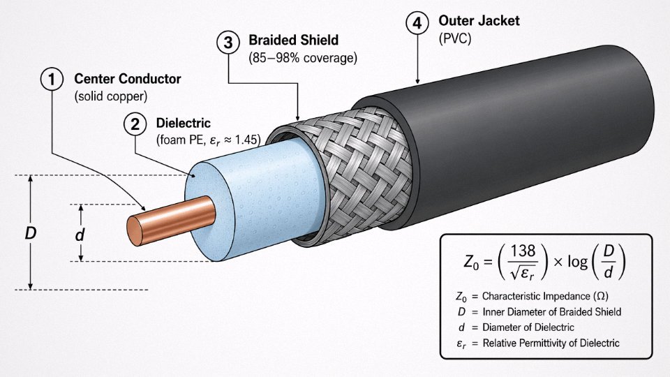
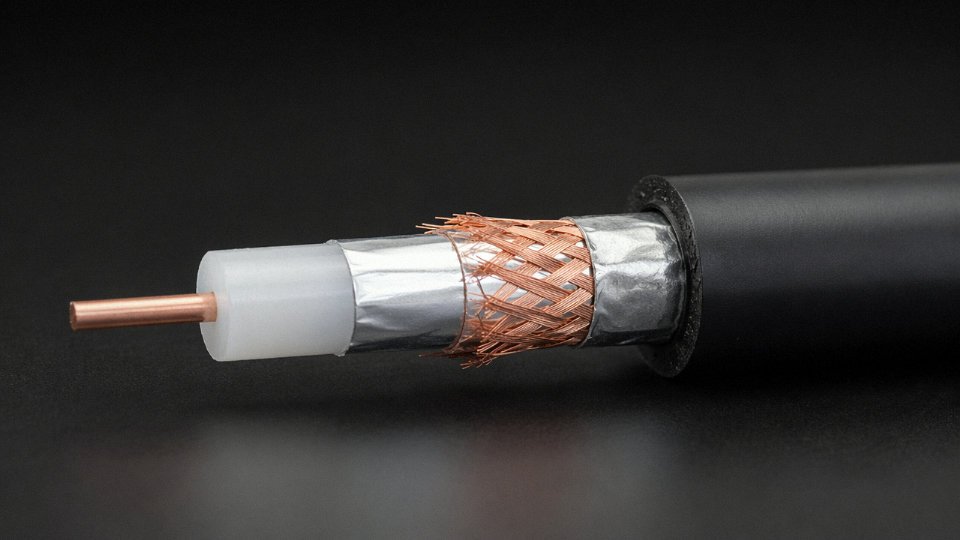
Strip back a coaxial cable and you find four concentric layers, each doing a specific job that the next layer depends on. Get any one of them wrong in manufacturing — diameter tolerance slips, foam density varies, braid coverage drops — and the whole system degrades in ways that are genuinely hard to diagnose in the field.
Center Conductor: The Signal Carrier
The innermost element is solid or stranded copper, though copper-clad steel (CCS) shows up frequently in satellite drop cables where tensile strength matters more than ultimate conductivity. Solid copper gives lower DC resistance and is the preferred choice for higher-frequency work; stranded constructions are more flexible and tolerate installation bending better, but the individual strand gaps create slightly higher RF resistance at frequencies above a few hundred MHz due to skin effect. For something like RG-213 on a transmitter feedline, solid bare copper is standard. For a long aerial run of RG-6 on a residential CATV install, CCS is common and perfectly adequate.
Dielectric: Where Impedance Is Born
Surrounding the center conductor is the dielectric insulator, and this layer does far more work than its equivalent in a power cable. Solid PTFE gives excellent high-temperature performance and very low dielectric loss — it’s the go-to for aviation and military coax, but it’s expensive. Foam polyethylene (foam PE) is the workhorse of the industry: the gas-filled cellular structure reduces the effective dielectric constant (εr typically 1.4–1.5 versus roughly 2.25 for solid PE), which directly lowers attenuation. Air-spaced or helical designs push εr even closer to 1.0 and are used in low-loss hardline runs, though they sacrifice flexibility entirely.
This is also where impedance is set. The characteristic impedance Z₀ follows:
Z₀ = (138 / √εr) × log(D/d)
where D is the inner diameter of the outer conductor and d is the diameter of the center conductor. The practical consequence: if your dielectric concentricity drifts during extrusion — say the center conductor migrates off-axis — D/d becomes inconsistent along the cable length, and Z₀ fluctuates. On a 50 Ω system, that produces impedance mismatches, reflections, and measurable return loss degradation. Holding dielectric concentricity within ±2–3% of nominal isn’t a conservative spec; it’s the minimum to maintain usable impedance consistency. Standard power cable extrusion lines simply aren’t built to that kind of dimensional discipline.
Outer Conductor: The Shield That Completes the Circuit
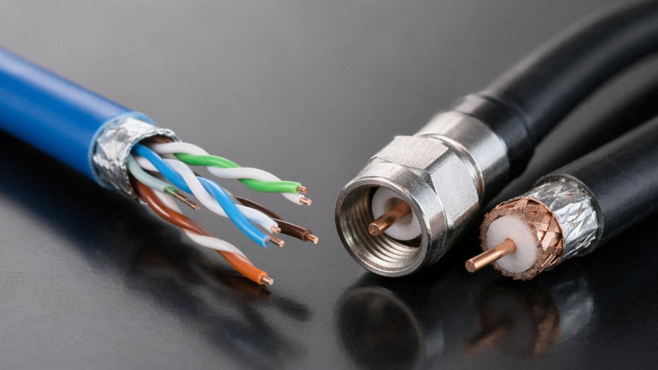
The outer conductor — braid, foil, or solid tube — serves dual duty. It’s the return path for the signal current, and it confines the electromagnetic field entirely to the space between the two conductors. This is the property that makes coax fundamentally different from any ordinary shielded cable. The field doesn’t leak outward, and external fields don’t penetrate inward. A twisted pair with an overall foil screen is not the same thing; the geometry isn’t coaxial, the shield isn’t a true return conductor in the RF sense, and field confinement is incomplete.
Braid shields (RG-58, RG-6) offer good flexibility and 85–98% coverage depending on braid angle and number of carriers. Foil-plus-braid is common in CATV applications for better high-frequency shielding. Solid aluminum tube — hardline — is used in broadcast tower feedlines and CATV trunk lines where attenuation must be minimized over long runs. There’s no flexibility to speak of, but in a fixed installation that’s not a problem.
Jacket and Cable Family Comparison
The outer jacket is PVC for most general-purpose coax, PE or LLDPE for direct-burial and outdoor UV-exposed runs. It’s mostly mechanical and environmental protection; it doesn’t affect electrical performance directly, though jacket dielectric properties matter slightly in very high-frequency microwave coax.
Across the common types, the differences in application become clearer:
| Cable Type | Impedance | Dielectric | Typical Use | Notes |
|---|---|---|---|---|
| RG-6 | 75 Ω | Foam PE | CATV, satellite | Most residential installs; CCS center common |
| RG-58 | 50 Ω | Solid PE | Thin Ethernet, lab RF | Lossy above ~500 MHz; short runs only |
| RG-213 | 50 Ω | Solid PE | High-power RF, amateur radio | Larger diameter, handles higher power than RG-58 |
| LMR-400 | 50 Ω | Foam PE | Low-loss feedlines, wireless infrastructure | Significantly lower attenuation than RG-8/RG-213 |
| Hardline (HELIAX-type) | 50 or 75 Ω | Foam or air | Broadcast towers, CATV trunk | Solid outer conductor; rigid or corrugated |
RG-6 loses approximately 6 dB per 100 ft at 900 MHzTrue
This attenuation figure is consistent with published specifications from major coaxial cable manufacturers for standard RG-6 foam dielectric construction at 900 MHz, and aligns with field measurement experience on CATV and satellite installations.
The attenuation gap between coax types is not trivial. RG-58 at 900 MHz runs roughly 17–19 dB per 100 ft — three times worse than RG-6 — which is why choosing the wrong cable type on even a moderate-length run can kill signal margin completely. The concentric geometry enables the performance; the manufacturing precision maintains it.
Electrical Behavior Compared: Impedance, Attenuation, Shielding, and Frequency Range
Power cables and coaxial cables are optimized for entirely different electrical regimes, and that distinction shows up immediately when you look at the parameters engineers actually specify and test.
DC Resistance vs. Characteristic Impedance
For power cables, the primary electrical design target is DC resistance — specifically, minimizing I²R losses over the conductor’s cross-section. IEC 60228 Class 1 through Class 5 conductors are graded by how tightly resistivity is controlled: a 16 mm² Class 2 stranded copper conductor must stay below roughly 1.15 Ω/km at 20 °C. That’s the number that drives conductor sizing, heat rise calculations, and voltage drop budgets. Nobody specifying a 400 V distribution cable cares about characteristic impedance, because at 50 or 60 Hz the cable length is electromagnetically short — the wave doesn’t “see” the line as a transmission structure.
Coaxial cable is the opposite. Its characteristic impedance — 50 Ω for RF and instrumentation work, 75 Ω for video and CATV — is a geometric property set by the ratio of the outer conductor’s inner diameter to the inner conductor’s outer diameter, and the permittivity of the dielectric between them. Get the geometry wrong by even a few percent during extrusion and the impedance drifts, causing reflections. A power cable manufacturer doesn’t hold those tolerances because they never need to.
Attenuation Across Frequency
This is where the gap becomes quantitative and uncomfortable for anyone who’s tried to substitute a “shielded cable” for a coax run.
At 1 GHz, a standard RG-6 coax runs roughly 12–15 dB of insertion loss per 100 m — the exact figure depends on the dielectric foam density and the braid coverage percentage, both of which vary between commodity and broadcast-grade product. Step up to LMR-400 or equivalent low-loss construction and that drops to around 4–5 dB/100 m at the same frequency, because the larger center conductor (about 8 mm outer diameter overall) and nitrogen-injected PE foam keep both conductor loss and dielectric loss low. For comparison, RG-6 from one reel to another can vary by 10–15% in attenuation if the foaming process isn’t tightly controlled — something worth confirming on the test certificate before a large installation.
General power cables are simply not rated at gigahertz frequencies. There’s no IEC or UL attenuation figure for them above a few kilohertz, because signal integrity is irrelevant to their function. If someone quotes you a power cable for an RF application, the data sheet will be silent on the only number that matters.
A standard RG-6 coaxial cable exhibits roughly 12–15 dB insertion loss per 100 m at 1 GHz, while low-loss LMR-400 type cable drops to approximately 4–5 dB/100 m at the same frequency.True
These figures are consistent with published manufacturer data for RG-6 (solid and foam dielectric variants) and LMR-400 equivalent constructions tested per IEC 61196 or equivalent; exact values depend on dielectric density, braid coverage, and temperature.
Shielding: Safety Screen vs. Transmission-Line Shield
Both cable types can have a metallic shield layer, but the purpose is different enough that comparing them directly misleads procurement decisions.
A screened power cable — the kind used with variable-frequency drives to contain switching noise and meet IEC 61800-3 EMC requirements — uses a copper or aluminum foil, sometimes a braid over that, mainly to provide a low-impedance return path for high-frequency common-mode currents and to protect adjacent instrumentation from radiated interference. Shielding effectiveness in this context is typically characterized at frequencies from a few kHz to maybe 1–2 MHz. It works. But it’s an EMC safety measure, not a controlled transmission environment.
Coaxial shielding does something structurally different: it completes the transmission line. The outer conductor is the return path for the signal current, and its coverage percentage directly controls both attenuation and shielding effectiveness simultaneously. A single aluminum braid at around 85–90% coverage gives roughly 35–45 dB of shielding. Add a foil underneath — the foil+braid construction common in CATV quad-shield — and you’re in the 85–95 dB range. Tri-shield and quad-shield designs, used in environments with strong local RF sources, push past 100 dB. In a plant with high-power radio transmitters nearby, that 60 dB difference between a basic shielded instrumentation cable and a proper quad-shield coax is not academic.
VSWR and Return Loss — Concepts That Don’t Cross Over
Variable Standing Wave Ratio and return loss are coax-exclusive metrics. VSWR quantifies how much of the transmitted signal reflects back toward the source due to impedance mismatches along the line or at terminations. A VSWR of 1.5:1 represents roughly 4% reflected power — acceptable for most industrial RF links. Above 2:1 you’re losing meaningful signal and potentially stressing the source. Return loss below about 20 dB typically triggers investigation in a well-maintained system.
These concepts have no equivalent in power cable selection. You would never specify return loss for a motor feed cable, and trying to measure VSWR on a 6 mm² XLPE conductor would produce a meaningless result. The physics don’t apply.
Frequency Windows in Practice
| Application | Typical Cable Type | Operating Frequency Range |
|---|---|---|
| Mains power distribution | XLPE or PVC power cable | 50/60 Hz |
| VFD motor feeds | Screened power cable | DC to ~5 kHz switching harmonics |
| Process instrumentation | Twisted pair, screened | DC to ~100 kHz |
| CCTV, CATV, satellite | RG-6, RG-11 | 5 MHz – 2.5 GHz |
| Industrial RF, antenna feeds | LMR-400 or equivalent | 50 MHz – 6 GHz |
| Microwave links | Semi-rigid or phase-stable coax | Up to 40+ GHz |
In practice, the frequency boundary around 1–5 MHz is where power/instrumentation cable constructions become genuinely unreliable for signal transmission — impedance is uncontrolled, attenuation rises steeply, and shielding effectiveness degrades in ways that aren’t predictable from the data sheet. That’s roughly where coaxial construction starts to be the only sensible answer.
Standards and Certifications: IEC, MIL-SPEC, and Industry Codes That Separate the Two Worlds
The standards world for cables is not one ecosystem — it’s two largely parallel ones that occasionally share a fence. A procurement manager who pulls up “IEC cable standards” and starts applying whatever comes up first is going to have a bad time, especially at customs or during a third-party factory audit. Power cables and coaxial cables are governed by entirely different document families, written by different working groups, and tested against different parameters. Understanding which standard governs which product is not a technicality — it’s a prerequisite for writing a compliant purchase order.
Power and Control Cable Standards
For general power and control cables, the IEC framework centers on a handful of well-established documents. IEC 60502 covers power cables with extruded insulation from 1 kV up to 30 kV — this is the go-to reference for medium-voltage plant cabling, feeder runs, and most industrial distribution work. Below 1 kV, IEC 60227 governs PVC-insulated cables for fixed wiring and flexible applications, and IEC 60228 defines conductor classes (the Class 1 through Class 6 flexibility spectrum that determines whether a conductor is solid, stranded, or finely stranded). These three documents together cover probably 80% of what a typical industrial plant is actually pulling through conduit.
In North America the landscape shifts. UL 44 covers thermoset-insulated wire and cable; UL 83 handles thermoplastic-insulated wire. ICEA standards — particularly ICEA S-95-658 and related publications — provide additional construction and performance requirements for utility and industrial power cables. If you’re sourcing for a project in the US or Canada, referencing only IEC without confirming UL or ICEA equivalency will create approval problems during installation inspection. That gap catches importers off guard more often than it should.
Coaxial Cable Standards
Coaxial cables live in a different document family entirely. The IEC 61196 series is the main international reference — IEC 61196-1 sets general requirements and test methods, IEC 61196-3 addresses semi-rigid coax (the type used in microwave assemblies and instrument housings), and IEC 61196-6 covers flexible RF coaxial cables used in broadcast, instrumentation, and similar applications. These documents specify things like characteristic impedance tolerance, velocity of propagation, return loss, and screening attenuation — parameters that simply don’t appear in power cable standards because they’re irrelevant to 50 Hz or 60 Hz current delivery.
For military and aerospace procurement, MIL-DTL-17 (formerly MIL-C-17) is the controlling document for the RG-series cable types. It defines construction, impedance, maximum attenuation, and environmental performance for dozens of cable types across the 50 Ω and 75 Ω impedance families. If a supplier quotes “MIL-SPEC coax” without referencing a specific slash sheet from MIL-DTL-17, that claim is essentially meaningless — push back and ask for the exact type designation.
European CATV and distribution coax falls under EN 50117, which is a multi-part series covering cables from subscriber drops through trunk distribution. EN 50117 specifies screening effectiveness classes (Class A through Class A+++, roughly), which matter enormously for interference performance in dense urban deployments.
Fire Performance and Cross-Cutting Regulations
Here’s where the two families do share common ground. IEC 60332 (flame propagation tests), IEC 60754 (halogen acid gas emission), and the LSZH requirements embedded in IEC 60332-3 and EN 50267 apply across both cable types — but they are tested and specified independently for each product line. A coaxial cable installed in a plenum or a public building still needs to meet the relevant fire class; buying an LSZH-rated power cable does not tell you anything about the fire performance of the coaxial cable running alongside it.
CE marking, RoHS compliance, and REACH substance restrictions are similarly cross-cutting. Any cable sold into European markets — whether it’s a 35 mm² power cable or an RG-6 quad-shield coax — is subject to these requirements regardless of its electrical function.
RoHS and REACH compliance requirements apply equally to coaxial cables and power cables sold in the EU, regardless of the cable's electrical purpose.True
RoHS Directive 2011/65/EU and REACH Regulation (EC) No 1907/2006 apply to electrical and electronic equipment and chemical substances across product categories without exempting specific cable types based on function. Both coaxial and power cables must comply when placed on the EU market.
The Audit and Customs Risk
In practice, the most common non-conformance scenario goes like this: a buyer specifies a fire-performance requirement by citing IEC 60332-1-2 on the purchase order, but the shipment contains coaxial cable tested only to IEC 60332-1-1 (a lower-severity test). The cables look similar on a visual inspection. The difference only surfaces during a third-party audit or, worse, a customs examination in a market with active enforcement. The cost is re-testing, potential detention, and in some cases re-procurement on a tight project schedule.
The fix is straightforward — require test reports keyed to the exact IEC or UL document and part number relevant to that cable type, not a generic declaration of compliance. For coax specifically, ask for IEC 61196-series test data alongside any fire or environmental certificates. They are separate documents for a reason.
Application Mapping: Where Each Cable Type Is Mandated by Design, Not Preference
The word “mandated” matters here. In most of the applications below, using the wrong cable family doesn’t just create a performance penalty — it creates a standards non-compliance, a warranty void, or in the worst cases, a safety incident. Preference doesn’t enter into it.
Where Coaxial Cable Is Required, Not Optional
Antenna feedlines are the clearest case. At a cellular base station, the run from the radio unit to the panel antenna operates at 700 MHz to 3.5 GHz depending on the band. Ordinary shielded cable has no defined characteristic impedance, so any impedance mismatch at that frequency range causes reflected power, standing waves, and measurable output loss. The antenna system simply won’t perform to spec. The same logic holds for broadcast transmitter feedlines, satellite uplink dishes, and even a modest amateur radio installation — the physics requires 50 Ω coax, full stop.
CATV and MATV distribution networks are wired to 75 Ω throughout by system design. Every passive splitter, amplifier, and tap in the trunk is matched to that impedance. Substitute anything else and the return loss figures collapse. RF laboratory instrumentation — network analyzers, signal generators, spectrum analyzers — ships with SMA or N-type 50 Ω ports because the measurement uncertainty budgets assume that impedance. Plug in a random shielded cable and you’re no longer measuring your device; you’re measuring the cable mismatch.
Radar systems and internal RF routing inside telecom equipment follow the same logic, just at higher stakes. A waveguide-to-coax transition on a marine radar head is not a place for improvisation.
Where General Cable Is Required
Building power distribution under IEC 60364 demands cables rated for voltage class, current-carrying capacity, and installation method — none of which coaxial cable addresses. Motor feeders in industrial plants need cables specified for continuous current, short-circuit withstand, and often mechanical protection; coax offers none of that.
Solar PV string wiring is a good example of how specific the mandates get. IEC 62930 (or USE-2/PV Wire in North American projects) requires UV resistance, specific temperature ratings, and double insulation — a very particular cable family that isn’t coax and isn’t generic building wire either. Offshore and marine power runs under NEK 606 or IEC 60092 require mud-resistant, flame-retardant, halogen-free constructions with defined short-circuit performance. Railway traction supply under EN 50264 has its own fire and smoke requirements that narrow the field considerably.
The Grey Zone Where Mistakes Happen
Security camera cabling causes genuine confusion on job sites. Analog CCTV systems were historically wired with RG-59 or RG-6 coax — 75 Ω, correct impedance for composite video. IP cameras running over Ethernet need Cat5e or Cat6 UTP, not coax. Mixing them up is more common than it should be, especially on retrofit projects where the conduit was originally installed for analog systems.
Industrial sensor loops are another messy area. A 4–20 mA loop uses shielded instrument cable — twisted pair with an overall foil shield is usually sufficient. But high-frequency sensors, certain vibration probes, and anything feeding directly into a spectrum analyzer port may require triaxial cable with a defined impedance. The two look superficially similar in a parts catalog and are very different in a high-impedance measurement circuit.
5G distributed antenna system (DAS) deployments complicate things further. The RF signal travels over coax from the base unit to remote radio heads, but at some point in the building it may transition to fiber and back. The coax segments still need to be 50 Ω, correctly rated for frequency, with low-PIM connectors if passive intermodulation matters — and it usually does in a dense urban DAS.
Application Decision Table
| Application | Frequency Range | Required Cable Family | Key Standard | Common Mistake |
|---|---|---|---|---|
| Cellular base station feedline | 700 MHz – 3.5 GHz | 50 Ω coaxial | IEC 61196 / MIL-C-17 | Using STP data cable |
| CATV trunk distribution | 5 MHz – 1 GHz | 75 Ω coaxial | IEC 61196-1 | Mixing 50 Ω and 75 Ω hardware |
| RF lab instrumentation | DC – 18 GHz+ | 50 Ω coaxial | MIL-DTL-17 | Generic shielded cable |
| Building power distribution | 50/60 Hz | Low-voltage power cable | IEC 60364 | Coax used “because it has a shield” |
| Solar PV string wiring | DC | PV Wire / IEC 62930 cable | IEC 62930 / USE-2 | Standard building wire outdoors |
| Offshore power | 50/60 Hz | Marine power cable | IEC 60092 / NEK 606 | General industrial cable |
| Analog CCTV camera | 0 – 6 MHz composite | 75 Ω coaxial (RG-59/RG-6) | — | Cat5e UTP |
| IP camera (PoE) | Ethernet (100 MHz) | Cat5e/Cat6 UTP | TIA-568 | Coax left over from analog era |
| Industrial 4–20 mA loop | DC / audio frequencies | Shielded instrument cable | IEC 60079-14 (hazardous areas) | Triaxial cable (overkill) |
| Railway traction supply | 50/60 Hz | Traction cable | EN 50264 | General-purpose power cable |
One Project, Both Families
A port facility is a useful illustration of why a manufacturer’s breadth actually matters in procurement. The same project requires heavy-duty power cables for quayside crane feeders and shore-power connections, marine-rated cables running through cable trays in wet zones, and 50 Ω coaxial cables for the VHF/UHF navigation and communications systems in the harbor master building. These aren’t interchangeable, and they don’t come from the same product line. A supplier that can provide both families — from audited production, with test reports for each relevant standard — removes a coordination problem that otherwise lands on the procurement manager’s desk. In practice, splitting the order across two or three vendors to get compliant product on both sides of that spec boundary is exactly the kind of friction a capable integrated manufacturer should be able to eliminate.
Coaxial cables are manufactured to precise characteristic impedances (50 Ω or 75 Ω), while general-purpose power cables have no characteristic impedance specification, making them electrically incompatible substitutes in RF applications.True
Characteristic impedance in coaxial cable is a function of the conductor diameter ratio and dielectric constant, held to tight tolerances during manufacture. Power cables are designed for current-carrying capacity and insulation voltage rating, with no geometry control for impedance — a fundamentally different design objective confirmed by IEC 61196 versus IEC 60364 scope definitions.
How Coaxial Cables Are Made: Manufacturing Tolerances That General Cable Lines Cannot Match
The practical gap between coaxial and general-purpose cable starts long before installation. It starts on the production floor, in the tolerances held during drawing, extrusion, and braiding — and in the capital equipment required to hold them.
Center Conductor Drawing: Where Dimensional Control Begins
For small-diameter coax — RG-58, RG-174, and their equivalents — the center conductor is drawn to diameter tolerances in the range of ±0.01 mm, sometimes tighter for precision RF types. That sounds modest until you consider what it means for impedance. Characteristic impedance in a coaxial line is set by the ratio of the outer conductor diameter to the inner conductor diameter and the dielectric constant of the material between them. A center conductor that wanders by even 0.03 mm across a production run will shift the impedance by a measurable amount — not catastrophic in a short patch cord, but potentially a signal integrity problem across hundreds of meters of installed cable, especially above a few hundred MHz.
The copper itself matters here in a way it simply doesn’t for power cable. ETP copper at 99.9% minimum purity is standard for coax center conductors — not primarily for conductivity, though that matters, but because impurities and grain structure inconsistencies affect the drawing behavior and surface finish. At RF frequencies, current travels predominantly in a thin skin layer at the conductor surface. Surface roughness is not cosmetic; it adds attenuation. Power cable copper has to carry current efficiently and survive thermal cycling and pulling forces. The surface finish requirements are in a completely different register.
Dielectric Extrusion and Real-Time Concentricity Monitoring
The dielectric layer in coaxial cable — whether solid PTFE, solid PE, or foamed PE — has to be extruded concentrically around the center conductor with tight control on wall thickness uniformity. The production lines used for this run capacitance monitors inline, continuously. If the dielectric goes eccentric, the line capacitance per unit length drifts, and the impedance follows. Catching that in real time lets the operator correct it before meters of off-spec cable accumulate on the take-up reel.
Foamed PE dielectrics add another variable: foam density consistency. Lower density reduces the effective dielectric constant and lowers attenuation, which is why foam dielectric coax outperforms solid dielectric at high frequencies. But if the foam cell structure is inconsistent — denser in some sections, lighter in others — the velocity of propagation varies along the cable, and the characteristic impedance is not stable. General-purpose insulation extrusion lines aren’t designed to manage this. They optimize for mechanical integrity and thermal endurance, not dimensional geometry.
Outer Conductor Application: Braiding, Foil, and Hardline Forming
The outer conductor goes on in one of several ways, and the choice has real consequences. Wire braid coverage percentage — typically 85–98% depending on the construction — directly determines shielding effectiveness and also affects flexibility and bend radius. The braid angle matters too; a shallow angle gives better shielding at lower frequencies, while a steeper angle holds up better to repeated flexing. Dual-braid and braid-over-foil constructions add layers of complexity but also shielding performance that some instrumentation and broadcast applications genuinely require.
Foil wrapping uses a bonded aluminum-polyester tape applied longitudinally with a controlled overlap, typically 20–25%. Getting that overlap consistent requires proper tension control on the foil pay-off and a stable line speed. Variations in overlap reduce shielding continuity.
Hardline coax — the corrugated or smooth-wall aluminum tube type used in trunk cable and high-power RF feeds — is formed differently again. The outer conductor is a continuous tube, either corrugated for flexibility or smooth for the lowest possible attenuation. Forming this accurately requires dedicated tube-forming machinery that has no equivalent on a standard power cable line.
Production Testing Protocols That Power Cable Lines Don’t Run
A finished coaxial cable production reel doesn’t leave a serious plant without swept-frequency impedance testing across its rated bandwidth, not just a spot check at one frequency. Velocity of propagation measurement confirms that the dielectric is behaving as specified. Structural return loss testing — SRL, per IEC 61196 and relevant CATV standards — identifies periodic impedance variations along the cable length that might be invisible to a single-point test but that cause signal ghosting in video distribution systems.
Shielding effectiveness testing per IEC 62153-4 requires a test cell setup that general cable manufacturers simply don’t have configured in their QC labs. The investment in this equipment is one reason coaxial cable production doesn’t easily migrate to a power cable facility.
Coaxial cable production requires fundamentally different capital equipment, inline monitoring systems, and QC protocols compared to standard power cable manufacturing, which is why the two product types are not interchangeable from a sourcing perspective.True
The dimensional tolerances, concentricity requirements, swept-frequency electrical testing, and shielding effectiveness measurement protocols used in coax production are not part of standard power cable manufacturing practice. Equipment, metrology, and process control differ significantly across the two production environments.
The cost and lead time differences procurement teams sometimes find surprising are a direct consequence of this. A power cable facility running at high throughput is optimizing for completely different metrics than a coax line holding ±0.01 mm on conductor diameter while monitoring inline capacitance. Treating them as interchangeable on a bill of materials is where sourcing problems usually start.
Selecting the Right Cable for Your Project: A Practical Specification Checklist
Getting to the right cable spec before you issue a purchase order is always faster than fixing a misspecification on site. The six steps below are not theoretical — they reflect the sequence a competent engineer should work through, in order, before touching a supplier catalog.
Step 1 — Define What the Cable Is Actually Carrying
Start with the most basic question: is this cable moving power or information? AC or DC power requires a cable rated for working voltage and continuous current, full stop. Low-level analog signals — thermocouples, 4–20 mA loops, strain gauges — need shielded instrumentation cable but generally not coax. Digital data below about 1 MHz can usually run on twisted pair.
RF signals above 1 MHz almost always require coaxial cable. Above roughly 10 MHz, the physics stop being optional. A general-purpose shielded cable will radiate, pick up interference, and suffer attenuation that no amount of careful routing will fix. In practice, if a system engineer hands you a spec that says “shielded cable” for a 433 MHz sensor link, push back and ask for the actual impedance requirement. That conversation saves a failed installation.
Step 2 — Lock Down Frequency, Bandwidth, and Impedance Before Opening Any Datasheet
If the application is RF, document three numbers before you look at a single product page: maximum operating frequency, the insertion loss budget for the entire run, and the required characteristic impedance — 50 Ω for RF/instrumentation, 75 Ω for video and CATV distribution. These are not interchangeable. Terminating a 75 Ω system with 50 Ω cable introduces a reflection that shows up as signal degradation or, in broadcast work, visible picture artifacts.
RG-6 at 900 MHz loses roughly 6 dB per 100 ft. If your link budget only allows 10 dB of cable loss and your run is 200 ft, you need lower-loss coax — a larger diameter, foam-dielectric type — or a repeater. Do the math before the cable ships.
Step 3 — Map the Installation Environment to Construction Requirements
Environment drives construction more than any other variable. Direct burial requires armoring or a medium-density PE outer jacket, per IEC 60502-1 guidance. Offshore or marine installations demand halogen-free, mud-resistant compounds — and “low-smoke” on the datasheet is not the same as halogen-free; verify the test standard cited. High-flex applications need Class 5 or Class 6 finely stranded conductors for power cables, or spiral-wound outer conductors for coax; ordinary coax braid fatigues and opens in continuous-flex cable tracks, usually within a few months. High-temperature environments push you toward PTFE-dielectric coax or XLPE-insulated power cable depending on the application.
Seasonal effects matter too. In climates with hard winters, PVC jackets stiffen dramatically below about −15 °C and can crack during installation. Specify low-temperature-rated compounds if the cable will be pulled in cold conditions.
Step 4 — Identify the Governing Standard and Demand Third-Party Evidence
List the applicable standard for the end use — IEC, UL, MIL-SPEC, or a regional utility code — and require that the supplier provide third-party test reports, not self-declarations. A supplier declaration that a cable “meets IEC 60228 Class 5” costs nothing to print. An accredited lab report costs real money and means someone actually measured it.
A supplier's self-declaration of compliance is sufficient evidence of cable specification conformance for industrial procurement.False
Self-declarations are unverified and carry no independent accountability. Industrial and infrastructure procurement should require third-party test certificates from accredited laboratories, particularly for parameters like conductor resistance, insulation breakdown voltage, and flame performance, which directly affect safety and system reliability.
Step 5 — Run the Numbers Before You Finalize Cable Cross-Section or Type
For single-phase power runs, voltage drop (V) = (2 × L × I × R) ÷ 1000, where L is run length in meters, I is current in amps, and R is conductor resistance in Ω/km. Most utilities and building codes cap acceptable voltage drop at 3–5% of nominal — check the applicable regulation for your region.
For RF runs, link loss budget (dB) = sum of connector losses + (cable loss per meter × total length). Connector losses on coax are easy to underestimate; a mediocre field-fitted BNC or F-connector adds 0.3–0.8 dB per joint, and a long run with a dozen connectors can blow your budget before the cable itself becomes the problem.
Step 6 — Validate Supplier Capability Before Committing Volume
Request factory audit reports, production capacity figures (realistic ranges, not marketing claims), and sample test certificates before placing a bulk order — especially on projects that require simultaneous delivery of both power cable and coaxial cable families, which typically come off entirely different production lines with different lead times. A supplier quoting short delivery on both simultaneously is worth scrutinizing. Ask specifically about their RF cable manufacturing tolerances: dielectric diameter control and shield coverage percentage are the two parameters that general cable lines routinely cannot hold to coax-grade consistency.
Frequently Asked Questions About Cable and Coaxial Cable
Can I use regular cable instead of coaxial cable for an antenna connection?
No — and this mistake is more common than it should be, especially on job sites where someone grabs whatever copper is on the reel. A standard power cable or unshielded signal wire cannot sustain the 50 Ω or 75 Ω characteristic impedance that an RF transmission line requires. The result is impedance mismatch at every junction, which causes reflections, standing waves, and signal loss that compounds over frequency. At 900 MHz, you’re also looking at the cable acting as an unintended antenna itself — radiating energy it should be confining, and picking up ambient noise it should be rejecting. In practice, antenna installations using substitute cable will almost certainly fail site acceptance testing and, depending on jurisdiction, may trigger regulatory emissions violations. Not a paperwork problem — an actual re-work problem, with the cable already pulled through conduit.
A standard power cable can substitute for coaxial cable in an antenna feed run if the distances are short.False
Even over short runs, the absence of controlled characteristic impedance causes RF reflections and signal degradation; the cable also lacks adequate shielding to prevent radiation or interference pickup, regardless of run length.
Is coaxial cable safe to carry mains voltage?
It is not rated for it, and using it that way is a code violation in every jurisdiction I’m aware of. Coaxial cable dielectrics — typically foam or solid polyethylene — are engineered for controlled RF propagation, not for sustained 230 V or 400 V AC insulation duty. Voltage withstand, insulation thickness, and thermal rating are simply wrong for the application. Beyond electrical performance, it’s a fire code issue. Don’t do it.
What is the difference between shielded cable and coaxial cable?
This one confuses even experienced engineers. A screened or shielded cable adds a foil or braid layer around signal or power conductors primarily to suppress EMI emissions and reduce external interference pickup. That shield is grounded — usually at one end to avoid ground loops, sometimes both ends depending on the application — but it plays no defined electrical role in the signal transmission geometry. Coaxial cable uses its outer conductor as the active return path of the transmission line. The spacing between inner and outer conductor, and the dielectric constant of the material between them, jointly determine characteristic impedance. That’s a fundamentally different electrical function, not just a construction detail. You can shield a cable without making it coaxial. The reverse is not true.
Why does coaxial cable cost more than equivalent-gauge power cable?
Several compounding factors. Dimensional tolerances on coax are tight — center conductor concentricity, dielectric wall uniformity, and braid coverage percentage all affect impedance and attenuation, so manufacturing reject rates run higher than on commodity power cable. In-line electrical testing is continuous, not sampled. Raw materials for low-loss dielectrics or silver-plated conductors carry a premium. And compared to RG-6 CATV cable, which benefits from genuine mass-market volumes and competitive pricing, specialty low-loss grades or military-spec coax serves narrower markets, so fixed tooling and qualification costs spread across fewer meters. Roughly speaking, expect specialty coax to run anywhere from two to ten times the per-meter cost of equivalent-gauge power cable, depending heavily on grade, order volume, and whether the spec demands MIL-DTL compliance or a proprietary test regime.
How do I identify coaxial cable if the markings are missing?
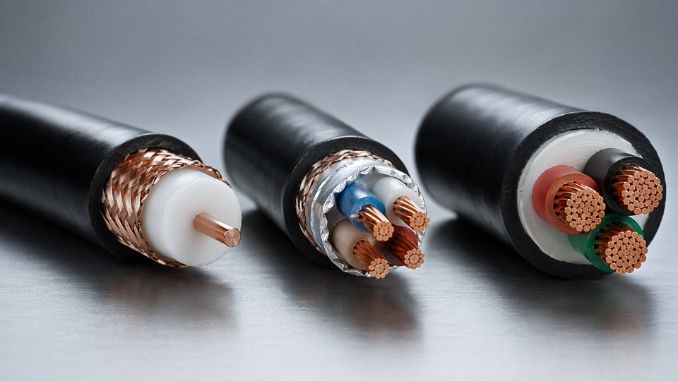
Cut a short sample and look at the cross-section — ideally under a loupe or low-power magnifier. Coax will show a center conductor (solid or stranded), a uniform dielectric layer surrounding it concentrically, then a continuous outer conductor as braid or foil sitting coaxially around the dielectric, then a jacket. The concentricity is the tell. A shielded power or signal cable will show multiple insulated conductors grouped inside the shield, not a single centered conductor with a uniform dielectric wall. If the cross-section looks like a bulls-eye, it’s coax. If it looks like a bundle, it isn’t.
Can one supplier provide both power cables and coaxial cables for a large infrastructure project?
Yes, and for major projects it’s worth actively seeking that consolidation. Managing two separate cable supply chains means two vendor qualification audits, two sets of test documentation, two shipping schedules to coordinate, and twice the exposure to substitution risk on a long build. Manufacturers with genuinely diversified production capacity — Jinda operates five production bases across China covering over 470,000 m² — can produce both product families under a single quality management system and ship against a unified order. For procurement managers handling international infrastructure projects, that simplification has real value: one audit, one set of certifications to verify, one point of contact when a delivery schedule shifts.