Specify “cable wire” in a purchase order without understanding what you’re actually asking for, and you will get whatever the supplier decides to send. That might be a fine-stranded Class 5 flexible conductor when your panel wiring needed a rigid Class 1 bus bar, or a single-wire solid conductor where the application demands repeated flexing — and either mismatch creates real problems fast. Wrong conductor class leads to premature fatigue cracking, termination failures, or code non-compliance that holds up commissioning. At scale, those rework costs and project delays add up to far more than the price difference between conductor types ever would have.
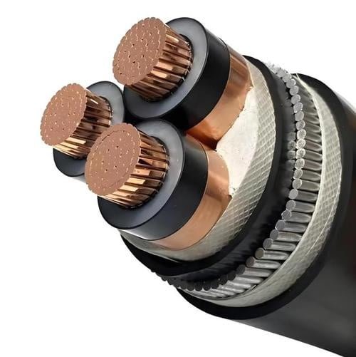
Cable wire refers to the individual metallic conductor strands — most commonly copper or aluminum — that form the current-carrying core of an electrical cable. A cable typically contains one or more of these conductors, each classified by material, cross-sectional area, and stranding configuration. The correct type depends on the application: fixed installation, flexible connection, or continuous flexing service.
What makes this question harder than it looks is that “cable wire” sits at the intersection of material science, mechanical engineering, and international standards — and the answer shifts depending on whether you’re wiring a building, a machine tool, or an offshore platform. The global wire and cable market was valued at roughly USD 226 billion in 2023 and is on track to exceed USD 300 billion by 2030, which tells you just how many industries are making this decision every day, often without fully understanding the options in front of them.
Conductor Materials Decoded: Copper, Aluminum, Alloy, and Specialty Metals
The conductor is where every cable design decision starts — and where most procurement mistakes get made. Choosing the wrong material doesn’t just affect upfront cost; it shows up six months later as voltage drop complaints, failed terminations, or a fire marshal’s report.
Copper: Why It Still Dominates
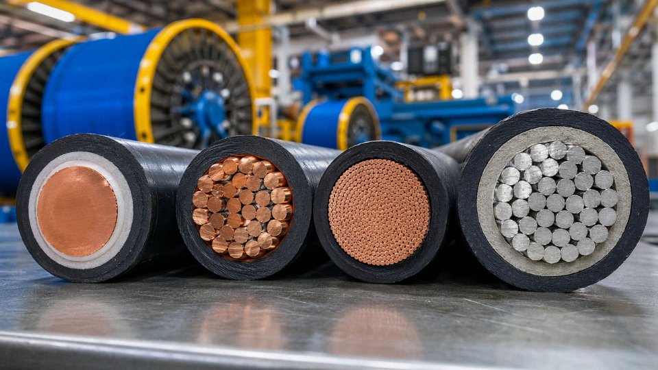
Annealed soft-drawn copper runs at roughly 58 MS/m electrical conductivity and tensile strength in the 200–250 MPa range, though the actual figure depends on temper, drawing reduction ratio, and whether you’re working with oxygen-free (OFC) or electrolytic tough pitch (ETP) rod. That combination of high conductivity, solderability, and flex endurance is why copper shows up in building wiring, automotive harnesses, and any industrial cable that gets flexed repeatedly — think drag chains, robotic arms, or elevator trailing cables. You simply can’t match copper’s bend cycle life with any cheaper alternative at the same cross-section.
Copper is also forgiving at terminations. Aluminum oxidizes aggressively; copper, less so. On a panel build or a junction box where a maintenance electrician is re-torquing lugs every few years, that matters more than the material cost per kilogram.
The downside is weight and price volatility. Copper trades on LME and the spot price swings ±30% or more across a contract cycle — something procurement teams on long infrastructure projects learn to hedge against, or suffer.
Aluminum and the Cross-Section Compensation Rule
Aluminum’s conductivity sits around 35 MS/m, so to carry the same current as a copper conductor, you need roughly 1.6× the cross-sectional area. That sounds like a loss, but aluminum’s density is only 2.7 g/cm³ versus copper’s 8.9 g/cm³. Work through the math on a 500 kV overhead transmission line spanning hundreds of kilometers, and aluminum wins on total installed cost by a significant margin — lighter conductor means lighter towers, wider span capability, and substantially lower material cost per kilometer even after the cross-section upsize.
Overhead ACSR (aluminum conductor steel reinforced) and AAAC (all-aluminum alloy conductor) are the workhorses of transmission infrastructure worldwide for exactly this reason. For large-format power cables — think 630 mm² feeders in a substation or a data center main distribution board — aluminum is increasingly competitive once you account for the full bill of materials, not just the conductor price per meter.
An aluminum conductor must be approximately 1.6 times larger in cross-sectional area than a copper conductor to carry equivalent current.True
This follows directly from the conductivity ratio: copper ~58 MS/m, aluminum ~35 MS/m. The ratio is roughly 1.66×, typically rounded to 1.6× for practical cable sizing, consistent with IEC and NEC sizing tables.
AA-8000 Series Alloy: Not Your Grandfather’s Aluminum Wire
Pure aluminum has a creep problem. Under sustained mechanical load at a bolted lug, it cold-flows, the termination loosens, resistance rises, and you get heat. That failure mode caused real problems in residential wiring decades ago and is part of why aluminum got a bad reputation in branch circuit applications.
AA-8000 series alloys (per ASTM B-800) address this with small additions of iron, silicon, and other elements that improve creep resistance and fatigue life without meaningfully hurting conductivity. North American residential wiring and medium-voltage distribution have been the growth area for this material — it’s gaining acceptance in markets that previously refused aluminum at the distribution level, and the revised NEC provisions in the US reflect that shift.
Copper-Clad Aluminum: Proceed Carefully
CCA puts a copper layer over an aluminum core, nominally offering copper’s surface conductivity at reduced weight and cost. The skin effect argument holds at RF frequencies — for coaxial cable and certain signal applications, CCA performs reasonably well. At power frequencies and high continuous current, though, the aluminum core carries most of the load, and the current-carrying capacity is closer to aluminum than copper.
The real risk is mis-specification. Some CCA products reach the market labeled or packaged in ways that make them easy to confuse with solid copper. In high-current terminations or installations where the conductor cross-section was sized for copper, substituting CCA without recalculating creates an underrated installation. Verify the conductor material explicitly in the purchase specification, not just the cable outer diameter or color code.
Specialty Conductors for Harsh Environments
Tinned copper — copper with a hot-dip or electroplated tin coating — is standard in marine cable and any application where the conductor will see sustained humidity, salt air, or contact with sulfur-bearing insulation compounds. The tin layer prevents the oxidation that would otherwise migrate under the insulation and increase contact resistance over time. In practice, most decent marine cable specs call for tinned conductors as a minimum, not an option.
Silver-plated copper is used in high-frequency signal cables where surface conductivity matters — the skin effect at microwave frequencies means most current flows in the outermost few microns of the conductor, and silver’s slightly higher conductivity versus copper justifies the cost premium in aerospace and telecom applications.
Nickel-plated copper handles the temperature range above roughly 150 °C where tin’s melting point becomes a concern. You’ll find it in furnace wiring, engine bay harnesses, and cables routed near heat sources in industrial equipment. Nickel plate also provides better chemical resistance in aggressive atmospheres.
| Material | Conductivity (MS/m) | Tensile Strength | Density (g/cm³) | Typical Application | Key Standard |
|---|---|---|---|---|---|
| Annealed copper (ETP) | ~58 | 200–250 MPa | 8.9 | Building, automotive, flex industrial | IEC 60228, ASTM B3 |
| EC-grade aluminum | ~35 | 80–120 MPa | 2.7 | Overhead transmission, large power feeders | IEC 60228, ASTM B230 |
| AA-8000 alloy aluminum | ~34–35 | 95–130 MPa | 2.7 | Residential branch circuit, MV distribution | ASTM B-800, UL 44 |
| Copper-clad aluminum | ~40–50 (effective) | Varies | ~3.6–4.5 | RF coaxial, cost-reduction signal cable | Verify per application |
| Tinned copper | ~56–57 | 200–250 MPa | 8.9 | Marine, humid industrial, sulfur-bearing insulation | IEC 60228, UL 83 |
| Silver-plated copper | ~59–61 | 200–240 MPa | 8.9 | High-frequency signal, aerospace | MIL-W-16878 |
| Nickel-plated copper | ~40–45 | 200–250 MPa | 8.9 | High-temp cables above 150 °C, furnace wiring | IEC 60228 |
Conductivity figures for plated conductors reflect the composite; tensile strength depends on temper and wire gauge.
Jinda’s conductor drawing lines process oxygen-free copper rod and EC-grade aluminum rod, with in-line resistance measurement traceable to national metrology standards — so when a batch certificate states a resistivity value, there’s a calibrated instrument record behind it, not just a nominal specification copied from a material datasheet. For procurement teams specifying to IEC 60228 or ASTM, that traceability matters when a project’s inspection regime includes third-party conductor resistance verification on arrival.
Stranding Architecture: Solid, Stranded, and Flexible Conductor Classes Explained
The physical arrangement of individual wires inside a conductor is one of those decisions that looks trivial on a data sheet but bites you hard on the job site — or three years later when a cable fails in a drag chain at 50,000 cycles.
Solid Conductors (IEC 60228 Class 1)
A Class 1 conductor is a single drawn wire. No stranding, no geometry complexity. That simplicity makes it the lowest-cost option per meter, and for fixed wiring in conduit — building circuits, underground ducts, panel board feeds — it is perfectly adequate up to around 16 mm². Above that, a solid rod becomes genuinely difficult to handle during installation; termination into lugs gets ugly fast.
The hard rule: never put a Class 1 conductor in any application that involves repeated movement. One or two flex cycles during installation, fine. A cable routed through a hinged panel that opens twice a day? The wire work-hardens at the bend radius and fractures, sometimes without any visible external damage to the insulation. I have seen this failure mode blamed on “bad cable” when the spec simply called the wrong class.
Stranded Conductors (Class 2): The Workhorse
Class 2 is the standard for power cables across the overwhelming majority of industrial and infrastructure applications — from 1.5 mm² control wiring up through 1,000 mm² and larger transmission conductors. IEC 60228 sets the minimum wire count at 7 individual wires for conductors up to 16 mm², arranged in concentric lay geometry: a central wire surrounded by successive helical layers, each layer wound in the opposite direction to the one beneath it.
The concentric-lay geometry matters because it keeps the conductor round and dimensionally stable under compressive forces during termination. Fill factor — the ratio of conductor metal area to the circle area the conductor occupies — runs roughly 0.75–0.85 for Class 2, depending on cross-section and wire count. That gap matters when you’re sizing conduit fill or calculating heat dissipation in a tight duct bank.
One detail worth knowing: stranded conductors are not identical in DC resistance to a solid conductor of the same nominal cross-section. Each individual wire follows a helical path, so its actual length is slightly greater than the cable run. The correction factor, sometimes called the stranding factor, is typically 1.02 to 1.04 for Class 2. Resistance per unit length follows R = ρL/A, where L here is the effective wire length after accounting for lay angle — so a 50 mm² Class 2 copper conductor will measure slightly higher resistance per meter than a theoretical solid 50 mm² bar. Usually it stays within IEC tolerance, but if you’re doing a precision voltage-drop calculation for a long LV feeder, don’t ignore it.
Flexible Classes 5 and 6
Class 5 and Class 6 exist for applications where the cable moves — continuously, repeatedly, or under tight bend radii. The difference between them is wire diameter: Class 5 uses fine wires bundled in a bunched-lay or bunch-stranded arrangement, while Class 6 goes finer still, with individual wire diameters as small as 0.1 mm, producing a conductor that feels almost rope-like in your hands.
Typical applications for Class 5 include portable power tools, extension leads, and site distribution cables. Class 6 is what you want for welding cables, elevator trailing cables, and robotic drag chains — anything seeing thousands to tens of thousands of flex cycles. The accepted threshold in practice: if the cable will experience more than roughly 1,000 bend cycles across its service life, Class 5 is the minimum. Drag-chain applications in automotive assembly, where cycle counts can reach into the millions, demand Class 6 with the appropriate lay pitch optimized for the specific bend radius.
IEC 60228 Class 6 conductors use individual wire diameters as small as 0.1 mm to achieve the flexibility required for high-cycle moving applications such as robotic drag chains.True
IEC 60228 specifies Class 6 as the finest flexible conductor class, with very fine wire bunching. Wire diameters in the 0.08–0.15 mm range are standard in compliant Class 6 welding and drag-chain cables, confirmed by IEC 60228 Table values and common industry practice.
Sector-Shaped Conductors
In multi-core power cables — three-core or four-core designs for distribution — conductors are often shaped into a sector or “D” profile rather than a round circle. Pack three round conductors together and you get triangular voids between them; replace those with sector-shaped conductors and the overall cable diameter drops by roughly 10–15%, depending on cross-section. Smaller diameter means less insulation material, less armoring, less sheath compound, and meaningfully smaller conduit or duct requirements in large installations. On a 10 km medium-voltage feeder run, that material saving adds up to a number procurement managers notice.
Quality Controls That Actually Matter
Conductor geometry that drifts outside IEC tolerance — lay length too short, wire diameter inconsistent, concentric layers misaligned — causes elevated resistance, hot spots under load, and termination problems. At Jinda’s stranding lines, laser-diameter gauges run inline at each machine, and lay-length verification is checked continuously rather than as a periodic sample. It’s not glamorous process control, but it is what separates cable that passes a factory acceptance test from cable that also performs correctly after five years in the ground.
Insulation and Jacket Materials: How the Wire Is Protected and Why It Matters
The conductor gets most of the attention in cable selection — copper vs. aluminum, stranding class, cross-section. The insulation system is what actually keeps that conductor alive in service. Get it wrong and you’re looking at premature dielectric breakdown, accelerated aging, or a fire event that shuts down a facility for weeks. These aren’t theoretical failure modes; they’re the most common reasons cable replacement projects get triggered ahead of schedule.
PVC: Everywhere, Cheap, and Not Always the Right Call
Polyvinyl chloride remains the dominant insulation compound globally, and for general-purpose wiring in dry-to-moderately-damp indoor environments below 70 °C conductor temperature, it earns its place. It’s cheap, it bonds well to copper and aluminum, and it resists oils and weak acids reasonably well. The problem surfaces the moment there’s a fire. PVC combustion releases hydrogen chloride gas — corrosive, toxic, and damaging to electronics and structure well beyond the immediate burn zone. A single burning PVC cable run in a server room or a transit tunnel can destroy equipment far from the ignition point through HCl condensate alone.
EU RoHS and REACH regulations now restrict certain phthalate plasticizers used in PVC formulations, which matters if you’re supplying equipment into European markets or procuring cables for plant expansions there. Not all PVC is equally restricted — formulation details matter — but “PVC cable” as a generic procurement description is no longer sufficient where compliance documentation is required.
XLPE: The Workhorse at Medium and High Voltage
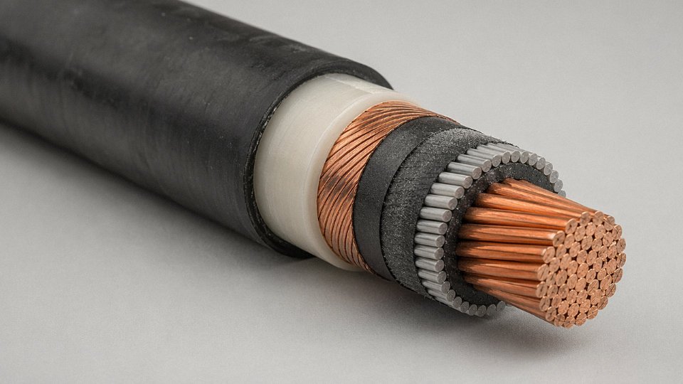
Cross-linked polyethylene has essentially displaced paper-oil insulation for power distribution cables from roughly 1 kV up to 500 kV. The cross-linking process converts thermoplastic PE into a thermoset structure, pushing continuous rated conductor temperature to 90 °C and short-circuit tolerance to around 250 °C. Dielectric strength runs in the range of 18–25 kV/mm depending on compound grade and processing quality — that range matters, because void-contaminated XLPE at the lower end will fail in service at voltages where clean triple-extruded material is completely stable.
At 35 kV and above, the extrusion process becomes genuinely critical. Any micro-voids, contaminants, or eccentricity in the insulation wall are initiation sites for electrical treeing, which eventually causes catastrophic failure. This is why reputable MV/HV cable manufacturers run triple-extrusion — inner semiconductive screen, XLPE insulation, and outer semiconductive screen extruded simultaneously in a clean environment — rather than sequential passes.
XLPE insulation rated at 90 °C continuous allows significantly higher current-carrying capacity than PVC at the same conductor cross-section.True
Higher permissible conductor temperature directly increases the allowable current per IEC 60287 thermal calculations, meaning a 95 mm² XLPE cable can carry more current than the same cross-section with 70 °C PVC insulation under identical installation conditions.
EPR, LSOH, and Silicone: When Standard Compounds Aren’t Enough
Ethylene propylene rubber stays flexible down to around –50 °C and handles ozone, UV, and radiation exposure better than most thermoplastic compounds. Offshore drilling cables, mining trailing cables, and nuclear instrumentation cables almost universally use EPR for this reason. It’s more expensive than XLPE and harder to terminate cleanly, but in those environments there’s no practical substitute.
LSOH (low-smoke zero-halogen, also called LSZH) has become mandatory rather than optional in tunnels, metro systems, airports, public buildings, and data centers across most jurisdictions following fire code revisions over the past 15–20 years. IEC 60332-3 flame spread testing is the standard benchmark. The tradeoff is mechanical toughness — LSOH compounds are generally stiffer and more notch-sensitive than PVC, so installation in conduit requires more care.
Silicone rubber sits at the extreme end: rated from –60 °C to roughly +180 °C continuous, with some specialty grades pushing higher. It’s the go-to for furnace door cables, aerospace wiring, and any application where the cable runs through sustained radiant heat. Cost is significantly higher than other options — silicone cable typically runs 3–6× the price of equivalent PVC construction depending on cross-section and market conditions — so it gets specified only when the temperature envelope genuinely demands it.
Outer Jacket Selection: Matched to the Mechanical Environment
The insulation handles the electrical stress. The outer jacket handles everything else — abrasion, chemical splash, UV, flexing cycles, rodent damage in some installations. PVC ST2 and ST3 grades cover most general industrial applications. Polyurethane (PUR) jacketing is the standard choice for drag-chain cables in automated machinery because it maintains flexibility through millions of flex cycles without cracking; standard PVC hardens and splits under that kind of repeated bending. Polyethylene works well for direct burial and aerial self-supporting applications where UV resistance and moisture blocking matter more than flexibility. CSPE (Hypalon) is worth specifying in chemical plant environments where jacket exposure to aggressive solvents or oxidizing agents is routine — it holds up where PVC and PUR would swell or degrade.
One practical note: jacket and insulation compound compatibility with the termination hardware matters more than many procurement specs acknowledge. PUR-jacketed cables, for instance, require different gland materials than PVC-jacketed equivalents; using the wrong gland in an oil mist environment defeats the purpose of specifying PUR in the first place.
Insulation Selection Reference
| Insulation / Jacket | Continuous Temp Rating | Typical Voltage Range | Fire Performance | Primary Standards |
|---|---|---|---|---|
| PVC | 70 °C | Up to 1 kV | Flame retardant; HCl fumes | IEC 60227, UL 83 |
| XLPE | 90 °C (250 °C s/c) | 1 kV – 500 kV | Better than PVC; halogenated | IEC 60502, IEC 60840 |
| EPR | 90 °C | Up to 35 kV typical | Good; halogen-free variants available | IEC 60245 |
| LSOH / LSZH | 70–90 °C | Up to 35 kV | Low smoke, zero halogen; IEC 60332-3 | IEC 61034, EN 50525 |
| Silicone Rubber | –60 °C to +180 °C | Low voltage typical | Self-extinguishing; low smoke | IEC 60245-4, UL 508 |
| PUR (jacket) | –40 °C to +80 °C | — | Moderate | UL 62, VDE 0282 |
| PE (jacket) | –40 °C to +70 °C | — | Slow burning | IEC 60811 |
| CSPE / Hypalon | –40 °C to +90 °C | — | Good chemical resistance | UL 44 |
Jinda’s dedicated XLPE triple-extrusion lines process conductor feed through a clean-room environment before and during extrusion, which is what makes the difference for cables rated 35 kV and above. Void-free insulation at that voltage level isn’t a quality-assurance checkbox — it’s the difference between a 30-year service life and a premature failure event during the first overload cycle.
Cable Wire Classification by Application: Power, Control, Instrumentation, and Data
Understanding what a cable does is usually the fastest route to specifying what it is. Voltage class, signal type, environment, and regulatory jurisdiction each pull the construction in different directions — and conflating categories at the procurement stage is how projects end up with undersized screens, inadequate fire performance, or data cables that degrade signal integrity before the panel is even commissioned.
Low-Voltage Power Cables (Up to 1 kV, IEC 60502-1)
The fixed wiring backbone of most commercial and industrial buildings runs on LV power cable — NYY (PVC-insulated, PVC-jacketed, copper conductor), N2XY (XLPE-insulated, copper), and NAYY (PVC, aluminum conductor) are the configurations that dominate European-influenced markets. Cross-sections run from roughly 1.5 mm² up to 400 mm² or beyond for main feeders. XLPE-insulated variants handle continuous conductor temperatures around 90 °C versus roughly 70 °C for PVC, which matters when you’re running cable in a tightly packed trunking system in summer — ambient temperature derating isn’t academic at that point.
Medium-Voltage Power Cables (1 kV–36 kV, IEC 60502-2)
Screen design is where MV cable separates itself from the LV world. Copper tape screen, copper wire screen, or a combined arrangement all serve to equalize the electric field around the insulation, but their current-carrying capacity under fault conditions differs meaningfully — copper wire screen handles short-circuit energy better, while tape screen is lighter and cheaper for straight runs with no expected fault contribution. The real quality gate at this voltage class is partial discharge (PD) testing: a credible manufacturer holds PD below 10 pC at 1.5× operating voltage. Numbers above that threshold indicate voids or contaminants in the XLPE that will eventually erode to failure, sometimes years after installation.
Partial discharge levels below 10 pC at 1.5× operating voltage are the accepted quality threshold for medium-voltage XLPE cables under IEC 60502-2.True
IEC 60502-2 and associated test standards specify PD extinction voltage and permissible PD levels during type and routine testing; 10 pC is the widely cited routine-test limit used by utilities and industrial specifiers.
High-Voltage and Extra-High-Voltage Cables (Above 66 kV, IEC 62067)
At transmission voltages, the insulation is no longer a commodity item. HV and EHV cables use high-purity XLPE applied in a triple-extrusion head — inner semi-conductive screen, insulation, and outer semi-conductive screen extruded simultaneously to eliminate interface contamination. Any particulate or moisture inclusion at this level becomes a field enhancement site. Jinda’s manufacturing capability extends to 220 kV projects, which puts the production process firmly in the category where cleanliness protocols in the extrusion hall resemble a pharmaceutical environment more than a typical cable plant.
Control Cables (IEC 60227 / IEC 60245 Family)
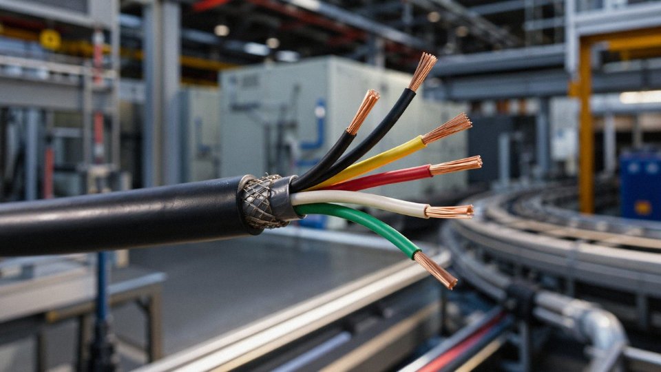
Control cable is the nervous system of an automated plant — multi-core, small cross-sections typically in the 0.5–10 mm² range, carrying switching commands and interlock signals rather than load current. Screened versions (overall braid or foil) matter in environments with heavy VFD or contactor switching; without shielding, induced noise on a 24 V DC control loop can produce spurious trips that take a maintenance team days to diagnose. The cable is cheap. The downtime isn’t.
Instrumentation Cables
Where control cable carries commands, instrumentation cable carries measurements — 4–20 mA loops, thermocouple signals, HART, sometimes low-level millivolt outputs from load cells. Individual shielding (IS) on each pair plus an overall shield (OS) is the standard for noise-sensitive analog signals in DCS environments. Low-capacitance insulation — polyethylene rather than PVC where budget allows — preserves signal integrity over long runs, typically anything over 200–300 m to a marshalling panel. Twisted pairs or quads reduce common-mode interference pickup; the twist pitch is not a trivial detail.
Data and Communication Cables
Cat5e handles most structured cabling up to 1 Gbps at 100 m; Cat6A is the current default for new industrial installations targeting 10 Gbps. Coaxial RG-series cable remains standard for RF and certain industrial video applications. Fiber-optic hybrid cables — combining optical fibers and copper power conductors in a single jacket — are increasingly common in CCTV infrastructure and distributed control where running two separate cables is impractical. Worth clarifying for purchasing: in a fiber-optic cable, the “wire” element is the aramid or steel strength member, not the signal carrier. Specifying the wrong pulling tension or bend radius because someone treated it like copper will fracture fibers invisibly.
Specialty Application Cables
Fire-resistant cables to IEC 60331 must maintain circuit integrity for 90 minutes at 830 °C — verified by test, not extrapolated. For rail applications, EN 50264 adds halogen-free flame retardant requirements to avoid toxic smoke accumulation in tunnels. Submersible pump cables live permanently in water and need robust waterblocking and pressure-rated jackets. Wind-turbine tower cables are designed for continuous torsional cycling — standard cable fails here through insulation cracking at the conductor surface within a relatively short service life. Solar PV DC cable to EN 50618 / IEC 62930 handles up to 1.5 kV DC with UV and ozone resistance, since it sits on a roof or in a ground array for 25-plus years.
Jinda’s product range covers all of these categories, with UL, CE, CCC, and SASO certifications that map to the major import requirements across North America, Europe, China, and Gulf Cooperation Council markets respectively.
Key International Standards and How They Govern Cable Wire Construction
Standards aren’t paperwork formalities. Get them wrong on a project spec, and you’re looking at failed inspections, re-procurement delays, and in some cases genuine safety liability. Understanding which standard applies where — and what it actually requires — is what separates a defensible cable specification from one that unravels during factory acceptance testing.
The IEC Baseline
IEC standards form the technical foundation for most international projects outside North America. IEC 60228 defines conductor classes — the same classes covered in the stranding section — and sets resistance limits per conductor cross-section, which directly affects voltage drop calculations. IEC 60502 covers extruded solid dielectric power cables from 1 kV up through 30 kV, specifying insulation thickness tolerances, screen construction, and test requirements. In practice, IEC 60502-1 handles the 1–3 kV range while IEC 60502-2 covers medium voltage; specifying the wrong part is a surprisingly common error in early-stage procurement.
IEC 60227 and IEC 60245 address PVC-insulated and rubber-insulated cables respectively, mostly for fixed wiring and flexible cords. IEC 60332 covers fire performance — a family of tests ranging from single-cable flame propagation (IEC 60332-1) to large-scale vertical tray burn tests (IEC 60332-3), which matter enormously for cable routing in tunnels, data centers, and offshore platforms. IEC 62893 is the newer addition, governing EV charging cables; it’s already a procurement requirement for charging infrastructure projects across Europe and increasingly in the Middle East.
UL Requirements for North American and US-Spec Projects
Any cable going into a North American facility, or into a project where the EPC contractor follows NEMA/NEC requirements, will need UL listing. UL 44 covers thermoset-insulated cables (XLPE, EPR), UL 83 covers thermoplastic types (THHN, THWN), and UL 1277 covers industrial tray cables — a category used heavily in petrochemical and industrial plant wiring. The wrinkle is that US engineering contractors frequently carry UL requirements into projects in Southeast Asia, the Middle East, and Latin America even when local codes don’t strictly demand it. If you’re supplying into EPC-driven projects, assume UL may be asked for regardless of geography.
BS, CENELEC, and the European Harmonized Framework
Projects in the UK, much of the Middle East, and parts of Africa often reference BS 6346 or the EN 50525 series. CENELEC’s harmonized designation system assigns a standardized code to each cable type across member countries, which means a HAR-marked cable sold in Germany carries the same technical requirements as one sold in the Netherlands. For procurement managers comparing European-sourced and Asian-sourced cable, this harmonization is useful — it gives you a common technical reference point for comparing bids.
National Standards and Project-Specific Compliance
GB/T 12706 is the Chinese national standard for PVC and XLPE power cables, closely aligned with IEC 60502 but with some differences in test methods and dimensional tolerances. IS 7098 covers XLPE cables for the Indian market, AS/NZS 1125 applies in Australia and New Zealand, and SASO governs Saudi projects — a requirement that catches some exporters off guard the first time they bid into the Gulf. Jinda holds certifications across several of these national standards specifically to support project-specific compliance without requiring customers to run separate qualification rounds.
Reading a Cable Designation Code
Take N2XSY 3×150 mm² 12/20 kV as a worked example. “N” indicates the cable meets German VDE standards (a common prefix in European-influenced specs). “2X” means XLPE insulation. “S” denotes a copper wire screen. “Y” indicates a PVC outer sheath. “3×150 mm²” is three conductors, each 150 mm² cross-section. “12/20 kV” gives the conductor-to-ground voltage and conductor-to-conductor voltage respectively. Every character is load-bearing. Misreading “S” as a solid screen when the project requires a corrugated metallic screen, for instance, will fail type testing.
Routine Tests, Type Tests, and Why the Distinction Matters
Most cable suppliers can produce routine test results — conductor resistance, voltage withstand, insulation resistance — because these are run on every production length. Type tests are different. Partial discharge testing, bending tests, hot-set elongation for XLPE — these are run once on a representative sample to prove the design itself is sound, and they require accredited lab equipment most factories don’t own in-house.
A cable supplier's in-house routine test report is sufficient proof of compliance for medium-voltage cable procurement.False
Routine tests verify production consistency but do not validate the cable design. Medium-voltage cable procurement should require type test reports from an accredited third-party laboratory such as KEMA, SGS, or TÜV, confirming the specific construction meets the applicable standard.
Buyers should request type test reports from accredited labs — KEMA, TÜV, SGS are the names that carry weight with most project engineers — and confirm the test report was issued on the exact construction being quoted, not a similar product. A type test on a 95 mm² cable does not automatically cover a 150 mm² cable of nominally similar design.
Jinda operates in-house testing laboratories calibrated under CNAS accreditation and partners with KEMA, SGS, and TÜV for type testing on export cables. That separation — internal routine testing plus external type-test verification — is the right structure. Any supplier who claims their in-house lab is sufficient for type tests on medium-voltage cable deserves a follow-up question.
How to Read a Cable Wire Datasheet: Cross-Section, Voltage Rating, and Current Capacity
A cable datasheet looks straightforward until you’re in a procurement dispute over why a “95 mm² cable” is tripping protection relays it shouldn’t. Most misreads come from treating nominal values as absolute physical measurements. They aren’t.
Nominal Cross-Section Is a Resistance Specification, Not a Ruler Measurement
The figure printed as “1.5 mm²” or “70 mm²” on a datasheet is a nominal designation tied to a maximum DC resistance per kilometer at 20 °C — not the geometrically measured copper area you’d get from a micrometer. IEC 60228 is the governing document. For a 1.5 mm² Class 2 stranded copper conductor, the resistance limit is ≤12.1 Ω/km. A 70 mm² conductor must fall at or below 0.268 Ω/km.
Why does this matter in practice? Because a marginal manufacturer can use slightly undersized wire draws and still pass a visual or diameter check. The resistance test catches them. When auditing a new supplier, always request conductor resistance test certificates, not just dimensional reports. The two are not the same document.
The nominal cross-sectional area of a cable conductor (e.g., 70 mm²) is defined by IEC 60228 through a maximum DC resistance per unit length at 20 °C, not by physically measuring the conductor's cross-sectional area.True
IEC 60228 explicitly defines conductor classes by maximum resistance values per kilometre at 20°C. The nominal cross-section is a conventional designation used to identify conductor size; actual measured area can differ slightly from the nominal value while still complying with the standard.
Voltage Rating: U₀/U Is Not One Number
The notation 0.6/1 kV on a datasheet means the cable is rated for 0.6 kV from conductor to earth (U₀) and 1 kV conductor-to-conductor (U). Non-specialist buyers — and occasionally junior engineers — read “0.6/1 kV” and assume the cable tops out at 0.6 kV. That misread results in either over-specifying a more expensive MV cable or, worse, applying it in a system where the actual phase-to-phase voltage exceeds the U rating. In a 400 V TN-S distribution system, a 0.6/1 kV cable is correctly rated; in an ungrounded IT system where phase-to-earth fault voltage can approach the phase-to-phase value, you need to reconsider U₀.
Ampacity: The Rated Number Assumes Conditions You Probably Don’t Have
A 95 mm² copper XLPE cable might carry 250 A in free air at 30 °C ambient. Put five of those cables in a conduit, buried at 0.7 m in soil with thermal resistivity above 1.5 K·m/W, at 40 °C ambient, and you’re realistically looking at something in the 160–185 A range after applying grouping, temperature, and soil resistivity derating factors from IEC 60364-5-52 and IEC 60287. The exact derated figure depends on your specific installation geometry — there’s no single correct answer without working the calculation.
Skipping the derating math and sizing on the “free air” number is one of the more common causes of premature cable aging and unexpected tripping on new industrial installations. Insulation degrades faster above rated temperature; once XLPE or PVC exceeds its continuous temperature limit, service life shortens non-linearly.
Short-Circuit Rating: The Formula Procurement Teams Often Ignore
The adiabatic equation I²t = k²S² defines the short-circuit current a conductor can survive without damage. For copper with PVC insulation, k = 143; for XLPE copper, k = 176. A 70 mm² Cu XLPE cable protected by a relay with a 1-second clearing time can handle roughly √(176² × 70²) ≈ 12,320 A short-circuit current. If your fault level is higher and clearing time is longer, that cable is undersized for protection coordination — even if it’s perfectly adequate thermally under normal load.
This parameter is especially relevant when specifying cables feeding MV switchgear panels or motor control centers where fault currents can be substantial.
AC Parameters for Long Runs and Harmonic-Heavy Plants
On runs under roughly 500 m at 50/60 Hz, capacitance and inductance rarely change the engineering story much. On longer distribution cables — say, 2–5 km underground feeders — capacitive charging current eats into useful ampacity, and the reactive power contribution needs to factor into power factor correction planning. In plants with significant VFD loading, harmonic currents increase the effective AC resistance above the DC value (skin and proximity effects), so the AC resistance figure on the datasheet, not just the DC resistance, becomes the number to use for voltage drop calculations.
Minimum Bending Radius: The Spec That Gets Ignored During Installation
Armored cables typically carry a minimum bending radius of 12–15 times the overall cable diameter for installation bending; some flexible constructions permit tighter radii, but that’s the exception. Exceeding the limit during pulling or at a conduit entry compresses the armor wires unevenly, deforms the conductor, and can micro-crack the insulation — none of which is visible from outside without a partial discharge test or time-domain reflectometry. Damage shows up later as insulation failure, sometimes months after commissioning.
Worked Comparison: NYY vs N2XY at 0.6/1 kV, 70 mm² Copper
| Parameter | 70 mm² Cu PVC (NYY) | 70 mm² Cu XLPE (N2XY) |
|---|---|---|
| DC resistance at 20 °C | ≤0.268 Ω/km | ≤0.268 Ω/km |
| Max. conductor temp | 70 °C | 90 °C |
| Typical ampacity (free air, 30 °C) | ~200–215 A | ~240–255 A |
| k factor (short circuit) | 115 (conductor) | 143 (conductor) |
| Approx. outer diameter | 26–29 mm | 25–28 mm |
| Approx. weight | 3,500–4,000 kg/km | 3,200–3,600 kg/km |
| Typical price premium (XLPE vs PVC) | baseline | +8–18% depending on wall thickness and market copper price |
The XLPE variant runs cooler at equivalent load, tolerates higher short-circuit energy, and is lighter — meaningful when you’re pulling through long conduit runs. The PVC version remains widely used where the lower upfront cost and simpler termination practice outweigh the thermal headroom advantage. Neither is universally “better”; the right call depends on ambient conditions, fault level, and how aggressively the circuit will be loaded.
Armoring, Shielding, and Screening: When the Wire Needs Extra Protection
Specifying protection layers is where a lot of cable purchases go wrong in both directions. Over-specify and you’re paying 30–40% more per meter for armor or shielding that the installation never needed. Under-specify and you’re pulling a damaged cable out of a trench eighteen months after commissioning. Neither outcome is acceptable.
Steel Wire Armoring (SWA)
Galvanized steel wires — typically 0.8 mm to 3.15 mm diameter depending on cable OD — are applied helically over the inner sheath. This is the workhorse of direct-burial power distribution. SWA handles tensile loads during pulling, resists rodent damage, and takes incidental mechanical impact reasonably well. It adds roughly 15–25% to cable weight (heavier at larger conductor cross-sections) and can carry pulling tensions that would destroy an unarmored cable in a long conduit run. Stainless steel wire is specified instead of galvanized where soil chemistry is aggressive — coastal ground, industrial effluent zones — though it costs noticeably more and is harder to terminate cleanly.
Steel Tape Armoring (STA)
Two overlapping flat steel tapes wound in opposite directions. Crush resistance is good; tensile strength is not. STA suits buried installations where mechanical hazard is low and where the cable route is horizontal with no significant vertical sections. Don’t use it for riser cables or any run with a free-hanging vertical drop — the tape construction simply isn’t built for sustained longitudinal tension. Cost is lower than SWA, which makes it attractive for urban duct installations where physical protection is mainly against compaction loads from above-grade traffic.
Aluminum Wire Armoring (AWA) — The Detail That Trips People Up
Single-core cables carrying AC current generate a longitudinal magnetic field. If you armor them with steel wire, you create a shorted turn around that field, which induces circulating currents in the armor. On larger conductors — roughly 95 mm² and above is where it becomes practically significant, though the threshold depends on load current — those circulating currents generate heat. Enough heat, over time, to cause thermal degradation of the inner sheath and eventual failure.
Steel wire armoring on large single-core AC power cables can cause thermal failure through induced circulating currents in the armor.True
Steel is ferromagnetic. On single-core AC cables, the armor forms a closed magnetic circuit around the conductor, inducing eddy and circulating currents proportional to load current. IEC 60502 and engineering practice consistently flag this; non-magnetic armoring (AWA or STA) is required for single-core applications above certain current levels.
Aluminum wire armoring is non-magnetic. It provides the mechanical protection without the electromagnetic problem. This is not obscure knowledge, but it gets missed on projects where the cable schedule is put together by someone who specifies SWA out of habit.
Copper Tape and Wire Screens on MV/HV Cables
On medium- and high-voltage cables, the metallic screen does three things simultaneously: it controls the radial electric field geometry around the conductor, it provides a return path for earth-fault current, and it contains partial discharge activity within the insulation system. The screen cross-section matters enormously. Size it to the project’s earth-fault current magnitude and the clearing time of the upstream protection relay. A screen sized for 1-second clearance will be destroyed in a system where the relay actually operates in 3 seconds under certain fault conditions. This is a protection coordination question as much as a cable question — get the fault level and clearing time from the protection engineer before you write the cable spec.
Electromagnetic Shielding for Instrumentation and Control Cables
Individual pair or triad shielding using aluminum-foil/polyester (AL/PET) tape with a drain wire is the standard for instrument cables in process plant environments. It’s cost-effective and handles high-frequency interference well enough for most 4–20 mA and thermocouple circuits. Overall shielding adds a second layer of protection against lower-frequency interference picked up along the cable run.
Variable-frequency drive environments are a different problem. VFDs generate common-mode noise across a wide frequency spectrum, and AL/PET tape shielding alone is often inadequate because the foil shield has coverage gaps at the overlap seam. Copper braid — typically 85–95% optical coverage — provides 360° contact and handles the high-frequency components that VFD noise produces. Running unshielded or foil-only instrumentation cables near VFD output conductors in a shared tray is one of the more reliable ways to introduce phantom signals into a control system.
Corrugated Aluminum Sheath
Used on EHV and some HV cables for long submarine or critical underground routes, a corrugated aluminum sheath is a hermetic moisture barrier — it prevents water migration into the insulation over decades of service. The corrugation allows bending flexibility that a smooth tube would not. It also functions as the earth screen and can carry significant fault current. The trade-off is termination complexity and cost; this construction is not appropriate for routine distribution projects, but for a long offshore link or a critical urban EHV circuit, the long-term moisture protection justifies it.
Choosing the Right Layer
The decision follows a logical sequence. Assess mechanical hazard first — that determines whether you need SWA, STA, AWA, or nothing. Then check whether the cable is single-core or multi-core on an AC system, which may force you from SWA to AWA or STA. Then evaluate the EMI environment: a clean power distribution circuit needs no electromagnetic shielding; a VFD motor feeder or instrument cable running near high-power switching equipment may need copper braid. Finally, consider moisture ingress risk over the cable’s expected service life, which is where corrugated aluminum sheath enters the picture. Each layer adds cost and installation complexity, so the specification should be driven by what the installation actually demands — not by a conservative reflex to specify everything available.
Common Cable Wire Failures: Root Causes, Detection Methods, and Procurement Safeguards
Cable failures rarely announce themselves. More often, a 15-year-old installation starts tripping protection relays intermittently, or a new cable run fails its hipot test on commissioning day — and the root cause traces back to something that could have been caught at the factory gate, or even at the procurement stage. Understanding the failure modes specific to cable wire construction is arguably more useful than knowing the specifications themselves.
Conductor Resistance Out of Tolerance
The most common non-conformance in commodity cable, and also the easiest to miss on a visual inspection. An undersized conductor — say, a nominal 35 mm² cross-section that measures closer to 31–32 mm² at the actual metallic area — will show elevated DC resistance that pushes operating temperature up during load, accelerates insulation aging, and eventually trips thermal protection at currents the cable is supposed to handle. Low-purity copper (below the ~99.9% required for Class A soft-drawn wire) does the same thing even at the correct geometry.
IEC 60228 resistance limits are the first acceptance criterion you should apply. A routine DC resistance test costs almost nothing and takes minutes per drum. Jinda’s internal rejection rate on conductor resistance non-conformance sits below 0.2% across production runs — which is a useful benchmark when evaluating a new supplier’s process capability claims.
Insulation Voids and Contaminants in XLPE
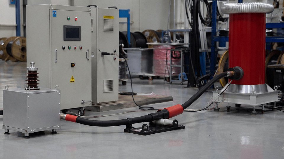
This one is insidious because the cable can pass a simple power-frequency withstand test and still be carrying the seeds of a premature failure. Voids form when XLPE isn’t properly degassed after crosslinking, or when conductor contamination or an extrusion line temperature excursion disrupts the melt. Under operating voltage, partial discharge activity begins in the void, eroding the dielectric from the inside out.
The correct detection method is partial discharge testing at 1.73 U₀ per IEC 60502-2. Cables with voids that survive factory hipot tests typically fail in service within roughly 2–5 years — faster in hot, humid environments or where load cycling is severe. If you’re buying medium-voltage cable and your supplier can’t produce partial discharge test records, that’s a hard stop.
Eccentricity and Insulation Below Minimum Wall Thickness
Insulation that’s geometrically off-center doesn’t reduce average wall thickness — it reduces minimum wall thickness, and impulse withstand is governed by the minimum, not the average. A cable can meet average thickness requirements on a datasheet while having a thin zone that will break down under a switching surge. Production spark testing catches gross eccentricity during extrusion. Cross-section measurement on the finished cable — done properly, not just a caliper on the outside — is the QC step that confirms it.
Armor Wire Corrosion
Galvanized steel armor is tested to coating weight minimums under BS EN 10257 or ASTM A475 depending on the specification. Below those minimums, corrosion in saline soil or acidic industrial ground can destroy the armor layer in under five years. Visual inspection of the armor wire surface tells you almost nothing useful. Request the zinc coating weight test certificates, and check that they’re traceable to an accredited lab — not just a one-line note on the factory’s own letterhead.
Jacket Adhesion Failure in Thermally Cycled Environments
In outdoor installations or anywhere the cable sees wide daily temperature swings, poor adhesion between the jacket and underlying layers allows the jacket to delaminate gradually. Water then migrates to joints and terminations — the most vulnerable points in any cable system. Peel adhesion testing and IP rating cycling per IEC 60529 are both relevant here. This failure mode is especially common in lower-cost cables where the jacket compound was swapped for a cheaper blend without updating the production qualification data.
Counterfeit and Non-Compliant Cable
Copper-clad aluminum (CCA) conductor sold as pure copper is an ongoing problem in several procurement markets, particularly in spot-buy scenarios where price pressure is high and traceability is weak. The conductor looks identical on a cut end without testing. Practical safeguards that don’t require lab equipment: weigh a one-meter sample against the published cable weight per meter — CCA conductors run roughly 30–40% lighter than solid copper for the same cross-section, depending on the cladding ratio. Measure conductor resistance against the IEC 60228 table. Ask for original factory test certificates that include the issuing lab’s accreditation number. If the supplier can’t produce those within a reasonable timeframe, the risk profile of that procurement is higher than the unit price suggests.
Jinda operates under ISO 9001:2015 certification with 100% on-line conductor resistance testing across production lines, and offers customer witness testing at its Shandong production bases.True
These are verifiable quality system credentials and manufacturing practices standard for a serious cable manufacturer; witness testing in particular is a concrete, auditable offer rather than a marketing claim.
The broader point is that quality assurance in cable procurement is not just about approving a sample. It’s about understanding what tests mean, which ones are mandatory versus optional, and where in the production process each defect originates — so you can ask the right questions before you sign the purchase order, not after the first fault report comes in from site.
Selecting the Right Cable Wire for Your Project: A Practical Decision Framework
By the time you’ve worked through conductor material, stranding class, insulation compound, armoring, and standards compliance, the actual procurement decision can feel like it’s buried under a pile of engineering constraints. It doesn’t have to be. A sequential checklist, applied honestly, will get you to a defensible purchase order without backtracking.
Step 1 — Define the Electrical Duty First
Start with the numbers that are non-negotiable: system voltage expressed as U₀/U (phase-to-earth / phase-to-phase), the continuous load current, the prospective short-circuit current, and operating frequency — 50 Hz, 60 Hz, or DC. These four parameters fix your conductor material shortlist and set the floor on cross-section. Skipping this step and guessing a size is how projects end up with cables that are thermally marginal under full load, or that fail the short-circuit withstand test during commissioning. Copper handles higher current density per mm² than aluminum and is the default for anything below roughly 35 mm² simply because jointing aluminum at small cross-sections in distribution panels is messy and error-prone.
Step 2 — Derate Before You Finalize Cross-Section
A conductor’s rated ampacity assumes specific reference conditions — usually 30 °C ambient air, a single cable, unconstrained airflow. Real installations almost never match that. If you’re laying a bundle of 12 cables in a tray in a boiler room running at 45 °C ambient, your effective carrying capacity can drop by 30–40% relative to the rated figure, depending on grouping factor and ambient correction. Apply IEC 60287 for buried routes (soil thermal resistivity matters enormously — dry sandy soil and saturated clay behave very differently) and IEC 60364-5-52 tables for above-ground installations. Size the conductor on the derated figure, not the catalog rating. One size up costs a little more upfront; a thermal failure mid-project costs a lot more in every direction.
Step 3 — Match Construction to the Physical Environment
Direct burial in aggressive soil means steel wire armor (SWA) or steel tape armor (STA) as a minimum — do not skip armor and rely on conduit alone if there is any realistic chance of mechanical damage during future groundworks. Moving machinery connections need Class 5 or Class 6 flexible conductors with a polyurethane (PUR) jacket, which resists both abrasion and the oils that kill standard PVC in weeks. Marine and offshore applications call for tinned copper conductors (tin delays corrosion at the wire surface), EPR insulation for heat and ozone resistance, and double armor where there’s any wave or handling load. Chemical plant environments deserve serious attention to jacket chemistry — CSPE holds up where PVC softens and cracks, and an LSOH compound with an oil-resistant outer layer is worth specifying even if it costs 15–25% more per meter.
Step 4 — Nail the Fire Performance Requirement in Writing
This step gets skipped or vaguely specified more often than it should. IEC 60332-1 covers a single cable’s flame propagation. IEC 60332-3 applies to bunched cables in tray installations — the test is meaningfully harder and the failure mode in a real fire is completely different. IEC 60331 tests circuit integrity under fire, essential for emergency power and fire alarm circuits. EN 50200 and EN 50266 apply to rolling stock and rail installations. Specify the exact standard by number in the purchase order, not just “fire-rated cable.” A supplier who quotes without acknowledging which test regime applies is a risk.
Step 5 — Verify Standards and Certifications Formally
List every applicable standard on the material requisition — IEC, NEC, BS, or local code as the project demands. Then request type test certificates from CNAS- or ILAC-accredited testing laboratories, not internal factory test reports. Country-of-origin certificates matter on public tenders and in jurisdictions with import duties or trade compliance requirements; confirm this before the purchase order is raised, not at customs clearance.
Type test certificates from CNAS/ILAC-accredited laboratories provide independent verification of cable performance against declared standards, whereas factory test reports are self-assessed and carry no third-party assurance.True
CNAS (China National Accreditation Service for Conformity Assessment) and ILAC (International Laboratory Accreditation Cooperation) mutual recognition arrangements ensure that accredited lab results are internationally recognized, distinguishing them from supplier-issued documentation.
Step 6 — Evaluate Supplier Capability Beyond Price
Production capacity in meters per day matters when your project schedule has a fixed commissioning date. Ask about standard drum lengths available — a mismatch between drum length and your cable run lengths generates wasteful offcuts and extra joints. Confirm ocean-freight export packing standard; moisture ingress into a cable drum during a six-week sea voyage is a real problem, not a theoretical one. Jinda supplies standard export wooden drums with ocean-freight packaging including desiccant, and can work to EXW, FOB, or CIF Incoterms depending on the buyer’s logistics preference — which matters when you’re coordinating delivery into a site with a narrow installation window.
Step 7 — Calculate Total Cost of Ownership, Not Just Cable Price
The cheapest cable per meter is almost never the lowest total project cost. A smaller conductor cross-section saves on material but increases resistive losses — ΔP = I²R per kilometer — over the cable’s service life, which typically runs 25–40 years in fixed installations. Heavier armoring increases installation labor, sometimes significantly in cable tray work where the crew is handling coils all day. Factor the probability and cost of early replacement: a cable that fails at year 8 in a buried run costs excavation, materials, and downtime, which typically dwarfs any upfront saving. Run the numbers with realistic load profiles and local electricity costs before signing off on a cross-section that’s technically compliant but economically marginal.
| Decision Factor | Under-Specified Risk | Over-Specified Cost |
|---|---|---|
| Conductor cross-section | Thermal failure, voltage drop | Excess copper/aluminum spend |
| Armor type | Mechanical damage, moisture ingress | Weight, labor, drum size |
| Fire performance class | Code violation, liability | Premium per meter |
| Flexibility class | Fatigue cracking in service | Slightly higher unit cost |
| Insulation compound | Chemical attack, premature aging | Marginal upfront premium |
The framework is linear for a reason — each step narrows the options for the next. Skip one, and you’re guessing somewhere downstream.
Frequently Asked Questions About Cable Wire
What is the difference between a wire and a cable?
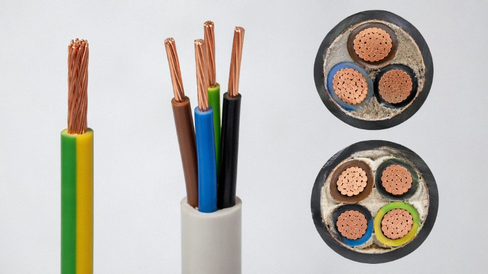
A wire is a single conductor — one solid or stranded element, which may or may not carry its own insulation. A cable is an assembly: one or more insulated conductors, plus whatever additional layers the application demands — bedding, armor, an outer jacket, shielding. In everyday procurement language, “cable wire” usually refers to the conductor element itself sitting inside that finished assembly, but the phrase gets used loosely enough that it’s worth confirming with your supplier exactly what they mean. On a plant floor, the distinction matters when you’re sourcing replacements or writing a bill of materials. Specifying “wire” when you need a multi-core cable is the kind of mismatch that stalls a project.
Is copper or aluminum better for cable wire?
Neither is universally better — and anyone who tells you otherwise hasn’t priced a large MV cable installation lately. Copper runs roughly 60–65% of all conductor volume globally, and for good reason: higher conductivity means a smaller cross-section for the same current, which saves conduit space and simplifies terminations. For industrial panels, motor feeds, or anywhere the cable routing is tight, copper is usually the defensible choice.
Aluminum makes economic sense once you’re looking at large cross-sections — 95 mm² and above is a common threshold, though it depends on copper spot pricing at the time of purchase — and particularly for overhead distribution lines or long direct-buried feeders where weight and cost per ampere-meter both favor the lighter metal. The real calculation is total installed cost: aluminum requires larger cross-sections (roughly 1.6× copper for equivalent ampacity), compatible compression lugs, and anti-oxidant compound at terminations. Get those details right and aluminum pencils out well. Miss them and you get high-resistance joints and callbacks.
What does 0.6/1 kV mean on a cable label?
The designation follows IEC 60502 notation. U₀ = 0.6 kV is the rated voltage from any conductor to earth; U = 1 kV is the rated voltage between any two conductors. In practice this means the cable is designed for low-voltage systems operating up to 1,000 V AC phase-to-phase — your standard industrial and commercial power distribution range. Don’t confuse this with the cable’s impulse withstand or test voltage, which will be higher.
What is XLPE insulation and why is it used?
XLPE — cross-linked polyethylene — is a thermoset, meaning the cross-linking process creates a three-dimensional molecular network that won’t soften and flow under heat the way standard thermoplastic PVC does. Continuous conductor temperature rating is 90 °C, short-circuit rating typically 250 °C. Compared to PVC, XLPE has lower dielectric loss (important at medium and high voltage), better moisture resistance, and a longer service life under thermal cycling. For anything above 1 kV, XLPE is essentially the default insulation; PVC still appears at low voltage where cost pressure is high and the thermal demands are modest.
How do I check if a cable meets its rated conductor cross-section?
Measure the DC resistance per kilometer at 20 °C using a calibrated micro-ohmmeter and compare against IEC 60228 limits for the declared cross-section and conductor class. A 6 mm² Class 2 copper conductor must read ≤ 3.08 Ω/km. If it reads higher, the conductor is undersized — a common quality shortcut from marginal suppliers. This test costs almost nothing and catches the most frequent form of cable fraud in bulk procurement. Do it on arrival, not after installation.
IEC 60228 specifies maximum DC resistance limits for each conductor cross-section and class, allowing field verification of conductor size without destructive testing.True
IEC 60228:2004 Table 1 and Table 2 provide maximum resistance values at 20 °C for Classes 1 through 6, which are directly measurable with standard resistance testing equipment on delivered cable drums.
What is an LSZH cable and when is it required?
LSZH stands for low-smoke zero-halogen. The jacket and insulation compounds are formulated without chlorine, fluorine, or bromine, so in a fire they don’t produce the dense black smoke and toxic hydrogen chloride that standard PVC cables do. Most building and infrastructure fire codes now mandate LSZH in enclosed spaces with limited ventilation and high occupancy: metro tunnels, airport terminals, hospitals, data centers, and marine accommodation areas. It’s worth noting that LSZH compounds are generally stiffer and can be harder to route in cold weather — a minor but real installation consideration.
Can Jinda supply cables to international project specifications?
Yes. Jinda holds UL, CE, CCC, and SASO certifications and has delivered cable to projects across more than 50 countries. For international project work, customers can specify custom conductor cross-sections, particular drum lengths, special conductor or insulation materials, and factory witness testing by third-party inspectors. The five production bases and 470,000 m² of manufacturing floor give the organization enough parallel capacity to handle concurrent project orders without one job cannibalizing another’s schedule — which matters more than most buyers realize when lead times compress.
What is the typical lead time for a bulk cable order?
Standard catalog products — common low-voltage power and control cables in stocked cross-sections — typically ship within 15–30 days of order confirmation. Customized or specialty cables, including medium-voltage XLPE, fire-resistant, or halogen-free constructions in non-standard configurations, realistically run 30–60 days. The variable is usually raw material procurement, particularly copper rod availability and pricing windows. For large projects, locking in a purchase order early and confirming the production slot is worth more than negotiating the last fraction of a percent on unit price.