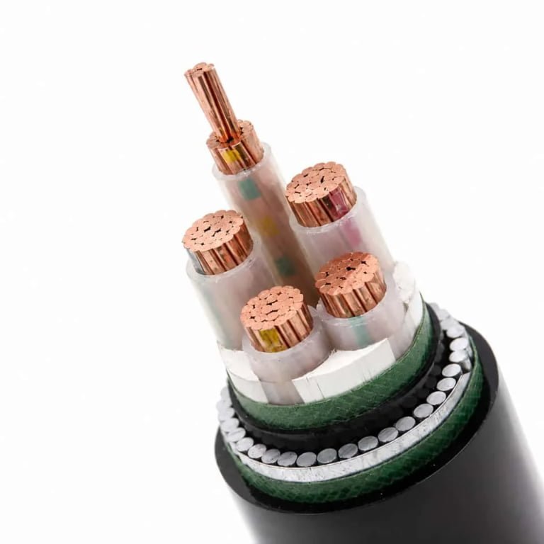
Armored cable gets specified for good reasons — mechanical protection, rodent resistance, the ability to run exposed through areas where flexible conduit would get damaged inside a week. But once it’s on the reel and the crew is pulling it, the weight, the stiffness, and the termination labor have a way of surfacing costs and complications that weren’t fully priced into the project. A single routing change through a tight cable tray can eat half a day of rework when your SWA simply won’t bend tight enough to fit. That’s not a design edge case; it happens regularly on retrofit jobs and congested industrial panels.
The primary limitation of armored cable is its reduced flexibility and larger minimum bend radius — typically 6–8 times the overall cable diameter for steel wire armored types — which complicates routing in confined spaces, increases installation labor by roughly 25–40% over unarmored equivalents, and adds 15–35% to per-meter cable weight, all of which drive up both installed cost and long-term handling difficulty.
What makes this worth a closer look is that the limitation isn’t just a one-time installation inconvenience. It ripples outward — into termination practices, cable tray sizing, structural load calculations, and even the skill level you need on-site the day the cable goes in. Get any of those wrong and you’re looking at damaged armor, stressed conductors, or failed glands that void your protection rating entirely.
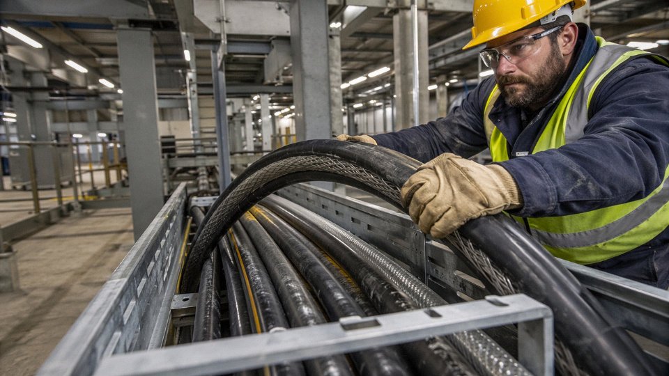
Mechanical Rigidity: Why Armor Construction Restricts Bending, Routing, and Field Flexibility
Steel wire armoring solves real problems — crush resistance, rodent protection, pulling tension across long runs. But the same construction that makes SWA cable tough in a straight trench makes it genuinely awkward the moment your routing requires a tight corner, a crowded junction box, or any application where the cable moves after installation.
Bending Radius: The Numbers That Catch Installers Off Guard
The minimum bending radius for steel wire armored cable is generally 6–8× the overall cable diameter, depending on voltage class and conductor cross-section. That multiplier sounds abstract until you’re standing in front of a 400 mm² SWA cable with a 78 mm overall diameter and realize your “comfortable” bend needs something north of 500 mm of clear radius. An unarmored XLPE cable of equivalent conductor size typically allows 4–6× — not a trivial difference when you’re working in a confined substation entry or a congested basement cable route.
Smaller conductors are less punishing but still stiffer than their unarmored equivalents. A 16 mm² SWA four-core LV cable might have an overall diameter around 20–22 mm, giving a minimum bend radius of roughly 130–175 mm. The equivalent unarmored flexible cable can comfortably manage 80–110 mm. That gap matters when you’re threading through a 150 mm conduit stub or making the entry bend into a wall-mounted distribution board.
Armor Type and Voltage Class Change the Equation
| Armor Type | LV (≤1 kV) Min. Bend Radius | MV (1–35 kV) Min. Bend Radius | HV (>35 kV) Min. Bend Radius |
|---|---|---|---|
| Steel Wire Armor (SWA) | 6× OD | 8× OD | 10–12× OD |
| Aluminum Wire Armor (AWA) | 6× OD | 7–8× OD | 9–10× OD |
| Steel Tape Armor (STA) | 8–10× OD | 10–12× OD | 12–15× OD |
OD = overall cable diameter. Actual figures depend on manufacturer construction, insulation material, and applicable standard (IEC 60502, BS 5467, etc.).
Steel tape armor is the stiffest of the three. The overlapping or butt-wound steel tapes form essentially a semi-rigid tube — and STA cables at medium and high voltage need substantially more bending radius than most field engineers budget for when laying out duct runs. AWA is meaningfully more flexible than SWA at equivalent cross-sections because aluminum wire has lower bending stiffness, which is worth specifying if your route has several direction changes.
Where Rigidity Actively Causes Problems
Crane cables, festoon systems, robotic arm wiring, any application with continuous flexing or torsional movement — armored cable is the wrong answer, full stop. The interlocked steel wires or tape layers are not designed to cycle through bending millions of times. In dynamic applications, the armor wires begin to work against each other, fatigue accelerates, and you eventually get fretting and wire fracture long before the conductor itself would fail. The fix is purpose-built flexible cable with appropriate mechanical protection for the environment, not standard SWA.
Steel wire armored cable is unsuitable for continuous-flex applications such as crane festoon systems or robotic arm cablesTrue
SWA construction uses rigid interlocked steel wires optimized for static mechanical protection, not cyclic bending. Repeated flexing causes armor wire fatigue, fretting, and eventual fracture — fundamentally different from the stranded or braided constructions used in dynamic-flex cable designs.
Routing in congested cable trays is its own frustration. A 35 mm² SWA cable might need 240–280 mm of bend radius to change direction in a tray, while a screened unarmored flexible of the same conductor size can negotiate the same tray corner in roughly half the space. When you’re filling a tray to capacity with multiple circuits, that geometry difference eats into fill rates and forces larger tray widths or additional support brackets — both cost and labor implications that procurement rarely models upfront.
The Bird-Caging Problem
Violate the minimum bending radius during installation and the armor wires don’t just stretch — they splay outward in a pattern the trade correctly calls bird-caging. The wires lose their wound geometry, the inner sheath can be punctured or distorted, and the cable’s overall diameter increases locally. Beyond the obvious mechanical damage, bird-caged armor no longer provides continuous electrical bonding along its length, which compromises fault current return paths in earthed systems and can create dangerous touch potentials at the deformed section. Tape armor fails differently — the tape laps open or the butt joints separate — but the result is the same: the armor is no longer structurally or electrically continuous.
In practice, bird-caging happens most often at entry bends into panels and at the first support point after a cable enters a trench or duct. The cable is still relatively rigid from being on the drum, the crew is working in a tight space, and the bend gets pulled too tight before the cable has been properly laid out and slacked.
Matching Cable Construction to Actual Site Geometry
Jinda’s product selection process for international projects starts by mapping routing geometry before specifying armor type — specifically flagging routes with cumulative direction changes greater than 180° over short runs, entry bends into switchgear, and any section of cable that will see movement post-installation. For those segments, the choice might shift to AWA instead of SWA, or to an unarmored design with mechanical protection provided by conduit or duct, rather than forcing an SWA cable through a geometry it will resist at installation and potentially damage over time. The weight penalty of steel wire armor — roughly 15–35% heavier per meter than the unarmored equivalent, depending on cross-section and voltage rating — also compounds the routing difficulty, since heavier cables require more frequent support and generate higher sidewall bearing forces on bends in duct systems.
Elevated Installation Cost and Labor Complexity Compared to Unarmored Cable Systems
The cable itself is rarely the biggest line item on an armored cable project. That surprises a lot of procurement managers the first time they run a full installed-cost comparison. The armor construction that makes SWA cable so robust underground or in industrial environments also demands a specific set of accessories, tools, and skills at every single termination — and those requirements stack up fast.
Breaking Down the True Cost Components
Start with the glands. A standard cable gland for unarmored cable might cost a few dollars in most markets. A properly specified SWA brass gland with shroud, locknut, and earth tag — the full assembly — runs anywhere from two to five times that price per termination, depending on cable diameter, IP rating required, and whether you’re specifying nickel-plated brass for marine or corrosive environments. On a modest industrial project with 80 or 100 termination points, that delta is already meaningful before you’ve picked up a tool.
Then there’s the cutting and preparation work. Stripping SWA cable correctly requires either a quality rotary armour cutter (a decent Greenlee or equivalent runs $150–$300, more for larger sizes) or, in the field, a hacksaw and a level of care that most electricians don’t consistently apply under schedule pressure. Nicked inner sheaths, uneven armor cuts, wire ends left protruding — these are not hypothetical. They’re routine inspection findings on projects where the foreman didn’t enforce termination procedure.
Earth continuity bonding through the armor is non-negotiable for fault protection, and it adds another step that unarmored cable simply doesn’t have. The armor wires need to be gathered, checked for continuity, and secured properly through the gland’s earth tag and then bonded back to the enclosure earth bar. Skip this or do it poorly and you’ve created a high-impedance earth path. In a fault condition, that translates directly to delayed protection operation — potentially long enough to cause equipment damage or, in a worst case, a fire.
Gland Selection: Where Mistakes Get Expensive
The gland type matters more than most site teams appreciate. Type A glands clamp only the outer sheath — they provide no mechanical retention of the armor itself, which means they’re unsuitable for direct burial or anywhere mechanical pull-out is a real risk. Type B glands clamp the armor; type C clamp both armor and outer sheath for environments with torsional stress. CW (cable wire) glands are the choice for steel wire armored cable specifically, providing armor clamping with earth continuity through the gland body.
Using a Type A gland on SWA cable in a below-grade installation can void the cable manufacturer's warranty and creates a latent mechanical failure risk at the entry pointTrue
Type A glands do not grip the armor layer, leaving the armor termination unsupported against axial pull or soil movement. Most SWA cable manufacturers and IEC installation standards require armor-clamping glands for buried or mechanically stressed installations.
Wrong gland, wrong result. A facility maintenance team that inherits an installation where someone used standard unarmored glands on SWA cable will often discover the problem only when armor corrosion shows up at the entry point years later, or when a cable pulls back slightly under thermal cycling and the inner conductors take the mechanical stress.
The Time Cost Nobody Budgets Properly
A competent electrician terminating unarmored XLPE tray cable into a standard enclosure — strip, identify cores, land on terminals — might take 20 to 30 minutes per termination at a straightforward 4-core, 6 mm² size. The equivalent SWA termination, done correctly with proper gland assembly, armor preparation, bonding, shroud fitting, and continuity check, typically runs 45 to 65 minutes. That’s not inefficiency; that’s just what the process requires. Scaled across a large panel with 40 incoming cables, you’re looking at a full extra day of electrician time on that enclosure alone.
This feeds directly into the 25–40% labor cost premium that armored cable installations carry over unarmored equivalents — a range that depends on local labor rates, project scale, and how much of the work is in confined spaces or elevated positions where the cable weight (itself 15–35% heavier per meter than unarmored equivalents at the same cross-section) creates additional handling burden.
Installed Cost Comparison Across Project Scales
| Project Scale | SWA Installed Cost Index | Unarmored XLPE Tray Cable Index | Primary Cost Driver for Premium |
|---|---|---|---|
| Small (under 50 terminations) | 1.00 | 0.58–0.65 | Gland accessories as % of total; setup cost amortized over few points |
| Medium (50–300 terminations) | 1.00 | 0.65–0.72 | Labor differential dominates; accessory cost per point stabilizes |
| Large (300+ terminations) | 1.00 | 0.70–0.78 | Bulk gland pricing narrows gap slightly; skilled labor sourcing becomes constraint |
Index normalized to SWA = 1.00 at each scale. Actual figures depend on local labor rates, cable voltage class, and site access conditions.
The Skilled Labor Problem in Remote Markets
This is the dimension that rarely appears in cost models but consistently appears in post-project reviews. In established industrial markets — western Europe, North America, Australia — SWA termination is a standard electrician competency. In many of the developing-market regions where infrastructure projects drive cable demand, it isn’t. A project in a remote location might have locally available general electricians who have never terminated SWA cable, which means either importing supervision, budgeting for rework, or accepting termination quality risk.
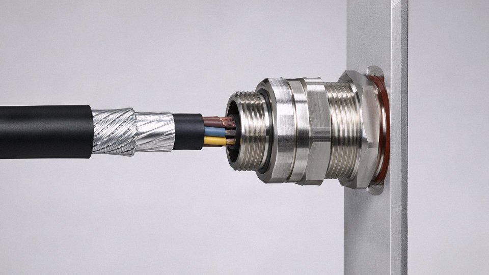
For procurement managers sourcing SWA cable for projects in those markets, the right question to ask before finalizing the specification isn’t just “what’s the cable price?” It’s “do we have the termination capability on site, and if not, what does closing that gap actually cost?”
Weight and Handling Penalties That Affect Transport, Drum Logistics, and Structural Loading
Steel wire armoring adds meaningful mass — and that mass ripples through procurement, freight, site logistics, and structural design in ways that often catch project teams off guard, usually when it’s too late to do much about it.
To put real numbers to the problem: a 4 mm² three-core SWA cable typically weighs somewhere in the range of 0.28–0.36 kg/m, against roughly 0.22–0.28 kg/m for an unarmored equivalent. Scale up to 95 mm² three-core, and you’re looking at around 2.1–2.6 kg/m armored versus 1.7–2.1 kg/m unarmored. At 240 mm² three-core, the gap widens further — armored cable commonly runs 4.8–5.8 kg/m depending on voltage rating and conductor material, compared to 3.8–4.6 kg/m without armor. The 15–35% mass penalty stated in cable datasheets isn’t evenly distributed across sizes; larger conductors and higher-voltage constructions with thicker insulation packages tend to sit toward the lower end of that range proportionally, because the armor wire diameter doesn’t scale linearly with conductor size. Smaller cables see the bigger relative penalty.
Drum Lengths, Joint Count, and Freight Economics
Standard export drums for heavy SWA cable are limited by gross weight — most road freight and general cargo shipping works around drum weights in the 2–3.5 tonne range as a practical handling ceiling, though this depends on the logistics chain and destination country’s road weight regulations. When a cable is heavier per meter, the maximum drum length drops to stay within that weight ceiling. A 240 mm² SWA cable that might give you 350–400 m per drum under normal constraints might only yield 250–300 m once you factor in drum tare weight and freight class limits. On a long cable run — say, 1,500 m across an industrial site or a marine jetty — that difference can mean one additional joint. Joints cost money, introduce potential failure points, and on some project specifications (offshore pipelines, certain mining classifications) are prohibited or heavily restricted. The weight-per-drum issue genuinely affects system design, not just logistics paperwork.
Cable Tray and Structural Load Calculations
Structural engineers calculating cable tray and ladder rack support systems typically work from fill weight — the combined dead load of cables per linear meter of tray. Substituting SWA cable into a tray that was originally sized for unarmored cables can push the load per support span outside the original design envelope. In practice, this can mean reducing support spacing from, say, 1.5 m down to 1.2 m, or upgrading from standard-duty to heavy-duty tray sections. Neither is catastrophic, but both add cost and, more annoyingly, require structural drawings to be revised late in the design cycle. I’ve seen this exact issue cause schedule slippage on electrical installation packages where the structural steelwork was already fabricated before the cable schedule was finalized. Worth checking early.
Offshore, Elevated, and Weight-Critical Installations
On offshore platforms, suspension bridges, and high-rise buildings, every kilogram of cable adds to permanent structural load, and structural steel costs money per tonne in a way that’s brutally direct. On a large platform topsides with several kilometers of HV and LV SWA runs, the cumulative weight difference versus a lighter alternative can run into several tonnes — enough to matter for topside weight budgets.
Armored cable weight is a significant factor in offshore platform topsides weight budgets for large electrical installations.True
Offshore platform design involves strict topsides weight limits; cumulative cable mass across HV and LV systems contributes meaningfully to structural load, and this is standard practice in offshore electrical engineering design reviews.
Site Handling and Drum Logistics
Heavier drums require forklifts or cable drum trailers rather than manual handling. On congested construction sites — urban substation builds, plant turnarounds, basement electrical rooms — getting a 2.5-tonne drum into position can be a genuine logistical exercise. The equipment rental cost is real; so is the schedule risk if access is tight and a drum move takes two hours instead of twenty minutes.
Jinda’s logistics and commercial teams factor drum gross weight, shipping volume, and port-of-discharge handling requirements directly into international project quotations. For bulk buyers pricing a cable package across multiple voltage levels and cross-sections, this matters: the freight cost difference between armored and unarmored equivalents over a large order can shift landed unit costs by more than the cable list price differential suggests. Getting that calculation wrong at tender stage is an unpleasant surprise at invoice stage.
Corrosion Vulnerability of Steel Armor in Chemically Aggressive and Marine Environments
Steel wire armor protects against mechanical damage. That much is obvious. What catches engineers out is that the armor itself can become the failure point, quietly degrading over years until a fault or a dig-up reveals wire strands that crumble like rust flakes.
The Electrochemical Mechanism Behind Armor Degradation
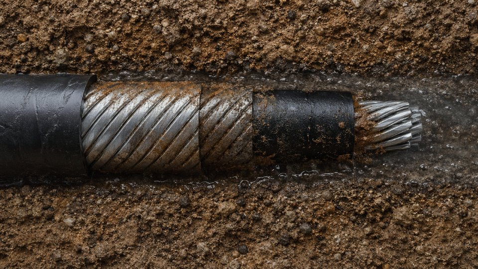
Galvanized steel wire armor corrodes through straightforward electrochemical reactions, but the rate and severity depend heavily on what surrounds the cable. In acidic soils — pH below roughly 5, common near peat bogs, colliery spoil heaps, and some reclaimed industrial land — zinc galvanizing is consumed faster than most installation engineers budget for, sometimes within 8–15 years rather than the 30-plus years assumed at design. Once the zinc layer is gone, the bare steel underneath corrodes aggressively.
Coastal soils are a separate problem. High chloride concentrations accelerate the breakdown of the passive oxide layer on steel, and the combination of moisture, salt, and oxygen creates near-ideal conditions for pitting corrosion. The pitting is insidious because it’s localized — a cable can look intact along most of its run while a 200 mm section near a tidal boundary has lost 60–80% of wire cross-section.
Stray DC currents add another layer of risk that’s easy to miss during design. In areas near DC traction systems, cathodic protection networks, or electrolytic industrial processes, stray current leaves the cable armor at anodic discharge points, accelerating metal loss at those spots enormously. A cable buried near a DC rail line without proper stray current mitigation can show severe armor corrosion at discharge points within 3–5 years — a timeline that catches maintenance teams completely off-guard.
What Armor Corrosion Actually Does to the Cable System
The mechanical protection degrades first, obviously. But the less-discussed consequence is the reduction in earth fault current carrying capacity. Steel wire armor is frequently used as the circuit protective conductor in UK-style SWA installations. As wire cross-section diminishes, so does its ability to carry fault current long enough for protection devices to operate correctly. An armor that’s lost significant cross-section may fail thermally during a ground fault before the breaker clears — leaving damaged insulation, potential arc damage, and a very unpleasant post-incident investigation.
Eventually, corrosion perforates the bedding layer and allows moisture tracking into the insulation system. XLPE and EPR insulation tolerate some moisture, but sustained ingress at elevated operating temperatures accelerates treeing, and at that point you’re looking at full cable replacement rather than a repair.
Corroded steel wire armor can fail to carry design earth fault current even when the cable insulation appears externally intact.True
Armor corrosion reduces the metallic cross-section of the CPC path; if armor wires lose significant area, the impedance rises and thermal withstand during fault duration may be inadequate for protective device coordination, independent of insulation condition.
Armor Material Selection: Where the Real Engineering Decision Sits
Galvanized steel wire is the default, and it’s fine for many applications. But it’s been specified on autopilot in environments where it simply isn’t appropriate.
Aluminum wire armor (AWA) offers meaningfully better corrosion resistance in most soil types and is the correct choice for aluminum-sheathed cables from a galvanic compatibility standpoint — pairing steel armor with an aluminum sheath creates a galvanic cell that accelerates corrosion of the aluminum sheath at contact points. For single-core AC power cables, AWA also avoids the induced circulating current losses you get with a magnetic steel armor, which is a separate efficiency argument entirely.
Stainless steel armor gives the best corrosion performance but costs roughly 3–6× more than standard galvanized wire depending on grade and market conditions, and it’s usually reserved for chemical plant trenches with known aggressive contamination or offshore topside applications where the economics justify it.
Plastic-bedded construction — where an extruded inner bedding separates armor from sheath — slows moisture contact and reduces galvanic exposure somewhat, but it’s a mitigation, not a solution. Bedding alone won’t save galvanized armor in genuinely hostile ground chemistry.
Failure Modes in High-Risk Installation Environments
Direct-buried SWA in coastal reclamation areas consistently shows the fastest degradation, in my observation. The problem is the ground itself: reclaimed land is often heterogeneous, with pockets of marine sediment, fill material, and variable drainage, which creates differential aeration cells along the cable route. These cells set up corrosion at boundaries between well-oxygenated and oxygen-depleted zones — exactly where you least expect it and rarely inspect.
Wetland installations share similar risk. Anaerobic sulfate-reducing bacteria in waterlogged soils produce hydrogen sulfide, which attacks steel armor directly and also increases ground acidity locally. This is one environment where specifying standard SWA and relying on galvanizing is genuinely optimistic.
Chemical plant sites with soil contamination — chlorinated solvents, acid spills, process effluent — require site-specific soil analysis before cable selection. Broad assumptions about “industrial soil” don’t hold.
Armor Material Suitability Matrix
| Environment | Galvanized SWA | Aluminum Wire Armor (AWA) | Stainless Steel Armor | Notes |
|---|---|---|---|---|
| Indoor dry | Suitable | Suitable | Over-specified | Standard SWA is practical here |
| Neutral soil, buried | Suitable | Suitable | Over-specified | Verify soil pH before assuming “neutral” |
| Acidic soil (pH < 5) | Conditional | Suitable | Suitable | SWA requires corrosion protection wrap |
| Marine / high chloride | Not recommended | Conditional | Suitable | AWA still needs bedding attention |
| Coastal reclamation | Not recommended | Conditional | Suitable | Heterogeneous soil increases risk |
| Wetland / anaerobic soil | Not recommended | Conditional | Suitable | Bacterial sulfide attack is the key risk |
| Chemical plant (contaminated soil) | Not recommended | Conditional | Suitable | Site soil analysis mandatory |
| DC stray current zone | Conditional | Conditional | Conditional | Material choice secondary to cathodic protection design |
“Conditional” here means it can work with additional protective measures — corrosion-resistant bedding, anti-corrosion tape wraps, cathodic protection, or increased inspection frequency. It does not mean suitable without modification.
The practical takeaway: armor material selection belongs in the design stage, not the procurement stage. By the time a project buyer is placing a cable order, the window for switching from SWA to AWA or specifying stainless armor without cost and schedule impact is usually already closing. Soil survey data should inform the cable specification, not get filed away after the civil works are scoped.
Electromagnetic and Earthing Complications Introduced by Metallic Armor on Single-Core Cables
Steel wire armor works well on multicore cables. On single-core AC power cables, it creates a set of electrical problems serious enough that most international standards effectively steer engineers away from it — yet procurement teams still specify it, usually because they’re matching a familiar line item on a legacy bill of materials without checking the conductor configuration.
Why Steel Armor and Single-Core AC Are a Bad Combination
The physics is straightforward once you think about it. A single-core cable carrying AC current produces an alternating magnetic field around the conductor. In a multicore cable, the fields from each conductor largely cancel. In a single-core cable, there’s no cancellation — the armor sits in a strong, pulsating magnetic field. Steel wire armor has relatively high magnetic permeability, which means it couples with that field efficiently, inducing a voltage along the armor sheath. If the armor is bonded at both ends (the natural instinct for fault protection), that induced voltage drives a circulating current around the loop formed by the armor and the earth return path.
That circulating current generates heat. The cable runs hotter than its rated temperature predicts, and the thermal derating required to compensate is not trivial.
The Derating Problem in Practice
Single-core SWA cables on AC systems typically lose somewhere in the range of 10–20% of their rated current-carrying capacity compared to an equivalent cable with aluminum wire armor (AWA). The exact figure depends on conductor cross-section, installation grouping, soil or ambient temperature, and how the armor is bonded — but 15% is a realistic working assumption for a medium-voltage circuit in the 95–240 mm² range installed in flat formation.
That derating has real consequences. A 185 mm² single-core SWA cable that looks adequate on paper may force you to upsize to 240 mm² to carry the same load safely. You’ve now bought a heavier, more expensive cable specifically to compensate for a limitation introduced by the wrong armor material.
Single-core steel wire armored cables on AC systems incur significant circulating current losses that reduce current-carrying capacity compared to aluminum wire armored equivalents.True
This is consistent with IEC 60502-1 guidance and well-established electromagnetic principles; steel's ferromagnetic properties cause higher induced losses in single-core AC configurations than non-magnetic aluminum armor.
AWA as the Correct Specification — and Why It Gets Missed
Aluminum wire armor is non-magnetic. It still provides mechanical protection and a fault current return path, but it doesn’t couple with the AC magnetic field in the same way. The circulating current losses are substantially lower, and derating factors are far more favorable. For single-core MV and HV cables, AWA is the technically correct choice.
The procurement mistake happens because SWA is cheaper per meter and is the default on many distributor price lists. An engineer specifying a 6.6 kV or 11 kV single-core circuit sometimes copies the armor type from a previous multicore project without adjusting for the single-core case. The cable arrives, gets installed, and the thermal problem shows up gradually — slightly elevated operating temperatures, faster insulation aging, unexplained load limitations. Rarely a dramatic failure; usually a slow degradation that’s difficult to trace back to the original specification.
Earthing Strategy: One End, Both Ends, or Cross-Bonded
Even with the correct armor material, single-core armored cables introduce an earthing decision that multicore installations don’t face in the same way.
Bonding the armor at both ends creates a closed loop. For a short run — say, under 50 m in a substation — this is generally acceptable because the induced voltage is low and the circulating current remains manageable. For longer runs, the circulating current in a both-ends-bonded system can reach levels that noticeably affect ampacity and generate measurable additional losses.
Single-point bonding (earthing the armor at one end only, with a voltage-limiting device at the unearthed end) eliminates circulating currents but introduces a standing induced voltage on the unearthed end. BS 7671 and IEC 60502-2 both address this; the permitted standing voltage on an unearthed armor end is limited, typically to values in the range of 25–65 V depending on the standard and installation context. Exceeding that threshold means single-point bonding alone isn’t sufficient.
For long HV cable circuits — transmission feeders, inter-substation links, offshore wind export cables — cross-bonding is the standard engineering solution. The cable route is divided into three roughly equal sections, and the armor sheaths are transposed at each joint bay so that the induced voltages in consecutive sections cancel. It works well, but it adds joint bays, specialized link boxes, and surge voltage limiters to the installation. That’s real additional cost and complexity: link boxes for a cross-bonded HV circuit typically add somewhere between 8–15% to the civil and accessories cost of the cable route, depending on route length and number of circuits.
Standards Guidance and Specification Support
IEC 60502-2 covers power cables rated 6 kV through 30 kV and includes explicit guidance on armor material selection for single-core configurations. BS 7671 (the IET Wiring Regulations) addresses bonding and earthing arrangements for armored cables in Part 5, with specific attention to induced voltages on single-core installations. Neither document prohibits SWA on single-core cables outright, but the derating requirements in IEC 60287 (the current-carrying capacity calculation standard) make the performance penalty of ferromagnetic armor on single-core AC circuits numerically clear once you run the numbers.
In practice, customers sourcing single-core MV cables sometimes arrive with a specification that simply says “SWA” without recognizing the issue. Jinda’s technical support team routinely reviews single-core cable specifications before production and flags cases where AWA would be the more appropriate construction — particularly for voltage classes above 3.6/6 kV where the induced voltage effect is more pronounced. Getting the armor material right at the design stage costs nothing. Discovering it after installation is a different conversation entirely.
Repair, Jointing, and Modification Challenges That Increase Lifecycle Maintenance Cost
Armor protects cable during installation and service life. That same armor becomes a serious obstacle the moment something goes wrong underground or inside a congested cable tray — and in direct-buried runs, “something going wrong” is not rare. Mechanical damage from excavation by third parties, insulation degradation from water ingress at a poorly sealed gland, or a single fault in a long buried run all demand a repair process that is substantially more involved than anything you’d face with an unarmored equivalent.
What an Armored Cable Repair Actually Looks Like on Site
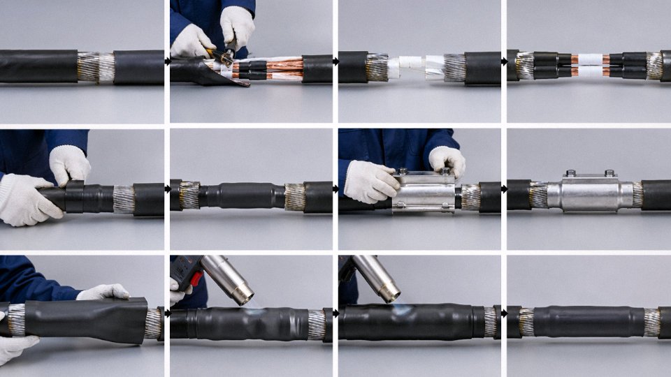
Walk through a typical fault repair on a direct-buried SWA run and the steps accumulate fast. First, excavation — which on a road crossing or beneath a concrete slab means groundworks costs before any cable work begins. Once exposed, the damaged section needs to be isolated, the outer sheath stripped back far enough to work cleanly (usually 300–500 mm either side of the fault, depending on damage extent), and the steel wire armor cut back using armor cutters or an angle grinder with a cutting disc. Cutting the armor without nicking the bedding or inner sheath underneath takes practice; I’ve seen inexperienced jointers cause secondary insulation damage at this stage, which extends the repair. Then comes insulation repair or, more commonly on MV cables, full joint installation using a heat-shrink or cold-shrink joint kit. The kit has to be rated for the armor type — SWA and STA (steel tape armored) joints are not interchangeable. After jointing, re-armoring or an approved armored joint kit with integral armor continuity bridging gets installed, the whole assembly is protected and reinstated, and the earthing continuity across the joint needs to be verified.
Compare that to repairing a damaged unarmored cable: strip back sheath, splice conductors, apply insulation tape or a simple heat-shrink sleeve, done. Time difference is real. A competent jointer on an armored joint kit, working in reasonable ground conditions, will typically spend 4–8 hours on a single straight-through joint. The equivalent unarmored repair can be done in under 2 hours. Material costs follow the same ratio — armored joint kits for medium voltage applications run roughly 3–5 times the material cost of unarmored equivalents, and that’s before the groundworks, re-excavation, and reinstatement.
Armored cable straight-through joints cost approximately 3–5 times more in combined labor and materials than equivalent unarmored cable repairs under comparable field conditions.True
This reflects the additional steps of armor cutting, armor continuity bridging, rated joint kit requirements, extended strip-back lengths, and longer jointing time — all well documented in utility and industrial maintenance cost benchmarks.
Fault Location Is Harder Than It Sounds
Steel wire armor interferes with acoustic fault location methods and can complicate TDR (time domain reflectometry) readings. The metallic armor creates a secondary conductive layer that masks precise impedance discontinuities, meaning TDR results often need to be interpreted alongside sheath fault testing to triangulate the fault position to within an acceptable window — sometimes still leaving a 5–15 m excavation zone rather than a clean pinpoint. On congested cable corridors where multiple armored circuits run parallel, this problem gets worse.
Modifications Are Rarely Simple
Re-routing an installed armored run around a new pipe penetration or structural column is usually not feasible without replacing the affected section entirely. The rigid construction won’t accommodate the tight redirections that flexible unarmored cable handles without issue. Adding a branch feed requires a T-joint — itself a specialist job — rather than simply looping in a flexible spur.
Minimizing Joints Through Drum Length Planning
This is one area where procurement decisions made before installation directly reduce lifecycle maintenance exposure. Jinda supplies armored cable on project-specific drum lengths calibrated to the actual route measurements provided by the customer — eliminating unnecessary field joints that would otherwise become future maintenance points. For international projects where qualified jointers are expensive or scarce, reducing the total joint count through accurate pre-project length planning is worth real money over a 20–30 year cable life.
Selecting the Right Armored Cable Specification to Mitigate These Limitations: A Practical Decision Framework
Every limitation covered in the sections above — rigidity, weight, corrosion, induced currents, repair cost — is manageable when the specification decision is made deliberately. Most field problems I’ve seen come from the same root cause: someone defaulted to SWA because “it’s a buried cable” without asking whether the environment actually demanded steel armor, or whether the routing called for something more flexible. The framework below is meant to force that conversation before the purchase order goes out.
Start With Installation Environment, Not Armor Type
The decision tree should open at the installation environment because that single variable eliminates several armor types immediately.
Direct burial in normal soil with mechanical risk from excavation equipment is the classic SWA or STA (steel tape armored) use case. Burial in waterlogged ground or coastal fill changes the answer — galvanized steel armor in persistently wet chloride-rich soil will begin oxidizing within a few years depending on coating quality and soil pH, which pushes the specification toward aluminum wire armor (AWA) or a double-sheathed construction. Cable trays in a dry indoor environment often don’t need armor at all; a correctly sized HDPE duct or galvanized tray with a heavy-duty PVC-sheathed unarmored cable can provide adequate mechanical protection at meaningfully lower installed cost and without the bending radius penalty.
Exposed vertical drops, mine shafts, and offshore risers are where SWA genuinely earns its place — the tensile load handling is real and relevant.
Once environment is established, layer in mechanical risk (probability of post-installation excavation damage, vehicular traffic above, presence of rodents), then chemical exposure (hydrocarbon, acidic, marine salt), then single-core versus multicore, then voltage class. Single-core cables above roughly 1 kV carrying AC current need AWA rather than SWA for the circulating current reasons already discussed — specifying SWA on a single-core MV feeder is a code-compliance issue in many jurisdictions, not just an efficiency concern.
Specification Checklist Before You Issue a Datasheet
Armor material: SWA for standard multicore LV/MV in dry or moderately wet environments; AWA for single-core AC circuits or aluminum-sheathed systems; STA where the priority is crush resistance over tensile strength. Armor wire diameter matters more than most procurement teams realize — thicker wires raise the bending radius and add weight, but thinner wires reduce tensile and crush performance. This is where a non-standard wire diameter becomes worth discussing with the manufacturer rather than accepting the catalog default.
Bedding material beneath the armor should be compatible with conductor insulation temperature rating. A PE inner sheath under armor on a 90°C-rated cable, combined with a PVC outer, creates a thermal mismatch that shortens service life in high-load cycling applications.
Outer sheath compound: PVC is adequate for most LV installations but emits halogen gases in fire. LSZH (low-smoke zero-halogen) is specified in tunnels, public buildings, and offshore installations per IEC 60332 and similar. HDPE outer sheaths offer better chemical resistance and are worth the modest cost premium in chemical plants or direct burial in aggressive soils. Gland selection must match sheath and armor type — a brass SWA gland on an AWA cable creates a galvanic corrosion pair at the termination. It’s a surprisingly common mistake.
When Armor Isn’t the Answer
Concrete encasement, HDPE ducting, or proprietary cable protection covers can replace armor entirely in many buried or surface-routed installations, removing the weight penalty, the bending constraints, and the termination cost in one decision. The duct approach also enables future cable replacement without excavation — a lifecycle cost argument that’s hard to ignore on long runs.
HDPE duct with unarmored cable can replace SWA in many direct-burial applications, reducing total installed cost and enabling future cable replacement without re-excavation.True
Where mechanical risk comes from post-installation disturbance rather than installation handling, a Schedule 40 or SDR11 HDPE duct provides equivalent physical protection at lower cable unit cost, with added flexibility for future upgrades. This approach is documented in IEC and NEC installation practice guidance.
Standards as a Baseline, Not a Ceiling
IEC 60502-1 (LV) and IEC 60502-2 (MV) define minimum armor construction requirements — wire diameter tolerances, tensile test loads, coating specifications. BS 5467 and BS 6724 cover SWA and LSZH-sheathed armored cables respectively in the British standards framework. Compliance with these is the floor. For genuinely aggressive environments — offshore, petrochemical, high-cycling industrial — the right approach is to treat the standard as a starting point and specify upward from there: heavier wall bedding, dual sheath, or non-standard armor wire to hit a specific crush load or bend radius requirement.
Jinda’s engineering team works with project specifications that sit outside standard catalog constructions — hybrid bedding systems combining PE and EPR, armor wire diameters specified to hit a project-specific bending radius target, or outer sheaths combining LSZH compound with a mechanical abrasion layer. These aren’t exotic requests; they’re routine for any manufacturer with real process flexibility.
The underlying rule is simple. Armor is an engineering compromise — it adds protection and adds cost, weight, rigidity, and complexity in exchange. Those trade-offs only become problems when the cable is specified without a clear-eyed look at what the installation actually demands.
Frequently Asked Questions About Armored Cable Limitations
What is one limitation when using armored cable?
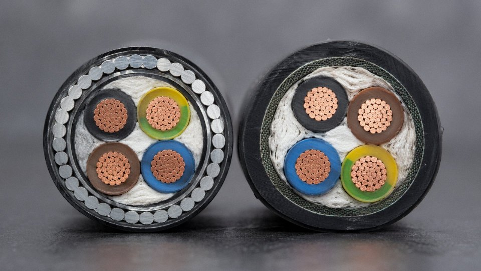
The single most consequential limitation of armored cable is its mechanical rigidity combined with the installation complexity that rigidity creates. Steel wire armored cable has a minimum bending radius of roughly 6–8 times the overall cable diameter — significantly tighter routing is simply not possible without risking armor wire distortion or insulation damage. That stiffness cascades into higher labor costs (typically 25–40% above unarmored equivalents), specialist termination tools, careful gland selection, and longer installation schedules. In short: armored cable is a deliberate trade of flexibility and ease of handling for mechanical protection. On many projects that trade is absolutely worth making. The limitation is not that the armor exists — it’s that specifying it without accounting for these downstream installation realities consistently blows budgets and timelines.
Can armored cable be used in continuous-flex applications?
Standard SWA and steel tape armored (STA) cables are not rated for continuous flexing. Full stop. The individual armor wires or tapes are designed for static or semi-static installation; repeated bending cycles work-harden the steel, promote fatigue cracking in the armor layer, and can eventually damage the insulation beneath. For continuous-flex duty — robot cable tracks (e.g., igus-style energy chains), crane trailing cables, festoon systems — you need purpose-built constructions: braided armor over a flexible stranded core, or fine-wire screened flexible cables where appropriate. The stranding geometry, conductor flexibility class, and sheath compound all matter. Specifying a standard SWA cable on a moving application because “it’s tougher” is a common procurement mistake that typically results in premature failure within 12–24 months.
Does armor on a single-core cable cause power loss?
Yes, with steel armor it can — and the effect is worth quantifying before you dismiss it. Steel is ferromagnetic, so when a single-core AC cable carries current, the magnetic field induces circulating currents in a continuous steel armor layer. Depending on load current and system voltage, this can add meaningfully to losses and cause localized heating. The practical solution is aluminum wire armor (AWA). Aluminum is non-ferromagnetic, so induced losses are negligible. For single-core MV or LV cables carrying substantial AC current, AWA is not a premium option — it’s the correct specification. Using SWA on single-core AC power cables to save a small upfront cost routinely creates efficiency and thermal problems that cost more to manage over the cable’s life.
Aluminum wire armor (AWA) eliminates the induced current losses that occur with steel wire armor on single-core AC cablesTrue
Steel armor is ferromagnetic and creates a continuous magnetic path around a single-core conductor, inducing circulating currents under AC operation. Aluminum is non-ferromagnetic, which breaks this mechanism and eliminates the associated losses.
How long does armored cable last underground?
Realistically, 25–40 years in direct burial — but that range depends heavily on several variables. Soil pH below about 5.5 or above 9 accelerates corrosion of steel armor noticeably. High soil resistivity and seasonal moisture fluctuations matter too. Installation quality is arguably the biggest factor: cable dragged over sharp backfill stones, bent beyond minimum radius during pulling, or buried without adequate bedding sand will fail well before the 25-year floor. PVC outer sheaths become brittle in soils with certain hydrocarbon contamination. A well-specified cable with HDPE sheathing, installed correctly in neutral-pH soil with proper bedding, can realistically reach or exceed the upper end of that range.
Is armored cable waterproof?
Armor alone is not a watertight barrier. Standard SWA or AWA construction with a PVC or HDPE outer sheath provides mechanical protection and reasonable resistance to incidental water contact, but it will not stop longitudinal water migration if the sheath is breached — water tracks along the interstices between armor wires over surprisingly long distances. For submarine applications, flood-prone ducts, or any installation where a sheath nick could expose the cable to sustained hydrostatic pressure, you need additional protection: longitudinal water-blocking tapes or powder under the sheath, or in demanding cases, a lead alloy sheath beneath the armor. Specifying “armored” and assuming “waterproof” is a mistake that shows up most painfully during post-fault investigation.
What is the difference between SWA and AWA cable, and which has fewer limitations?
| Parameter | SWA (Steel Wire Armor) | AWA (Aluminum Wire Armor) |
|---|---|---|
| Weight penalty | Higher — steel density adds 25–35% to cable weight | Lower — aluminum density roughly one-third of steel |
| Corrosion resistance | Moderate; needs PVC/HDPE sheath in aggressive environments | Better in most soil/marine conditions |
| Single-core AC suitability | Poor — induced losses significant | Preferred — non-ferromagnetic, low induced loss |
| Multi-core suitability | Excellent standard choice | Acceptable; slightly less mechanical crush resistance |
| Relative cost | Generally lower material cost | Slightly higher per meter, offset by weight/logistics savings |
Neither type is universally superior. SWA remains the default for multi-core power cables in standard industrial environments. AWA is the correct call for single-core AC power cables and for installations where weight or corrosion is the binding constraint.
How do I prevent armor corrosion in a coastal or chemically aggressive installation?
Start with material selection: specify AWA rather than SWA wherever soil chloride levels are elevated or the installation is within roughly 1–2 km of a marine environment — the exact threshold depends on local surveys, but coastal environments are unforgiving to bare steel over decades. Require an HDPE outer sheath rather than PVC; HDPE has meaningfully better chemical and moisture resistance. Before direct burial, test soil pH and resistivity — this takes a day and costs almost nothing compared to premature cable replacement. In particularly aggressive soils or where stray DC currents are present (near DC traction systems, for instance), cathodic protection deserves serious consideration for critical circuits. At termination points, use appropriate compound-filled glands and seal sheath ends properly; exposed armor cut-ends left open to atmosphere are a common corrosion initiation point that maintenance teams often overlook until it’s too late.