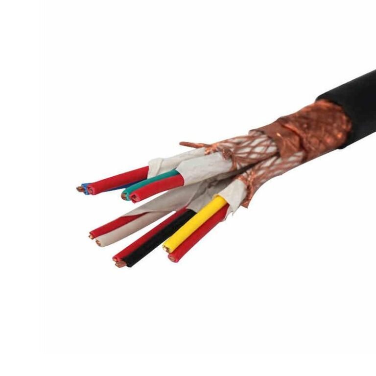
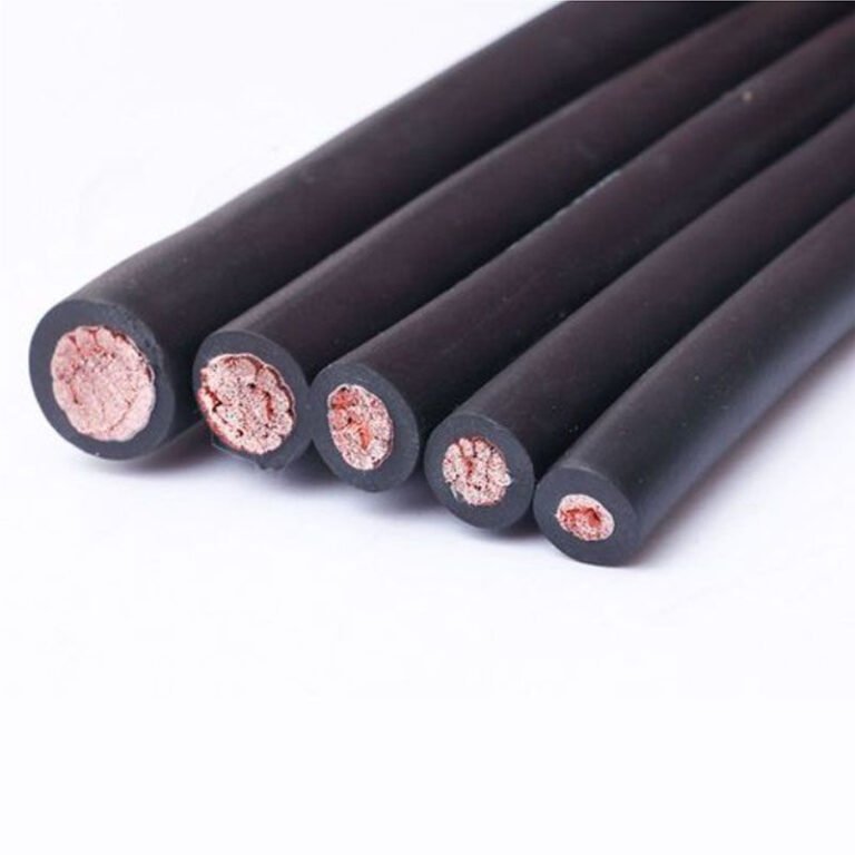
Specify the wrong wire type on a panel drawing, or let a procurement team substitute freely between live, neutral, and ground conductors without understanding what each one actually does, and you get problems that range from nuisance tripping all the way to arc flash events and failed inspections. The financial hit is rarely just the rewire — it’s the delay, the certification re-test, sometimes a scrapped switchgear assembly that took six weeks to build.
The three types of wires are the live (hot) wire, the neutral wire, and the ground (earth) wire. The live wire carries voltage — typically 120–240 V AC in residential systems — and delivers current to the load. The neutral wire returns current to the source at near-zero potential. The ground wire normally carries no current at all; it only conducts during a fault, providing a low-resistance path that trips the breaker before someone gets hurt.
What makes this more than a wiring-101 recap is what happens when you treat these three as interchangeable — or when you understand them well enough to make smarter decisions about conductor material, sizing, insulation color coding, and fault tolerance across different installation environments. Copper’s resistivity of roughly 1.68 × 10⁻⁸ Ω·m at 20°C versus aluminum’s 2.82 × 10⁻⁸ Ω·m means the choice of conductor affects every one of these three wire roles differently, and not always in the way a spec sheet suggests.
Live Wire (Hot Wire): Voltage Carrier, Color Codes, and Conductor Specifications Across Major Markets
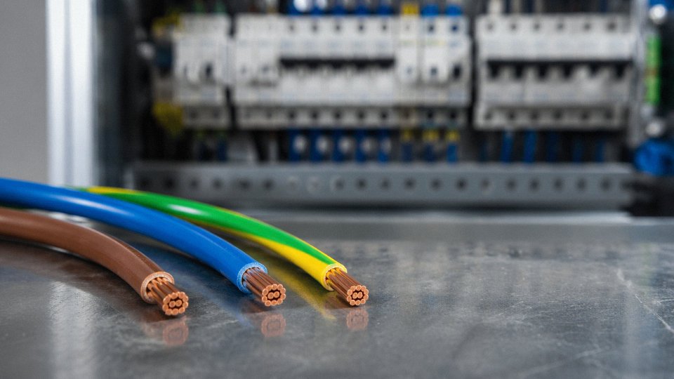
The live wire — called the hot wire in North American practice — is the conductor that actively carries voltage from the source to the load. Everything downstream of the breaker that does useful work runs on it. That single fact makes it the highest-risk conductor in any installation: touch it under load and you complete a circuit through your body, full stop.
System voltage depends on the market. North America standardizes on 120 V single-phase for residential circuits and 208/240 V for heavier loads; Europe and most of Asia run 230 V; Japan operates at 100 V, which catches overseas contractors off guard more often than it should. Industrial three-phase systems routinely operate at 400 V (Europe/Asia), 480 V (North America), or step up into the medium-voltage range entirely. In large industrial bus systems — think main switchgear feeding a steel mill or a data-center UPS backbone — prospective fault current on the live conductor can exceed 10,000 A and spike past 50,000 A in heavy utility feeds. That is not an abstraction; it is the engineering basis for every breaker interrupting rating and busbar cross-section in the plant.
In IEC 60446-compliant systems, brown identifies the single-phase live conductor, while a three-phase system assigns brown to L1, black to L2, and grey to L3.True
IEC 60446:2010 (incorporated into IEC 60445) defines these color assignments for AC conductors in low-voltage systems. Compliance is mandatory for equipment sold into EU and most Asian markets.
Color Codes by Market: A Compliance Non-Negotiable
Color code errors are not aesthetic mistakes — they are customs-rejection triggers and, on site, they get people killed. The table below summarizes what you will actually encounter across major markets.
| Market / Standard | Single-Phase Live | Three-Phase L1 / L2 / L3 | Notes |
|---|---|---|---|
| IEC 60446 (EU, most of Asia) | Brown | Brown / Black / Grey | Mandatory post-2004; old EU used red/yellow/blue |
| North America (NEC) | Black or Red | Black / Red / Blue (common) | NEC permits other colors with labeling; red typically used for 240 V leg |
| Australia/New Zealand AS/NZS 3000 | Brown (current) | Brown / Black / Grey | Red was legacy pre-2000 — old installs still exist in existing buildings |
| China GB/T 6995 | Brown (aligned to IEC) | Yellow / Green / Red (L1/L2/L3) | Chinese three-phase color differs from IEC three-phase; verify on every export job |
Procurement managers sourcing cable for projects that cross jurisdictions — a solar farm in Southeast Asia wired with European inverters and North American switchgear, for instance — need to specify color codes explicitly in purchase orders. “Standard live wire” is not a specification.
Conductor Material, Cross-Section, and Temperature Rating
For live-wire conductors below roughly 70 mm², annealed copper dominates. IEC 60228 Class 1 (solid) suits fixed wiring in conduit; Class 2 (stranded) is the practical choice anywhere the cable flexes or terminates repeatedly. Copper’s resistivity of approximately 1.68 × 10⁻⁸ Ω·m at 20°C gives it a real ampacity advantage over aluminum — roughly 40% more current per unit cross-section — which is why nobody uses aluminum in a 2.5 mm² branch circuit.
Above 70–95 mm², aluminum alloy conductors become economically competitive for feeders and service entrances, provided terminations are rated for aluminum and anti-oxidant compound is applied. Skipping the compound on aluminum terminations causes resistance creep over 2–5 years and is a slow-motion fire hazard.
Typical ampacity ranges for copper live-wire conductors at 70°C PVC / 90°C XLPE insulation, single-core in free air (values shift with installation method, ambient temperature, and grouping factor):
- 1.5 mm²: roughly 17–19 A / 21–24 A
- 2.5 mm²: roughly 23–26 A / 29–33 A
- 4 mm²: roughly 30–35 A / 38–43 A
- 6 mm²: roughly 38–44 A / 48–55 A
- 240 mm²: roughly 430–470 A / 530–580 A
These are ranges, not guarantees. Actual derating for cable tray fill, 45°C ambient in a Middle East installation, or direct burial changes the picture considerably.
Jinda’s production lines manufacture live-wire conductors to IEC 60228, BS 6360, and UL 44 / UL 83 requirements within the same facility, which matters when a project requires dual-certification cable — say, a multinational manufacturer supplying equipment to both European and North American end users. Running separate procurement streams for each standard is a cost and lead-time problem that dual-certified production eliminates. Insulation is either 70°C PVC for general wiring or 90°C XLPE where thermal headroom is needed: motor feeder cables in a hot engine room, cables routed through a boiler area, or any application where the design current runs close to the conductor’s rated capacity.
One practical note: always verify that your live-wire insulation color survives the installation environment. Certain UV-stabilized PVC compounds hold color well outdoors; standard black NEC wire pulled through a conduit and left exposed at the termination in a sunny Florida junction box will fade, which creates inspection ambiguity years later. Not a crisis, but the kind of thing that slows down a maintenance crew at 2 a.m.
Neutral Wire: Return Path Engineering, Load Balancing in Three-Phase Systems, and Why It Is Never Truly ‘Safe’ to Touch
The neutral wire gets underestimated constantly. On a balanced three-phase system running clean resistive loads, it sits near 0 V, carries minimal current, and looks — from a multimeter reading — like nothing to worry about. That reading is deceptive, and the installations that treat the neutral as a passive, low-risk conductor are the ones that produce the ugliest fault conditions.
The Return Path and What “Near Zero” Actually Means
The neutral conductor completes the circuit by returning current from the load back to the transformer’s center tap, or in three-phase distribution, to the star-point of the supply transformer. Under perfectly balanced three-phase loading, the vector sum of the three phase currents cancels at the neutral, and the conductor carries essentially zero current. Real installations are never perfectly balanced. A light commercial building might have 60–70% of its single-phase loads on one or two phases, leaving the third relatively unloaded. That imbalance shifts the neutral point voltage away from true earth potential.
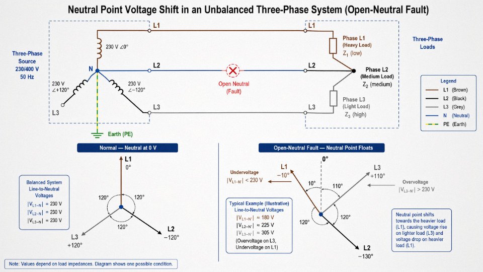
A practical example: on a 230/400 V TN-S system, a 10% load imbalance between phases — not unusual in a mixed-use building with uneven single-phase distribution — can push neutral-to-earth voltage to 15–35 V depending on source impedance and cable length. Push that imbalance higher, or introduce a high-impedance neutral connection (a loose terminal, corroded joint, undersized conductor running hot), and you can see neutral-to-earth voltages that genuinely bite. Open-neutral faults are worse. With the neutral severed upstream and unbalanced loads still connected, phase voltages redistribute across the load impedances. Lightly loaded phases see voltages well above 230 V; heavily loaded phases drop below it. Equipment burns out. It happens faster than most plant managers expect.
Under open-neutral fault conditions in an unbalanced three-phase system, phase-to-neutral voltages can redistribute significantly above and below rated voltage, causing equipment damage.True
With the neutral conductor broken, the neutral point floats. Load impedances form a voltage divider across the 400 V line-to-line voltage. Lightly loaded phases experience overvoltage; heavily loaded phases experience undervoltage. This is established electrical engineering principle and documented in IEC fault analysis literature.
Conductor Sizing: The Rules Change With the Harmonic Content
IEC 60364-5-52 is the reference most international projects work from. For copper conductors up to 16 mm², the neutral must match the phase conductor cross-section — no reduction allowed, full stop. Above 16 mm², reduction is permitted, but only when the load is balanced, harmonic content is low, and the neutral is protected against overcurrent. In practice, the conditions allowing reduction are met less often than designers assume.
Data centers, server rooms, office buildings full of switched-mode power supplies, and any facility with significant variable-speed drive loading change the picture entirely. These loads generate strong third-harmonic currents — triplen harmonics at 150 Hz, 450 Hz — and those harmonic components do not cancel at the neutral the way fundamental-frequency currents do. They add. The neutral conductor in a data center feeder can carry 150–200% of the phase conductor current even when the phases appear balanced at fundamental frequency. Specifying a neutral conductor sized identically to the phase conductor in that environment is an undersizing error. It causes neutral conductors to run hot, accelerates insulation aging, and in severe cases trips thermal protection or causes insulation failure. The fix — upsizing the neutral to 150–200% of phase cross-section — is well-established but still missed on procurement drawings more often than it should be.
Color Identification and Insulation Quality in Neutral Conductors
Color coding for neutral conductors follows regional standards: blue under IEC 60446 and adopted across most of Europe and international markets, white or grey under NEC for North American installations, and light blue per GB/T 6995 in China. The color distinction matters operationally — a misidentified neutral during maintenance is how energized conductors get handled without proper caution.
Insulation integrity on the neutral is as critical as on the phase conductor, despite the lower normal operating voltage. Jinda’s production process holds insulation wall thickness tolerances within ±5% across the extrusion run — tighter than many commodity producers manage — because wall variation directly affects dielectric performance over the cable’s service life. Every low-voltage cable leaving the line passes a spark test at 6 kV, which catches pinholes, thin spots, and contamination voids that visual inspection misses entirely. Over a rated service life exceeding 30 years, those micro-defects are where insulation failures originate, usually in the worst possible locations: buried conduit, inaccessible cable trays, connections inside switchgear.
The neutral is not a safe wire. It is a conductor that behaves safely only when everything else is working correctly.
Ground Wire (Earth Wire): Fault Current Paths, Protective Conductor Sizing per IEC 60364, and the Difference Between Grounding and Bonding
The ground wire — called the protective earth (PE) conductor in IEC terminology — does nothing during normal operation. Zero current flows through it on a healthy circuit. That dormancy is precisely what makes it dangerous to underspecify: you will never know it is wrong until the moment it has to work, and at that moment you have fractions of a second.
What the PE Conductor Actually Has to Do
Its sole function is to provide a low-impedance return path for fault current when insulation breaks down and a live conductor contacts an exposed conductive part — a motor frame, a control cabinet door, a conduit run. The fault current must flow back to the supply transformer through the PE conductor fast enough to operate the overcurrent protective device before touch voltage on that exposed surface reaches a lethal level.
IEC 60364-4-41 sets the limits clearly: 50 V AC in dry indoor conditions, reduced to 25 V AC in wet or outdoor locations. For final circuits in TN systems (the most common earthing arrangement in industrial plants worldwide), the maximum disconnection time is 0.4 seconds. That 0.4-second window is not generous. If the PE conductor is undersized, its impedance is too high, fault current is too low, the breaker or fuse responds sluggishly, and touch voltage on the faulted enclosure stays above 50 V long enough to kill someone. This is not a theoretical failure mode — it shows up in post-incident investigations with depressing regularity.
Sizing Rules: IEC 60364-5-54 Table 54.2
The table-based approach gives you a quick starting point for copper PE conductors:
| Phase conductor cross-section | Minimum PE conductor cross-section |
|---|---|
| Up to 16 mm² | Equal to the phase conductor |
| 16 mm² to 35 mm² | 16 mm² minimum |
| Above 35 mm² | Half the phase conductor cross-section |
There is also a 1.5 mm² absolute minimum when the PE conductor is not incorporated within a cable or conduit assembly and therefore cannot benefit from mechanical protection.
These table values assume standard conditions. For installations with high prospective fault currents — large industrial transformers, close proximity to a substation — you verify adequacy using the adiabatic equation: S = I√t / k, where S is the minimum cross-section in mm², I is the prospective fault current in amperes, t is the disconnection time in seconds, and k is a material constant (115 for copper PE conductors with PVC insulation, 143 for bare copper). In practice, if your prospective fault current at a distribution board is, say, 8–15 kA — a realistic range for a medium-sized industrial facility — the adiabatic check will often demand a larger PE conductor than the table suggests. Run both checks. Use the larger result.
Grounding Versus Bonding: A Distinction That Matters Operationally
These two terms get conflated constantly, and the confusion leads to real installation errors.
Protective earthing creates the fault-current return path back to the supply transformer’s neutral point. Equipotential bonding connects simultaneously accessible conductive parts — metallic water pipework, structural steelwork, HVAC ductwork, cable trays — to each other and to the PE system, preventing dangerous potential differences between surfaces a person might touch at the same time. A person touching a faulted motor frame and a grounded pipe simultaneously is exposed to the voltage difference between those two points, not to absolute earth potential. Bonding collapses that difference to near zero.
In industrial plant installations, running separate bonding conductors to every piece of structural metalwork is time-consuming and creates a tangle of conductors that maintenance crews inevitably disturb. Armored multi-core cables — where the steel wire armor or aluminum foil/braid is connected to the PE terminal at both ends — integrate the PE function within the cable assembly itself, simultaneously providing the fault-current return path and allowing the armor to serve as a bonding conductor along the cable route. This is standard practice in petrochemical and heavy manufacturing plants, and it is worth specifying explicitly in your cable procurement documents rather than leaving it to contractor interpretation.
IEC 60364-4-41 specifies a maximum disconnection time of 0.4 seconds for final circuits in TN systems to limit touch voltage exposureTrue
IEC 60364-4-41 Table 41.1 specifies 0.4 s as the maximum disconnection time for final circuits up to 32 A in TN systems, based on the 50 V AC touch voltage limit and human body impedance models in IEC 60479.
One operational warning worth stating plainly: never use the PE conductor as a current-carrying neutral, and never share a PE conductor between two circuits as a cost-saving measure. Both practices appear occasionally in older industrial installations and both are non-compliant with IEC 60364. The first introduces voltage on exposed conductive parts under normal load. The second means a fault on one circuit produces a voltage on the exposed parts of the other — exactly the failure the PE system is designed to prevent.
Wire Classification by Physical Construction: Solid, Stranded, and Flexible Conductors and When to Specify Each
The live/neutral/ground classification tells you what a wire does. Construction classification tells you what it can survive. Confuse the two axes when writing a purchase order and you will either over-specify (wasting money) or, more commonly, under-specify — which shows up as insulation cracking in a cable tray after six months, or a solid conductor work-hardening and fracturing inside a conduit that turns out to have more vibration than the drawing suggested.
IEC 60228 is the reference standard here. It defines conductor classes by the number and diameter of individual wires, not by voltage rating or insulation type.
Class 1: Solid Conductors
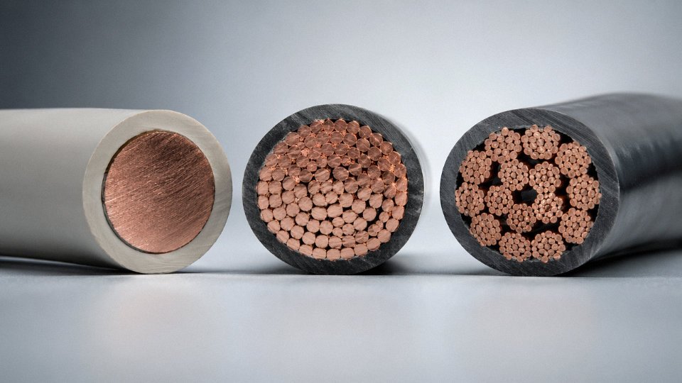
A Class 1 conductor is a single wire drawn to final diameter in one continuous operation. No stranding, no lay control — just a rod broken down through a series of dies. That simplicity makes it the lowest-cost option per unit length, and its rigid geometry gives it a predictable, stable cross-section that suits direct burial and in-conduit fixed wiring well. The conductor does not move once installed, so fatigue is a non-issue.
The limitation is exactly what you would expect. Bend a solid 6 mm² copper conductor around a tight radius more than a handful of times and it will work-harden and eventually crack at the bend. Solid conductors above roughly 16 mm² become genuinely difficult to route through conduit on-site — installers complain about this constantly, and for good reason. Below 10 mm², solid conductors are common in residential branch circuits in many markets. Above that threshold, Class 2 is almost always the better call even for fixed installations.
Class 2: Stranded Conductors
Class 2 is the workhorse of the industry. Multiple solid wires are twisted together on a stranding line with controlled lay ratios — tighter lay means better flexibility and a more compact cross-section, but also slightly higher cost due to machine time and the compaction die pass many manufacturers add. The result is a conductor that routes through conduit without the fight that solid wire gives you, tolerates the occasional repositioning during commissioning, and still delivers consistent electrical resistance across the length of a run.
Most building wire, power cables for fixed machinery, and medium-voltage distribution cables use Class 2. It balances cost and handling well enough that it is the default specification unless something about the application pushes you toward a different class.
Classes 5 and 6: Fine-Wire Flexible Conductors
These are a different animal. Class 5 conductors use a large number of fine wires — individual strands can be as small as 0.1 mm in diameter — arranged in a bunched or rope-lay configuration. Class 6 takes that further with even finer wires and tighter construction tolerances. The purpose is pure fatigue resistance. An appliance cord flexes every time someone moves it. A welding lead is dragged across a shop floor, kinked, stepped on, and coiled on a hot hook hundreds of times a week. Robotic arm cables in automated lines can exceed one million flex cycles over a service life. A Class 2 conductor will fail in these conditions. A Class 5 or 6 conductor will not — at least not from flexing.
EV charging cables are a good current example. They need to handle repeated plug-in cycles, outdoor temperatures from roughly −40 °C to +50 °C depending on region, and UV exposure, so Class 5 conductors with TPU or EPR insulation are essentially mandatory. Specifying Class 2 here is a warranty problem waiting to happen.
Practical Specification Matrix
| Application | IEC 60228 Class | Insulation Type | Notes on Bend Radius |
|---|---|---|---|
| Fixed conduit wiring (residential/commercial) | Class 1 or 2 | PVC, XLPE | Min. 4× O.D. for Class 1; installation only |
| Direct burial power cable | Class 2 | XLPE, PE sheathed | No repeated flexing; mechanical protection layer required |
| Cable tray (fixed runs) | Class 2 | XLPE, PVC | Supports needed per cable weight |
| Flexible conduit, machine connections | Class 5 | PVC, TPU | Min. 7.5× O.D.; check conduit ID for pull clearance |
| Machinery internal wiring (moving parts) | Class 5 | Silicone, PVC | Confirm temperature rating against enclosure heat |
| Portable tools and appliance cords | Class 5 | Rubber, PVC | Sheath hardness matters for operator grip and abuse resistance |
| Welding leads | Class 5 or 6 | Rubber (EPR/EPDM) | Flexibility at low temperature is critical in outdoor use |
| EV charging cables | Class 5 | TPU, EPR | UV resistance, oil resistance, cold-weather flexibility all required |
| Drag chain / robotic cables | Class 6 | TPU, special PUR | Specify minimum bend radius and cycle count with supplier |
How Construction Type Shapes the Manufacturing Process
These are not interchangeable production runs — each class requires dedicated equipment and process control. At Jinda’s production bases, solid Class 1 conductors come off single-pass wire drawing lines where rod-to-final-diameter reduction ratios and die geometry are optimized for dimensional stability. Class 2 stranded conductors move through multi-wire stranding machines where lay ratio, compaction die pressure, and wire tension are monitored to hit the IEC resistance values and ensure a consistent, round cross-section that feeds cleanly through downstream extrusion.
Fine-wire flexible conductors — Class 5 and 6 — require a different upstream process entirely. Individual wire diameters down to 0.1 mm demand ultra-fine drawing lines with tight annealing controls; if the annealing temperature drifts, the wire comes out either too brittle or too soft, and both conditions cause problems in service. After drawing, the fine wires go through bunching or rope-lay stranding equipment that is mechanically quite different from a standard stranding line. Dedicating specific production lines across five manufacturing bases to specific conductor classes is not just an efficiency choice — it is the only realistic way to maintain consistent quality across high-volume orders without constant line changeovers that introduce process drift.
IEC 60228 Class 5 conductors are required for cables subjected to repeated flex cycling exceeding one million cycles in robotic and drag-chain applicationsTrue
IEC 60228 Class 5 specifies fine-wire stranded conductors designed for flexible applications; Class 1 and 2 solid or standard-stranded conductors will fatigue and fracture under sustained repeated bending, making Class 5 or 6 the correct specification for high-cycle robotic and drag-chain cables.
The practical takeaway for procurement: always specify IEC 60228 class explicitly on your purchase order, not just cross-sectional area and voltage rating. Two 4 mm² 450/750 V cables can look identical on a basic spec sheet and behave completely differently once installed in a moving application. Getting that one field right on the datasheet saves a rework call six months later.
Wire Classification by Insulation Material: PVC, XLPE, and Rubber — Performance Thresholds, Temperature Limits, and Application Boundaries
Choosing a conductor material gets most of the attention in wire specifications, but the insulation wrapped around that conductor is what actually determines whether the cable survives the installation environment. Get it wrong and you are looking at premature cracking, dielectric breakdown, or — in confined spaces — a smoke event that shuts down an entire facility. There are three dominant insulation families worth understanding in depth: PVC, XLPE, and the rubber/elastomeric group.
PVC: The Default That Has Real Limits
Polyvinyl chloride is the global workhorse for general-purpose low-voltage wiring, and for good reason. Standard PVC insulation operates comfortably from roughly −15°C to +70°C, with heat-resistant HR-PVC grades pushing that upper limit to 90°C. Volume resistivity sits above 10¹⁴ Ω·cm, which is more than adequate for residential and commercial distribution. It resists oils and mild acids reasonably well, processes easily on extrusion lines, and costs less per kilogram than every alternative discussed here.
The problem shows up at the boundary conditions. Above 70°C, PVC softens and its mechanical properties deteriorate — a cable routed near a heat source or bundled tightly in a conduit under full load can reach that threshold faster than the design assumed. Outdoor exposure without carbon-black pigment or UV stabilizer additives causes surface chalking and eventual cracking within a few years in high-UV climates; I have seen this on roof-mounted equipment wiring in Southeast Asia installations where someone substituted standard indoor PVC for an outdoor-rated spec to save a few cents per meter.
The more serious limitation is combustion behavior. PVC releases hydrogen chloride gas and dense, toxic smoke when it burns. That single characteristic drove the shift to low-smoke zero-halogen (LSZH) cables across tunnel infrastructure, public transport systems, hospitals, and data centers — anywhere evacuation is slow or enclosed. If your project specification references IEC 60332-3 flame propagation or IEC 60754 halogen content testing, standard PVC will not pass.
XLPE: The Right Choice Once Voltage or Temperature Climbs
Cross-linked polyethylene is chemically a different material from standard PE despite the similar name. The cross-linking process — whether peroxide-initiated, silane moisture-cure, or electron-beam irradiation — creates a three-dimensional polymer network that resists thermal deformation, moisture ingress, and chemical attack in ways that thermoplastic insulations simply cannot match.
Continuous operating temperature for XLPE is 90°C, and short-circuit withstand (one-second fault) can reach 250°C without the insulation losing structural integrity. Dielectric strength typically falls in the 20–30 kV/mm range, which explains why XLPE became the dominant insulation for medium-voltage cables from 1 kV up through 36 kV, and is standard on high-voltage transmission cables above that. It contains no chlorine, so combustion toxicity is substantially lower than PVC. Moisture resistance and resistance to thermal aging mean service lives of 30–40 years are realistic in properly installed medium-voltage systems.
Jinda’s 35 kV XLPE power cable product line is built around this insulation system — that voltage class is exactly where XLPE’s superior dielectric strength and thermal stability justify the cost premium over PVC.
XLPE insulation can withstand short-circuit temperatures up to 250°C for a one-second fault duration without losing dielectric integrityTrue
This is consistent with IEC 60228 and IEC 60502 standards for XLPE-insulated cables, which specify a maximum conductor temperature of 250°C under short-circuit conditions lasting up to one second, compared to 160°C for PVC-insulated cables.
Electron-beam cross-linking, worth noting, produces a more uniform cross-link density than silane cure and is preferred for thin-wall insulation on smaller conductors — but the capital cost of an e-beam facility is significant, so silane cure dominates for medium-voltage cable production at most plants including high-volume Chinese manufacturers.
Rubber and Elastomerics: When Flexibility and Extremes Are Non-Negotiable
Standard PVC and XLPE become problematic at low temperatures — both stiffen and can crack during installation in cold environments. This is where rubber-based insulations earn their place.
EPR (ethylene propylene rubber) stays flexible from −40°C to +90°C continuous service. Its corona discharge resistance is genuinely superior to XLPE, which makes it the preferred insulation for mining cables operating in variable-voltage environments, and for shipboard wiring where mechanical flexing, vibration, and moisture are constant factors. EPR is not cheap, and it requires more careful extrusion control than PVC, but for those applications the alternatives fail sooner.
Silicone rubber sits at the extreme end of the temperature range: −60°C to +180°C continuous, and it remains pliable at cryogenic temperatures where most other insulations turn brittle. Wiring in industrial ovens, lighting fixtures with high lamp temperatures, and some aerospace applications rely on silicone for exactly this reason. The drawback is mechanical weakness — silicone tears more easily than EPR under abrasion, so a silicone-insulated conductor often needs a protective outer sheath.
Neoprene (polychloroprene, CR) is less commonly used as insulation but appears frequently as a jacket compound on outdoor portable cables. Its ozone resistance, weathering durability, and abrasion toughness are well above PVC, which is why you see neoprene-jacketed portable power cables on construction sites, agricultural equipment, and outdoor entertainment setups.
Insulation Material Comparison at a Glance
| Property | PVC | HR-PVC | XLPE | EPR | Silicone |
|---|---|---|---|---|---|
| Max continuous temp | 70°C | 90°C | 90°C | 90°C | 180°C |
| Min install temp | −15°C | −15°C | −25°C | −40°C | −60°C |
| Dielectric strength | Moderate | Moderate | High (20–30 kV/mm) | High | Moderate |
| Flexibility | Fair | Fair | Fair | Excellent | Excellent |
| Flame/smoke behavior | Poor (HCl, dense smoke) | Poor | Better (no Cl) | Good | Good |
| UV resistance | Poor without additive | Poor without additive | Good | Good | Good |
| Relative cost index | 1× | 1.1–1.3× | 1.5–2× | 2–3× | 4–6× |
| Typical applications | General LV wiring | Panel wiring, appliances | MV/HV power cables, 1–36 kV | Mining, marine, portable | Oven wiring, high-temp industrial |
Cost indices are approximate and shift with raw material prices — PE and EPR resin prices track petrochemical feedstocks more directly than PVC compounds do, so the spread between them narrows or widens with oil price cycles. Always verify current pricing before finalizing a bill of materials.
The practical takeaway for procurement: insulation material is not a detail to leave to the cable supplier’s standard offering. Temperature class, halogen content, flexibility requirement, and UV exposure are all factors that should appear explicitly in the purchase specification, not be inferred from a cable designation alone.
Three-Phase Wiring Systems: How Live, Neutral, and Ground Scale from Single-Phase Circuits to Industrial Power Distribution
Single-phase wiring — one live conductor, one neutral, one protective earth — is straightforward enough that most electricians can rough it in from memory. But virtually every industrial facility, commercial building over a certain size, and grid-connected renewable energy plant runs on three-phase power, and that’s where the same three functional wire types suddenly multiply, interact, and create specification problems if the engineer doesn’t understand the underlying logic.
From Single-Phase to Three-Phase: What Actually Changes
A single-phase circuit uses three conductors: 1L + N + PE. A standard three-phase four-wire system uses five: 3L + N + PE. The three live phases (typically labeled L1, L2, L3, or R, S, T in some European conventions) are displaced 120° apart electrically. That phase displacement is the entire reason three-phase systems dominate industry — a three-phase motor or resistive heating bank draws current from all three live phases simultaneously in a rolling, overlapping pattern. The result is roughly 73% more delivered power per unit of conductor copper compared with a single-phase circuit of the same cross-section. For a factory running dozens of motors, that difference isn’t academic; it directly determines cable sizing, transformer rating, and busbar costs.
The neutral conductor in a balanced three-phase load theoretically carries zero current, because the three phase currents cancel each other at the star point. In practice, no industrial load is perfectly balanced — you’ll always have some single-phase lighting circuits, control gear, or VFD drives introducing harmonic distortion, and the neutral ends up carrying residual unbalanced current plus triplen harmonics (3rd, 9th, 15th…). This is why upsizing the neutral to match or even exceed the phase conductor cross-section is sometimes the correct call in facilities with heavy non-linear loads, not an over-specification mistake. The single PE conductor, meanwhile, still protects all three phases from fault-to-earth events, which is one of the more elegant aspects of three-phase protective design.
IEC Grounding Configurations: TN-S, TN-C-S, and TT
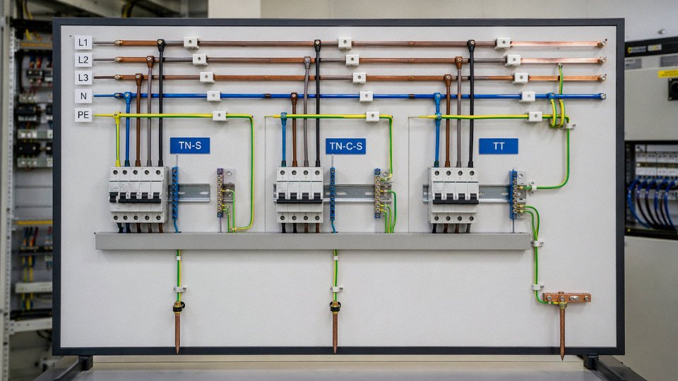
IEC 60364 defines three grounding system types that determine how N and PE are arranged between the source and the load, and getting this wrong has real consequences.
TN-S keeps the neutral and protective earth as completely separate conductors throughout the entire installation. Sensitive electronics — variable speed drives, medical imaging equipment, data centers — demand TN-S because combining N and PE anywhere in the system introduces noise on the protective conductor. It costs more copper, but the interference immunity is worth it.
TN-C-S is the configuration you’ll encounter most often in European industrial practice. A combined PEN conductor runs from the substation or transformer to the main distribution board (MDB) of the building. At the MDB, the PEN is split: N goes to the neutral bar, PE goes to the earth bar, and from that point forward they remain separate. The split point, sometimes called the earthing point or separation point, is where your grounding rod or building steel connection is made. Most factories in Germany, Poland, and across northern Europe are wired this way. The PEN conductor upstream of the MDB must be sized to carry both load-return current and fault current simultaneously, which typically means it cannot be smaller than 10 mm² copper.
TT systems use an independent earth electrode at the installation rather than relying on a metallic return path to the source. The supply neutral is earthed at the transformer, and the installation earth is a separate local electrode — a ground rod, a buried ring, whatever the site permits. TT is standard in many rural networks across France, parts of Asia, and most developing-country distribution systems where the supply infrastructure can’t guarantee a low-impedance metallic earth path. Because the fault loop impedance in a TT system tends to be high, residual current devices (RCDs) are essentially mandatory — you can’t rely on overcurrent protection alone to clear an earth fault quickly enough.
A Practical Example: 10 MW Solar Farm AC Collection
Consider a utility-scale solar installation collecting AC output from multiple inverter stations at 35 kV. The three-core XLPE armored cables running between the inverter transformer and the ring main unit carry L1, L2, L3 — three live phases — within a single cable. There is no separate neutral conductor in the 35 kV collection network because the inverter transformer is delta-connected on the primary (MV) side; the neutral is managed internally at the inverter transformer’s LV star point, where the 400 V side is solidly earthed. The cable’s steel wire armoring (SWA) or aluminum wire armoring (AWA) serves as the PE conductor for the MV circuit, providing the fault return path back to the substation earth grid.
Steel wire armored three-core XLPE cables used in MV solar collection systems can use the armor as the protective conductor (PE) under IEC 60364 and IEC 60502 provisions, provided the armor cross-section meets the minimum PE sizing requirements.True
IEC 60364-5-54 and IEC 60502-2 both permit metallic cable sheaths and armoring to serve as protective conductors where their cross-section and continuity can be verified. In MV solar collection cables, armor cross-section is routinely calculated against the prospective fault current and clearance time to confirm compliance.
At the substation end, the transformer HV neutral (if star-connected) is earthed through a neutral earthing resistor or directly to the station earth grid depending on the system earthing philosophy — a detail that drives the choice between solidly earthed, resistance-earthed, or isolated neutral MV networks, each with different cable insulation voltage ratings. Specifying the wrong insulation level here can mean operating a cable rated for earthed-neutral conditions on an isolated-neutral network, which subjects the insulation to sustained overvoltages during single-phase-to-earth faults.
For procurement managers sourcing cables for projects like this, the key takeaway is that three-phase industrial and renewable energy systems don’t just use more wire — they use wire in fundamentally different configurations where the neutral may be absent, partially shared, or managed at the transformer rather than distributed through the cable run. Understanding which grounding system applies to the specific project, and communicating that clearly to the cable manufacturer, is what separates a clean specification from an expensive re-order.
How to Read Wire Markings, Order Specifications, and Avoid the Five Most Common Procurement Errors on International Projects
Getting the three wire types right electrically means nothing if the purchase order is wrong. International cable procurement fails more often at the paperwork stage than anywhere else — and the consequences show up six months later when a container arrives and nothing meets the local inspection standard.
Decoding an IEC Cable Designation Character by Character
Take a typical designation you’ll see on European and many Asian projects: N2XY 3×240/120 mm² 0.6/1 kV.
- N — German VDE-origin prefix indicating a harmonized European cable type; no letter prefix in some IEC designations simply means copper conductor, while A (e.g., NA2XY) flags aluminum
- 2X — cross-linked polyethylene (XLPE) insulation; plain Y here would mean PVC
- Y (outer sheath) — PVC outer jacket; 2Y would be polyethylene
- 3×240 — three cores, each 240 mm² cross-section (the live conductors in a three-phase circuit)
- /120 — neutral conductor at 120 mm², reduced neutral sizing as permitted under balanced three-phase load assumptions
- 0.6/1 kV — rated 0.6 kV phase-to-earth, 1 kV phase-to-phase
Contrast that with a North American designation: THHN 4 AWG. THHN tells you thermoplastic high-heat-resistant nylon-jacketed, the conductor is copper by default unless marked AL, and 4 AWG gives you roughly 21.2 mm² — which you would never see on an IEC BOM because IEC uses 25 mm² as the nearest standard size. That gap matters for ampacity calculations. A North American engineer dropping AWG sizes into an IEC project spec, or vice versa, creates a mismatch that no site inspector will overlook.
Chinese GB standard cables use yet another system — for example ZR-YJV 3×95+1×50 mm² 0.6/1 kV — where ZR denotes flame-retardant, YJ is XLPE insulation, V is PVC sheath, and the “+1×50” distinguishes a reduced neutral from equal-section cores. When you’re sourcing from China for a project that requires IEC or BS certification, those GB designations need to map cleanly onto the project spec. They often do, but someone has to verify it explicitly.
The Five Procurement Errors That Cause Real Delays and Cost Real Money
1. Mixing AWG and IEC cross-sections. AWG 12 is 3.31 mm². IEC standard is 3.5 mm². That 5.7% difference is enough to push a circuit outside NEC ampacity tables when someone re-labels the cable for an IEC project. Typical consequence: full re-pull on affected circuits, 3–8 weeks delay depending on run length and access.
2. Confusing 0.6/1 kV and 0.6/1.2 kV ratings. Some regional standards (older British BS cables, certain Middle Eastern specs) call for 0.6/1.2 kV. A supplier quoting to the lower IEC rating is not automatically interchangeable. Mixing them on the same project creates a documentation problem that can stall commissioning sign-off entirely.
3. Ordering PVC insulation for high-ambient-temperature installations. Standard PVC is rated to 70°C conductor temperature. In a rooftop conduit run in a hot climate, or near furnace equipment, ambient plus self-heating easily exceeds that. XLPE handles 90°C continuously. Using PVC where XLPE is required accelerates insulation degradation within two to four years — you won’t see the failure coming until a fault occurs.
4. Omitting armor specification for direct-burial. Unarmored cable in direct burial without a full sand-and-tile bed is a mechanical risk, and in many markets it simply fails inspection. Steel wire armor (SWA) or steel tape armor (STA) adds modest unit cost — typically 8–15% depending on conductor size — but avoiding it to save money and then having to excavate a run is an order of magnitude more expensive.
5. Skipping LSZH sheath specification for indoor public buildings. Standard PVC sheathing releases hydrogen chloride and dense smoke when burning. LSZH (low-smoke zero-halogen) is mandatory under IEC 60332 and EN 50575 in schools, hospitals, transport hubs, and most commercial buildings in Europe and increasingly across Asia and the Middle East. Discovering this after delivery means either returning the cable or carrying a non-compliance on the project record.
AWG 12 conductor cross-section (3.31 mm²) is not equivalent to IEC 3.5 mm² standard sizing, and substituting one for the other creates ampacity non-compliance on IEC-governed projects.True
AWG 12 has a nominal cross-section of 3.31 mm² by ASTM B258, while IEC 60228 defines 3.5 mm² as the nearest standard class. The ~5.7% cross-sectional difference translates directly to a lower current-carrying capacity and fails IEC ampacity compliance checks.
How Jinda’s Technical and Manufacturing Support Addresses These Errors Directly
Factory-direct technical consultation before an order is placed catches most of the five errors above before they become purchase orders. Jinda’s engineering team reviews project specifications against the destination standard — IEC, BS, AS/NZS, or a customer-specified national code — and flags cross-section, insulation, sheath, and voltage-rating mismatches before production begins.
Dual-standard certification is available for projects that need, say, IEC 60502-1 compliance documented alongside a customer’s domestic standard. That’s common on EPC projects where the owner’s specification references one standard and the local authority having jurisdiction references another.
For medium-voltage cable orders, factory acceptance testing (FAT) covers partial discharge testing up to 36 kV, conductor resistance verification, and high-voltage withstand testing. Third-party witness testing — a surveyor present at the factory during FAT — can be arranged for projects where the end client or lender requires independent verification. In practice, lenders financing large renewable energy or infrastructure projects increasingly require this, and having the capability in-house at the production base saves the two to three weeks it would otherwise take to ship samples to an external lab.
Logistics from five production bases across China means lead times and freight routing can be optimized based on destination port and urgency. Roughly 60–70% of international orders ship from the bases nearest major eastern ports, though western project destinations sometimes route differently. The point is that the manufacturing capacity exists to support bulk procurement on realistic project timelines — not just catalog quantities.
Frequently Asked Questions About Wire Types, Specifications, and Safe Installation Practices
Can I use a ground wire as a neutral in an emergency?
No — and this is one of those shortcuts that can pass inspection visually while creating a genuinely dangerous installation. A protective earth (PE) conductor is sized and routed for fault current only: intermittent, high-magnitude, and brief. It is not designed to carry continuous load current. Running return current through a PE conductor causes resistive heating in a conductor that may be undersized for that duty, and it corrupts the ground reference for every other device on the same system. IEC 60364 prohibits combining N and PE functions except in approved TN-C configurations, and even then only on the supply side — never at socket outlets or downstream of the system’s PEN split point. In practice, if you’re on a job site and the neutral is damaged, the correct emergency is to isolate the circuit, not improvise.
What happens if live and neutral are reversed at a socket or fitting?
The appliance will often appear to work normally. That’s the trap. With live and neutral transposed, the switch in a lamp or appliance interrupts the neutral conductor rather than the live. The load is off, but the entire internal wiring of the appliance — including the lamp holder or heating element — remains at line voltage relative to earth. Anyone replacing a bulb or touching a metal component inside the fitting is at serious risk of a lethal shock. This is particularly dangerous on older appliances without double insulation. A simple non-contact voltage tester catches it in seconds; reversed polarity at the supply end of a circuit is a common installation error, especially where local wiring color conventions differ from the cable a contractor actually has in hand.
Reversed live and neutral polarity leaves appliance internals live even when the switch is off, creating a shock hazard that persists invisibly.True
When neutral is switched rather than live, the load circuit is interrupted but the full line-to-earth voltage remains present on the conductors inside the appliance, confirmed by IEC 60364-4-41 requirements for switching the live conductor in single-pole devices.
Is aluminum wire acceptable for residential use?
For main feeders and service entrance conductors, yes — aluminum is widely used and perfectly acceptable when terminated with AL-rated connectors and anti-oxidant compound applied to the stripped end. The problems arise at small cross-sections (roughly 10 mm² and below) in branch circuit wiring. Aluminum creeps under terminal clamping pressure over time, which loosens connections, and its oxide layer is resistive rather than conductive unlike copper oxide. Loose, oxidizing terminations at outlets and switches are a documented ignition risk. Most codes — including those aligned with IEC 60364 — discourage or restrict aluminum in branch circuits below 16 mm² for this reason. For bulk feeder runs of 35 mm² and above, aluminum’s cost advantage is real and the risks are manageable with correct practice.
What wire gauge do I need for a 32 A circuit?
Typically 6 mm² copper for a standard 230 V single-phase circuit clipped to a surface or in free air (IEC 60364-5-52 Installation Method B or C). If the entire run is enclosed in conduit and ambient temperature stays under 30°C, 4 mm² can be sufficient under Method B2, but you need to apply the derating factors for grouping and temperature before committing — 4 mm² in a bundle of six circuits in a warm cable tray is a different situation entirely. The conductor rating also depends on insulation type: a 70°C PVC-insulated 6 mm² copper conductor is rated around 32–41 A depending on installation method, while XLPE-insulated conductors of the same cross-section carry more. Always verify against the specific installation conditions, not a generic table lookup.
What is the difference between a wire and a cable?
A wire is a single conductor — solid or stranded — with or without insulation. A cable is an assembly of two or more insulated conductors within a common outer sheath. The distinction matters in procurement because cables carry assembly costs, jacket material specifications, and armoring options that single conductors don’t. In everyday conversation on the plant floor, people say “cable” for almost everything, which causes genuine ordering errors. A spec sheet that says “supply 2.5 mm² cable” without specifying the number of cores is incomplete.
How far can a wire run before voltage drop is a problem?
IEC 60364-5-52 and most national derivatives recommend keeping voltage drop within 3% for lighting circuits and 5% for power circuits at full load. The working formula is:
V_drop = (I × ρ × 2L) / A
where I is load current in amperes, ρ is conductor resistivity (roughly 0.0175 Ω·mm²/m for copper at 20°C), L is the one-way run length in meters, and A is cross-section in mm². For a 20 A circuit over 25 meters using 2.5 mm² copper: V_drop = (20 × 0.0175 × 50) / 2.5 = 7 V, which is about 3% of 230 V — right at the lighting circuit limit. Drop to 1.5 mm² on the same run and you’re at roughly 5.8%, which is marginal for power and non-compliant for lighting. Run length, conductor size, and load current all move together; there’s no single “safe length” without knowing the other two variables.
What does LSZH mean, and when is it required?
Low Smoke Zero Halogen. When PVC insulation burns, it releases hydrogen chloride and other halogen gases — dense, toxic, and corrosive to electronics. In enclosed public spaces, metro tunnels, offshore platforms, ships, and rolling stock, those gases impede evacuation and destroy control equipment faster than the fire itself. IEC 60332-3 and IEC 60754-1/2 govern flame propagation and halogen content testing. LSZH cables are required by specification in these environments, and increasingly specified in data centers and commercial buildings even where not strictly mandated. The material costs more than standard PVC — roughly 15–30% more depending on jacket thickness and cable construction — but it’s not negotiable in the applications where it’s required.
Can Jinda manufacture cables to a custom specification or non-standard length?
Yes. Jinda’s R&D center handles custom conductor configurations, non-standard insulation materials, special shielding arrangements, and market-specific certification requirements. Minimum order quantities for fully custom products vary by complexity — standard customizations like non-standard drum lengths or specific color sequences typically have lower MOQs than novel constructions requiring new tooling. Lead times run roughly 15–45 days depending on whether standard materials are being reconfigured or a genuinely new construction is being qualified. For procurement teams working on project-specific BOMs, Jinda’s technical support team can review specifications and advise on the most efficient way to meet requirements without over-engineering the product.
Are Jinda cables RoHS- and REACH-compliant?
All Jinda products manufactured for export markets comply with EU RoHS Directive 2011/65/EU, which restricts lead, mercury, cadmium, hexavalent chromium, and specific flame-retardant compounds, and with REACH Regulation EC 1907/2006 covering substances of very high concern. Material declarations and substance compliance documentation are available for procurement teams that need them for supply chain due diligence or EU customs clearance.
What certifications do Jinda cables carry?
CCC certification covers Jinda’s domestic Chinese market products. For international supply, the portfolio includes CE marking for EU market access, IEC conformance testing across relevant product series, CPR (Construction Products Regulation) classifications for building wire sold into the EU, and product-specific approvals including UL listing for North American specifications and Lloyd’s Register approval for marine cable applications. Specific certifications vary by product line — procurement teams sourcing for a defined project should request the certificate schedule for the exact product series, not a general company certification list.